Underwater Parallel Robot for oceanic measuring and observations-remo I: development and navigation control advances. Roque Saltaren. â. , Rafael Aracil. â .
Underwater Parallel Robot for oceanic measuring and observations-remo I: development and navigation control advances Roque Saltaren∗ , Rafael Aracil† , Pedro C´ardenas¶ , Cesar Pe˜na§ , Eugenio Yime� and Cesar Alvarez‡ ∗† DISAM-UPM.
Spain. Nacional de Colombia. DISAM-UPM. Spain. § U. Pamplona Colombia. DISAM-UPM. Spain. � Universidad Aut´ onoma del Caribe. Barranquilla. Colombia. ‡ U.Universidad del Zulia, Maracaibo, Venezuela ¶ U.
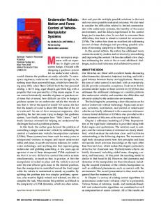
Abstract— The REMO I is a remotely teleoperated underwater vehicle developed for measuring and observing maritime environments as its mandatory task. This robot has been built based on a parallel structure (Stewart-Gough platform), with the capability of changing its geometry in order to facilitate the navigation within complex maneuvers. In addition, both orientation and propulsion systems can change in order to provide even more underwater dexterity. A thruster located in the back of its structure, which drives the vehicle forward, composes the main propulsion system of the robot. This extended abstract briefly introduces some fundamental issues related to the mechanical design, instrumentation and the control capabilities of this system.
I. I NTRODUCTION Exploring the deep sea is an exciting goal searched for ages, however such objective cannot be done safely because human beings are not capable of submerging to great depths or staying for longer periods of time. For this reason, it has always been a challenge for researchers to develop teleoperated robots that are capable of performing underwater tasks. As of today, robotics development in deep underwater exploration has advanced a lot. Despite this advances, there are still many problems not being solved optimally. Some problems are; underwater communications via ultrasound, electromagnetic severe bandwidth restrictions, low dexterity in its morphology and limited navigational capabilities. These are some of the reasons why remote control of robots is still a problem, and it is also why their capabilities of performing complex tasks in their applications are limited. As a solution to this problem, there are currently two main options for control of the underwater apparatus [1]. First is using an umbilical cable that connects the vehicle with the surface for power supply, communications and control commands. Such solution has been applied in ROV vehicles (Remotely Operated Vehicle) [2]. Control decisions are taken on land or on board by an operator. Performance of the vehicle depends on the operator skills. Second is to build an autonomous vehicle that would perform a programmed
1-4244-2523-5/09/$20.00 ©2009 IEEE
Base Universal Joints
Actuators
Thruste
Spheric Joints Fig. 1.
CAD view of REMO I, underwater parallel robot prototype.
mission and then return to its origin. These vehicles are called AUV (Autonomous Underwater Vehicle)[3], [4], [5], [6], [7]. Communication between the vehicle and the surface is usually suspended during operation. Some degree of intelligence in its main control unit has to be taken into account as some decisions in an unknown environment may be autonomously required. This paper proposes a novel application of the StewartGough platform [8] as a parallel underwater ROV, a UPR (Underwater Parallel Robot)(see Figure 1). The building of a parallel underwater vehicle presents a new challenging goal; the application of parallel robots in underwater environment requires studying the changes in its kinematics configuration in order to navigate. The Stewart-Gough (S-G) platform is a parallel mechanism with 6 degrees of freedom based on two rings that are connected by six linear actuators. These actuators are linked to the rings by spherical and universal joints. This particular kinematics configuration has well known advantages compared to serial configurations. It has also been applied in several applications [9], [10], [11], [12]. One of these important advantages is its mechanical simplicity and high rigidity, since linear actuators are actively part of its mechanical structure.
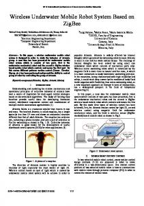
f
f r
t=r×fy
Fig. 2. Torque and force created by the thrust force when there is a relative displacement between rings.
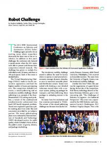
As shown in figure 1 the REMO-I’s mains parts, there are all electronics components of control In the base, sensors and power supply. The truster is fixed to the rear ring of the SG. The position and orientation of the thruster is changed with the actuators. When the S-G platforms is used to make a underwater robot, the robot has the ability the change form. An underwater vehicle with 6 d.o.f. can be done. The UPR robot can use its rings to bring only one thruster on the rear ring. In such manner, relative position and orientation of the thruster can be set up by using its six linear actuators. This setup allows using only one thruster and six small-power linear actuators, instead of six high powered thrusters. Besides, comparing it to other gimballed thruster designs [13], [14], its navigational ability becomes better as relative position between its rings can be changed. Figures 2 show this navigational ability of the vehicle. Figure 9 shows a photograph of the prototype of the last developed UPR robot. It shows the mechanical structure of the S-G platform and the two rings. The thruster can be seen at the rear ring and all the navigation hardware and sensors at the front ring. This robot has been firstly designed in order to carry load in navigation or inspection task. In such manner, the UPR S-G platform is a geometrical variable vehicle that requires less number of thrusters to navigate than other underwater vehicles like ROV’s [1], [15], [16], [3]. The rings in a UPR robot can be oriented in the three angles (roll, pitch and yaw) and be positioned by its linear actuators. Moreover, a UPR vehicle can be controlled changing position and orientation of its rings and controlling thruster velocity. Such higher manoeuvrability can be seen in Figure 3 where a submarine photograph and a draft of the configuration of the robot are shown. The robot performs fast emerging operation. This ability gives a fast response in navigation manoeuvres. Furthermore, when a UPR robot approaches its work place, it can hold in its place by using one of its rings and work as a parallel robot with 6 degrees of freedom in performing some tasks such as inspection or welding of underwater pipes, boat maintenance or marine rescues [17], [18]. The first prototype of UPR robot has been named REMO I (spanish acronym that stands for: Robot de Estructura paralela para la Medici´on Ocenanogr´afica; remo is the spanish translation of oar).
Fig. 3. REMO I emerging operation. Top: cad image of the configuration of the robot. Bottom: underwater image.
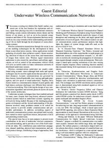
II. NAVIGATION CAPABILITIES OF A PARALLEL ROBOT This section shows several open-loop simulations made for the last prototype of a UPR robot REMO I. The simulations have been done by using software package MSIMHYD [19] developed by the authors. It uses the model presented on section III. These simulations study the hydrodynamic behavior and the navigation of underwater parallel robots. A desired displacement velocity was selected for each simulation. Drag force was calculated by using the results of the CFD simulations. These parameters stay constant during simulations. Calculated variables were rudder orientation and position. The goal was to prove high potential uses of the S-G based UPR robot. Two possible rudder-ring configurations for robot motion control are shown in Figure 4. Upper figure shows a vertical displacement of the rudder-ring in relation to the robot axis. These displacements create a torque over the robot´s body due to thruster force. Lower part of the figure shows that the relative position of the rudder-ring modifies robot behavior in rotation. Figure 5 shows the robot evolution in open loop navigation when thruster force is 300 N and velocity 1.3m/s. Three different cases are shown: • Upper part of the figure shows when robot modifies its trajectory upwards. To orient the rudder-ring (according to the frames explained in Figure 7), a path planning module was used. The final orientation was [ 0o 15o 0o ] (expressed in Euler 313 notation). When the robot arrives to a distance of 1.26m, rise motion starts. On this open loop motions, the robot stays veering until the rudder-ring axis matches the head-ring axis. • In the middle part of the figure, a loophole manoeuvre
150 mm F
100 mm
r
50 mm 0 mm
F
x
CG y
z
F 100 mm
(a) Emerging simulation r
50 mm 0 mm
F
x
CG y
Fig. 4.
z
Different relative position and orientation of the rudder ring
that consist of orienting the rudder-ring with an orientation of [ 90o -15o -90o ] (expressed in Euler 313 notation, and related to the frames explained in Figure 7). • The third manoeuvre shows a downward navigation. Path planning module was used in getting an orientation of [ 0o -20o 0o ]. According to simulations in Figure 5, navigation of a UPR robot can be done with only one thruster. This navigation is controlled by displacing and orienting the rudder-ring in relation to the reference frame of the head-ring. Figure 6 shows simulation results of five trajectories that were generated by displacing the rudder-ring with and without changing the relative orientation. 1) Changing velocity without changing its relative position and orientation. This figure shows that a circular trajectory of the UPR robot does not depend on the velocity, but on the position and orientation of the rudder-ring. Two trajectories with different velocities (V = 0.5m/s and V = 1m/s) and with the same relative orientation (20o ) for the rudder-ring were plotted. 2) Displacing the ring without changing relative orientation. This figure shows the trajectories plotted on a Surge (X)-Heave (Z) plot of three different simulations when the distance of the rings were 50, 100 and 150mm. (Figure 4 up). This figure was caused by a booster force of 300N and a velocity of 1, 2m/s. 3) This figure shows results when relative orientation of the rudder-ring is 10o and displacements are 0, 50 and 100mm. 4) This figure shows the same results when the relative rotation has been establish to 15o . 5) The same for 20o . The combination of multibody computational model with hydrodynamic model of an underwater parallel robot (robots
(b) Following a trajectory
(c) Downward navigation Fig. 5.
Navigation of the REMO robot in open loop
that are capable of undergoing complex kinematics postures), allows having powerful tools that help in obtaining more realistic results, and consequently obtain better analysis and design. See Figures 1, 4 and 5. III. H YDRODYNAMICAL MODEL A. Introduction There are few references about modelling of underwater multibody systems in specialized literature [20], [21]. One of these works is reported by McMillan in [22]. The Dynamechs software package [23] includes several libraries for modelling and simulation of multibody systems based on the formulation used in [24], [25]. In a different way, this paper explains a computational model based on Fossen equations (equation (1))
Trayectory for Displacement z = 50, 100, 150
Heave Distance - m
Heave Distance - m
Superposition for rotation 20º, V=0.5 and 1.8 m/s
z=150 z=100 z=50
Surge Distance - m
Surge Distance - m
(a) Simulation with two different velocities without changing the relative position and orientation between rings
(b) Changing the relative position
Trayectory for Displacement 10º d=0.5 and 100 mm
Trayectory for Displacement 15º d=0.5 and 100 mm d=0
Heave Distance - m
Heave Distance - m
d=0 d=50 d=100
d=50
d=100
Surge Distance - m
Surge Distance - m
(c) Changing the relative orientation to 10o
(d) Changing the relative orientation to 15o
Trayectory for Displacement 20º d=0.5 and 100 mm d=50
Heave Distance - m
d=0
d=100
Surge Distance - m
(e) Changing the relative orientation to 20o Fig. 6.
Simulated circular trajectories for the UPR robot TABLE I SNAME NOTATION
[26] that have been adapted to geometry-variable underwater vehicles. Mν˙ + C(ν)ν + g(η) = g(0) + ω + τ η˙ = J(η)ν
(1)
motion in x-direction (surge) motion in y-direction (sway)
Equations (1) have been written using SNAME notation (The Society of Naval Architects and Marine Engineers) for underwater vehicles. Table I summarizes this notation. In equations (1) M is the mass matrix (that includes the rigid body mass and the added mass, M = MRB + MA ), C(ν) is the Coriolis matrix (to account the effects of the non-centroidal reference frames of the underwater vehicle, C = CRB + CA ), D(ν) is the non-linear matrix of the damping effects, g(η) is the vector of restitution forces and torques, ω is the array of the external forces and torques due to the waves and marine streams and τ is the vector of the thruster
motion in z-direction (heave) rotation about x-direction (roll-heel) rotation about y-direction (pith-trim) rotation about z-direction (yaw)
Position and Euler angles x y z φ θ ψ
linear and angular velocities u v w p q r
forces and moments X Y Z K M N
forces and torques. Equations (1) are useful for modelling dynamics of underwater vehicles with only one hull, like boats, submarines, ROV’s, etc. It is important to include hydrodynamical effect of each of the bodies of the kinematic chain to the dynamic
effects of the rigid body when developing a model for articulated underwater vehicles that modify their geometry during navigation. B. Dynamic model of a variable geometry robot The proposed dynamic model for a UPR robot is developed by mixing multibody theory (we have used notation by Haug [27]) and equations (1) for mono-hull underwater vehicles. More detailed explanation can be found in [19]. head-ring yi
Fig. 8.
Pressure isosurface obtained with CFD software
{g}
{i}
rg,i
xi
rudder-ring
CG
Applying to a n bodies system, the definitions of added mass and viscous drag, the equations below are derived.
Thruste zi
UPR Robot
r0,i
˙ − Ca (V)V Qa = −Ma V
(6)
Qd = −D(V)V
(7)
rc, i z y Intertial frame
{0}
x
Fig. 7.
Reference frame and SNAME notation for UPR robot
The fist step is to adapt multibody equations to noncentroidal reference frame shown in Figure 7. To complete these dynamic equations, geometric and kinematics constraints had to de added between the links of the mechanism. A vector with holonomic and actuator constraints is defined. This vector (Φ(q)) groups the kinematic constraints required by the spherical joints, universal joints or the prismatic actuators. ⎤ ⎡ Φ1,2 ⎥ ⎢ (2) Φ(q) = ⎣ ... ⎦ Φn−1,n Using the Lagrange theorem the dynamic multibody equation is obtained:
where,
˙ + CRB V + Φ∗T λ = Q MRB V q
(3)
MRB = diag(MRB,1 , . . . , MRB,n ) CRB = diag(CRB,1 , . . . , CRB,n )
(4)
Equation (3) is expressed by a non-centroidal reference frame for each body. To complete the equation for underwater multibody systems, hydrodynamical stream forces, added mass, viscous drag, waves effects, external forces of gravity and thruster forces have to be included on the Q vector. This Q vector can be expressed as: Q = QB + Qa + Qd + Qw + Qg + Qr
(5)
Where Ma = diag(Ma,1 , . . . , Ma,n ) and Ma,i are the added mass matrix for body i. It has to be calculated by software [28]. Ca (V) = diag(Ca,1 (V), . . . , Ca,n (V)), where Ca,i (V) is the Coriolis matrix due to the added mass of each body. D(D) = diag(D1 (V), . . . , Dn (V)), where Di (V) is the viscous drag for i body. Using equations (5) to (7) in (3), the equation below is obtained: ˙ + C(V)V + D(V)V + Φ∗T MV q λ = Qe
(8)
M = MRB + Ma C = CRB + Ca Qe = QB + Qw + Qg + Qr
(9)
where,
C. Hydrodynamical parameters Added mass matrix Ma , Coriolis matrix Ca and Damping matrix D of equations (6) and (7) have to be derived in order to simulate the robot performance. CFD software PowerFlow [29] has been used and hydrodynamic parameters in several critical configurations have been calculated. Several velocities were applied on the simulations (0.5, 1, 1.5 and 2.0) m/s. Drag forces and added mass were obtained for each body. Parameters for an intermediate velocity were obtained by interpolation. Variation with real values will be treated as an uncertainty with a robust controller. These simulations therefore conclude that its hydrodynamic parameters could be calculated independently for each of its bodies without having significant deviations. The head-ring, rudder-ring and the six linear actuators have been calculated by this methodology. The hydrodynamic model (equation 8) was used getting the simulations in section II. The figure 6 shows simulation results of five trajectories.
IV. P ROTOTYPE REMO I ROBOT A. Structure The figure 9 show a photograph of the end prototype. A
Ballast Cavities Front
Rear
Rudder-ring
SG platform
lead-ring
Air tank
Fig. 9.
Last model of the robot - REMO I.
S-G Platform
modular-design concept and an optimization of the inner space have been considered in designing and manufacturing the head-ring (where the control is allocated) and the rudder-ring (where the truster is located). As it can be seen in Figure 10, complicated hollows had to be machined in its structural parts in order to make room for some electronics. Some important points its are: 1) Robot rings are made of high density polyethylene. Each head-ring module has 100 mm wide and has been mechanized by water jet cutting machine. Upper photograph of Figure 10 shows the head-ring assembly. 2) A cover with a hollow to allocate an IP-TV camera has been assembled in the front part of the head ring 10 3) An important part is the one shown in figure 10. This part is used to reduce the use of expensive interfaces for the electrical cables. This part can be unmounted easily and it allows to concentrate all the electrical cables of the linear actuators and the thruster. 4) The S-G platform has been built using two aluminium rings assembled with inox steel screws to the head-ring and the rudder ring. See figure 10 5) The cover thrust is made of high density polyethylene for above turbulence. Each of its six linear actuators has been built by using the carcass of a 42 diameter ISO pneumatic cylinder. The rod of the cylinder has been replaced by a steel-made ball screw SKF-12x4R that is driven by a 70 W DC motor (Maxon RE26). The thruster is made up of a 1.1 KW brushless motor (Control Techniques EPSILON EZD - 3000 rpm) and a 150 mm propeller of 350 N drag force. First tests were done by pressurizing the inner of the headring and linear actuators with a pressure of 1 bar from two
Actuator Fig. 10.
3 images of the different parts of REMO I.
diving bottles. A water resistant Pireflex H07RN F cable was used for transporting the power. Table II shows main mechatronic parameters of REMO I prototype. B. Control system The control system of the proposed underwater robot is shown in Figure 11. This scheme shows two layer control architecture: 1) On board control layer: . This layer is based on a Galil 4080 multiaxis board to control the linear actuators and the thruster in a close loop of the S-G platform. Communication of this layer to the land surface is by fiber optic ethernet (100 Base-T). Commands for orientation and position of the rudder-
TABLE II M ECHATRONICS CHARACTERISTICS Dimensions Total weight Max velocity
User Interface
1500 mm x 1200 mm x 250 mm 90 kg 2 m/sec Converter to F-O
S-G Stainless steel ball screw DC motors with encoder Rotary shaft seals for DC motors
ELECTRIC LINEAR ACTUATOR
SKF SDS/BDS 12x4 Rx600 mm stroke Maxon motor RE26, 24v, 70 watts VARILIP, Turcon Busak + Shamban
under water REMO I
Converter to F-O
T HRUSTER SYSTEM Propeller Brushless motor Rotary shaft seals for thruster motor
Vetus 150 mm/350 N thrust force Control Techniques EPSILON EZD 1.1 KW / 3000 rpm VARILIP, Turcon Busak + Shamban
Switch control Galil 4080
Camera IP
Warning Sensors
O N - BOARD HARDWARE Multiaxis motion control board Attitude reference system unit Depth sensor Flood sensor Differential pressure Electronic compass Electric underwater connectors Umbilical electric cable Signal transmission TV IP Camera
GALIL DMC 4080 8 axis MicroInfinity Marion mod MI GA3350M Keller pressure sensor DAA21 Honeywell LLE10200 Honeywell 24PCFFM1D Honeywell HMC1001 HMC1002 MacArney Subconn Pireflex H07RN
Converter to RS 232
Actuator S-G Driver Truster
IMU
Ethernet Optic Fiber Fig. 11.
S. Lastre
Control architecture of the REMO-I.
Optical fiber Grandtec Grand IP
ring in order to follow a trajectory are usually the data being transported. This layer also sends video and on-board sensor signals to the surface. Two kind of sensors have been used: • Safety sensors: interior humidity sensor, flood detector, temperature sensor, pressure sensors and depth sensor. • Navigation sensors: electronic compass and inertial unit IMU 2) Land surface control layer: . This layer is allocated the application development in LabView. The Figure 12 shows the user interface, which main feature relies on configuring the control system and to visualize the state of the system, taking into account that the information is captured from the sensors which are onboard. The tasks of this layer are: • To control navigation and safety conditions of the robot. • To show the user three user interfaces: standard navigation interface, robot calibration interface and emergency interface. • To close navigation control loop with the data of the electronic compass and inertial unit IMU. • To solve kinematics control algorithms for the S-G platform. Multibody dynamics and a virtual reality simulator that help navigation are also set up on this layer. In order to manipulate the UPR, a joystick device control is used. First of all, the whole buttons of the joystick ought to
be configured just for specific robot motion (such as rotations and translations). The points taken by the joystick could be extremely separated from each other, then; a non-desired smooth robot motion is executed. To solve this inconvenient, intermediate points are generated by the Trajectory generate module (TGM, avoiding singularities). The information provided by the TGM is sent to the onboard control card, in which the move control loops are closed. 3) Pressurization system: The pressurization system is used to maintain the internal pressure of the lead-ring above the water pressure. The pressurization system valve has two positions, it uses its control on/off valve both for injection and for the purging. 4) Ballast control: The ballast system of the robot consists of four cameras (two in the front and two in back). To facilitate the emergence of the rowing maneuver was insufflated air through its chambers. The ballast system response is different for the maneuvers of immersion and emersion. To obtain a model for the ballast system two different tests are performed. The first is to locate the UPR at a depth of 8.4 m and then fill the air chamber for a second. Using the approximation of the FOPDT the transfer function of rise is given by (10): Gout (s) =
Kout e−st 2 s (τout s + 1)
≈
−0.301e−1,5s s2 (14, 3s + 1)
(10)
In the second test, immersion, the UPR is located near the surface, then for 6 seconds empties the chambers. Using
virtual reality
user interface
Fig. 12. space Cavidad30 30
space Cavidad31 31
Being an extension of the hydrodynamic model for monohull underwater vehicles [3], [28] has also proven as another important result towards a dynamic model for an underwater multibody system. The geometry-variable system implies a new challenge for adding the hydrodynamic effects such as added mass or dragging effect in each body of the system. Recent advances in computational fluid mechanics have also led to a better calculation of these effects. Methodology in deriving these parameters and several simulation results from different configurations have also been explained. The results of a CFD computation have been interpolated in order to get a 3D evolution of the hydrodynamical parameters. The whole dynamic model has been obtained by the powerful multibody dynamic theory [27], [30], [31] and adding the hydrodynamical effects to this formulation. ACKNOWLEDGMENT The authors would like to thank the Spanish Government (Ministerio de Ciencia y Tecnolog´ıa CICYT.) under Project REMO VEM2003-20017 and Project by work has been supported and. The professor Pedro F. C´ardenas is sponsored by the Universidad Nacional de Colombia, Fundaci´on Carolina and Colciencias. The professor Cesar Pe˜na is sponsored by the Universidad de pamplona y and UPM-BCSH.
User interface of REMO I. space Cavidad 41 41
space Cavidad40 40
Front
Rear RV40
RV30 DPT30 DPT30
space 10 Cavidad 10
DPT40 DPT40 SV30
SV40
SV30
VG20
SV40
VG20
SV20 SV20
DPT51 DPT51
V10
PS10 PS10
SV10 SV10 DPT50 DPT50 DPT50
pump 10
CV20 CV20
pump 11
RV50RV50
R EFERENCES
V11
SV50 SV50 CV50 CV50
Fig. 13.
Ballast control systems of remo I.
the approximation of the FOPDT the transfer function of immersion is given by (10). Gin (s) =
−0.0102e−1,5s Kin e−st ≈ s2 (τin s + 1) s2 (15, 4s + 1)
(11)
In addition , facilitating the immersion and emersion of the robot system ballast system is fundamental for motion of the robot´s head . This control system is carried out through a PD regulator. The controller tuning was performed by the pole assignment technique. In Figure 13 shows the ballast control scheme. Figure 14 shows photos of different maneuver realized by remo-I that were generated by displacing the rudder-ring with and without changing the relative orientation. The ridder-ring was control with joystick device. V. C ONCLUSIONS The main importance of this study is to define that the SG platform not only allows a relative orientation between the two rings, but also a relative position. It thereby increases navigation capabilities of other gimballed thruster designs. One of its main results prove that UPR robots are able to navigate with only one thrusters. Other underwater robot structures require more high powered thrusters.
[1] G. Antonelli, Underwater robots: Motion and Force Control of VehicleManipulator. Spinger, 2003. [2] D. Smallwood, R. Bachmayer, and L. Whitcomb, “A new remotely operated underwater vehicle for dynamics and control research,” in Proceedings of the 11th International Symposium on Unmanned Untethered Submersible Technology, IEEE, Ed., Durham, NH, USA, 2000, pp. 370– 377. [3] C. Silpa-Anan, “Autonomous underwater robot: Vision and control,” Ph.D. dissertation, The Australian National University, 2001. [4] K. Valavanis, D. Gracanin, M. Matijasevic, R. Kolluru, and G. Demetriou, “Control architectures for autonomous underwater vehicles,” Control Systems Magazine, vol. 17, pp. 48–64, Dec 1997. [5] D. Wettergreen, C. Gaskett, and A. Zelinsky, “Development of a visually-guided autonomous underwater vehicle,” in Proceedings of OCEANS’98, IEEE, Ed., September 1998. [6] C. Silpa-Anan and A. Zelinsky, “Kambara: past, present and future,” in Proc. Australian Conference on robotics and automation. Sidney, November, 2001. [7] R. Wernli, “Auv’s the maturity of the technology,” in Space and Naval Warfare Center. San Diego. USA, 1999. [8] D. Stewart, “A platform with 6 degrees of freedom,” in Proc. of the Institution of Mechanical Engineers, vol. 180 (Part 1,15), 1965, pp. 371– 386. [9] J. P. Merlet, Les robots parall`eles. Hermes, 1997. [10] R. Aracil, R. Saltar´en, J. M. Sabater, and O. Reinoso, “Robots paralelos: m´aquinas con pasado para una rob´otica de futuro,” RIAI. Revista Iberoamericana de Autom´atica e Inform´atica Industrial, vol. 3 (1), pp. 16–28, 2006. [11] K. Liu, G. Lebret, J. Lowe, and F. Lewis, “Control of a stewart platform based robotic milling cell,” in Proc. of ASME Winter Annual meeting, Symp. on Manufacturing and control issues in a telerobotics assembly workcell, vol. 1, 1992, pp. 8–13. [12] J. M. Sabater, R. Saltar´en, and R. Aracil, “Design, modelling and implementation of a 6 urs parallel haptic device,” Robotics and Autonomous System, vol. 47, no. 1, pp. 1–10, 2004. [13] E. Cavallo, “Parallel robotic system design for the steering and guidance mechanism of an autonomous underwater vehicle,” Ph.D. dissertation, Universita degli studi di Genova, 2003.
Fig. 14.
Different maneuver trajectories for the UPR robot
[14] E. Cavallo and R. Michelini, “A robotic equipment for the guidance of a vectored thrustor auv,” in Proc. of 35th International Symposium on Robotics ISR2004, vol. 1, March, 2004, pp. 1–6. [15] J. Yuh, “Modelling and control of underwater robotics vehicles,” IEEE Transactions on Systems, Man and Cybernetics, vol. 2 (6), 1990. [16] I. Shj¨olberg, “Modeling and control of underwater robotic systems,” Ph.D. dissertation, Norwegian University of Science and Technology, 1996. [17] R. J. Saltaren, R. Aracil, and O. Reinoso, “Climbing parallel robot: A computational and experimental study of its performance around structural nodes,” IEEE Trans. on Robotics, vol. 21 (6), pp. 1056–1066, 2005. [18] J. M. Sabater, R. Saltar´en, , E. Yime, R. Aracil, and J. M. Azorin, “Teleoperated parallel climbing robot in nuclear instalations,” Industrial Robot. An international journal, vol. 33, no. 5, pp. 381–386, September 2006. [19] E. Yime, “Dynamics model for underwater parallel robots,” Universidad Polit´ecnica de Madrid , ETSII/DISAM, Tech. Rep., june 2005. [20] D. A. Smallwood and L. L. Whitcomb, “Model based dynamic positioning of underwater robotic vehicles: Theory and experiment,” IEEE Journal of Oceanic Engineering, vol. 29(1), pp. 169–186, 2004. [21] T. W. McLain, “Modeling of underwater manipulator hydrodynamics with application to the coordinated control of an arm/vehicle system,” Ph.D. dissertation, Stanford University, August 1995. [22] S. McMillan, D. E. Orin, and R. B. McGhee, “Effcient dynamic simulation of an underwatervehicle with a robotic manipulator,” IEEE Transactions on Systems, Man and Cybernetics, vol. 2 (8), 1995. [23] S.McMillan, D.E.Orin, and R.B.McGhee, Underwater Robotic Vehicles. DynaMechs: An Object Oriented Software Package for Efficient Dynamic simulation of Underwater Robotic Vehicles. TSI press, 1995. [24] S. Oh and D. Orin, “Dynamic computer simulation of multiple closed chain robotic mechanisms,” in IEEE Int. Conf. on Robotics and Automation, (San Francisco, CA), 1996, pp. 15–20. [25] O. Khatib, “A unified approach for motion and force control of robot manipulators: The operational space formulation,” IEEE Transactions on Robotics and Automation, vol. 3, pp. 43–53, 1987. [26] T. I. Fossen, Guidance and Control of Ocean Vehicles. John Wiley and Sons, 1994. [27] E. J. Haug, Computer aided kinematics and dynamics of mechanical systems. Allyn and Bacon, 1989. [28] T. I. Fossen, Marine Control Systems. Guidance, Navigation, and Control of Ships, Rigs and Underwater Vehicles. Marine Cybernetics, 2002. [29] Powerflow, “Web page software package,” http://www.exa.com.
[30] P. E. Nikravesh, Computer aided analysis of mechanical systems. Prentice Hall, 1988. [31] A. A. Shabana, Dynamics of Multybody systems, second edition. Cambridge University Press, 1999.