2009 American Control Conference Hyatt Regency Riverfront, St. Louis, MO, USA June 10-12, 2009
FrC01.4
Underwater Target Following with a Vision-based Autonomous Robotic Fish Yonghui Hu, Wei Zhao, Long Wang, and Yingmin Jia Abstract— This paper is concerned with vision-based target following control of an autonomous, ostraciiform swimming robotic fish. Based on the successful development and effective swimming locomotion control of the robotic fish prototype, we further investigate the utility of the onboard digital camera in target following task, the output of which can be processed with the embedded processor. To treat the degradation of underwater images, a modified continuously adaptive mean shift (Camshift) algorithm is employed to keep visual lock on the moving target. A fuzzy logic controller is designed for motion regulation of a hybrid swimming pattern, which employs synchronized pectoral fins for thrust generation and tail fin for steering. A simple target following task is designed via an autonomous robotic fish swimming after a manually controlled robotic fish with fixed distance. Experimental results verify the effectiveness of the proposed methods.
I. INTRODUCTION In recent years, a great variety of innovative robots have been developed through biomimetics, which attempts to create artificial systems that emulate the performance of animals [1]. Since the process of evolution has produced highly effective and power efficient biological mechanisms, copying nature will be a shortcut to technology innovation. Biologically inspired robots, as a product of incorporation of biology science and robotic technology, not only build a new paradigm for creative robot design but also serve as a tool for investigation of biological principles. In the aquatic realm, propulsion and maneuvering mechanisms used by fish are being implemented on autonomous underwater vehicles (AUVs). Compared with conventional AUV technology that employs screw type propellers for thrust generation and multiple control surfaces for maneuvering, fish achieve far superior swimming performances through coordinated control of the body and fins. The benefits that can be obtained through technology transference from fish to nautical engineering include high efficiency, great agility, station-keeping ability and reduced detection. Fish-like robots can play an important role in various underwater tasks, especially those that require operations in cluttered environments and in unsteady flow. Most studies of robotic fish focused on the hydrodynamic modelling and experimental investigation of swimming fish, This work was supported by National Natural Science Foundation of China (10372002, 060505015), National 863 Program (2006AA04Z258), NSFC (60674050 and 60528007), National 973 Program (2002CB312200), and 11-5 project (A2120061303). Yonghui Hu, Wei Zhao and Long Wang are with Intelligent Control Laboratory, Center for Systems and Control, Department of Mechanics and Space Technologies, College of Engineering, Peking University, Beijing 100871, P. R. China (e-mail:
[email protected]) Yingmin Jia is with the Seventh Research Division, Beihang University, Beijing 100083, P. R. China
978-1-4244-4524-0/09/$25.00 ©2009 AACC
as well as construction and control of artificial devices. Early research work on building hydrodynamic models uses steady-state flow theory to calculate the fluid forces on fish body, while later more realistic models, such as the twodimensional waving plate theory developed by Wu [2] and the elongated body theory of Lighthill [3], deals with inertial effects of the inviscid fluid. Among various fish-like robots, RoboTuna developed by Triantafyllou [4] in 1994 is the first and best-known artificial fish-like system. Experiments performed on RoboTuna showed that considerable drag reduction can be achieved by actively flexing the body and the tail. Subsequent engineering research produced a number of robotic fish prototypes, e.g., the mission-scale, autonomous underwater vehicle VCUUV by Anderson and Kerrebrock [5], the pectoral fin driven robotic fish “BlackBass” by Kato [6], the behavior-based robotic fish by Liu et al. [7], the undulating fin mechanism by Low [8], the various robotic fish with different design purposed by Hirata [9], and the modular robotic fish with multiple proplusors by the authors [10]. With regard to swimming control of robotic fish, greatly simplified, low fidelity hydrodynamic models [11] and kinematic models of fish body during swimming [12] are mostly employed, because the mechanisms of flow body interaction are so complex that analytical methods based on high-fidelity hydrodynamic models are computationally prohibitive for real time control. Previous research has seldom dealt with autonomous operation of robotic fish. In this paper, we present a visionbased, autonomous robotic fish in the context of underwater target following. To realize autonomous swimming, a CMOS camera is installed on the robotic fish and the huge volume of underwater visual information can be processed with the embedded processor. To the best of our knowledge, no vision-based autonomous robotic fish have been realized before and only robotic fish with simpler sensor like pressure sensor, infrared sensor have been designed [7]. In the implementation of the underwater task, a continuously adaptive mean shift (Camshift) algorithm is modified to keep visual lock on the moving target, while a fuzzy logic controller is designed for motion regulation of a hybrid swimming pattern that employs synchronized pectoral fins for thrust generation and tail fin for steering. The rest of this paper is structured as follows. Section II briefly introduces the mechatronic design and motion control of the robotic fish prototype. The algorithms for underwater target following are addressed in Section III. Experiments with the robotic fish are conducted in Section IV. Finally, we conclude the paper in Section V.
5265
Fig. 1.
Fig. 2.
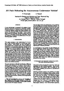
Mechanical configurations of robotic fish.
II. AUTONOMOUS ROBOTIC FISH PROTOTYPE A. Mechatronic Design Although carangiform swimming has been mostly emulated for its high speed and efficiency, our robotic fish employs ostraciiform swimming for high level of dynamic stability and excellent maneuverability [13]. Modelled after boxfish that is characterized by inflexible body and utilizes MPF mode for propulsion and caudal oscillations as auxiliary locomotion means, the robotic fish consists of a rigid main body, a pair of pectoral fins and a caudal fin. The main body, which is a streamlined, waterproofed hull made from fiberglass, provides housings for the power, electronics and actuators. The tail fin and each of the pectoral fins are actuated by Hitec HS-5955TG servomotors. The bottom cover, which functions as a chassis is screwed to the main body with O-rings between them. The reciprocatory movements of the servomotors are transmitted to the outside through dynamic sealing structure filled with grease. The rotatory range of the tail fin is limited to ±90◦ , while that of the pectoral fins is expanded to ±180◦ through transmission of gear sets of 2 : 1 ratio. A pinhole CMOS camera, as the only exteroceptive sensor is installed at the mouth position with a transparent window glued to the hull for waterproof purpose. Fig. 1 shows mechanical configurations of the robotic fish. The robotic fish is designed for autonomous operation such that it is equipped with onboard power, embedded processor, image sensor (OV7620 from OmniVision) and a duplex wireless communication module (GW100B from Unitel Pty Ltd) for interface with outside. Four rechargeable Ni-Cd cells of 2700 mAh capacity provide the robotic fish about one hour power autonomy. The control unit is a microcontroller S3C2440 that incorporates a high-performance 32-bit RISC, ARM920T CPU core running at 400 MHz and a wide range of peripherals from Samsung Electronics. The onboard memory includes 64MB SDRAM used during program execution and 64MB Nand Flash for permanent data and code storage. The microcontroller captures image data in YCbCr 4:2:2 format at 320 × 240 resolution and does realtime image processing for perception of the environment. Three PWM signals are generated by the microcontroller to control the motion of the joints. Fig. 2 illustrates hardware architecture of the control system.
Hardware architecture of the control system.
B. Swimming Locomotion Control An explicit joint angle control method is utilized for swimming control of the robotic fish. The angular value of each rotating joint is described by the following equation: θ(t) = φ + Asin(2πf t + ϕ)
(1)
where θ(t) is the angular position at time t, φ denotes the angular offset, A represents the oscillatory amplitude, f indicates the frequency and ϕ is the phase difference between joints. The swimming speed can be adjusted by modulating the frequency f and the amplitude A. The angular offset φ can be used as a strategy for maneuvering and threedimensional swimming of the robotic fish, and ϕ couples the joints for swimming pattern design. In the following, suffix t will be used to represent the corresponding parameters of tail fin, p the common parameters of pectoral fins, and lp and rp the parameters of left and right pectoral fin, respectively. Based upon the propulsive structures employed for locomotion, the swimming of fish can be classified into two categories: body and/or caudal fin (BCF) swimming and median and/or paired fin (MPF) swimming [14]. Since both the tail fin and the pectoral fins of the robotic fish can generate propulsion and maneuvering forces, swimming locomotion are be realized in both BCF mode and MPF mode. More complex movements that involves the coordinated control of the propulsors can also been realized. Typical swimming patterns that have been designed and implemented on the robotic fish are described as follows: (1) BCF forward swimming: by actuating the tail fin, with the pectoral fins held parallel to the horizontal plane. (2) BCF turning: by superimposing offsets on the oscillation of the tail joints while other parameters remain the same as the BCF forward swimming. (3) MPF forward and backward swimming: by synchronized movements of pectoral fins, with caudal fin held straight. The angular offset φp determines the swimming direction. (4) MPF turning: with pectoral fin on one side flapping forward and that on the other side backward. (5) Submerging and ascending: by adjusting the attack angle of the pectoral fins. (6) Braking: through sudden rotation of the pectoral fins to a position perpendicular to the body.
5266
III. UNDERWATER VISION-BASED TARGET FOLLOWING A. Problem Statement Vision sensors can provide high resolution information at short range and thus have been extensively used in underwater applications. However, the underwater image is plagued by several factors including poor visibility, ambient light, and frequency-dependent scattering and absorption, which make it difficult to directly employ most computer vision methods developed in terrestrial environment. In this research, since the working environment of the robotic fish is indoor shallow water swimming pool, we improve the performance of image processing by providing good lighting conditions as well as employing adaptive and robust computer vision techniques. Besides the low quality of underwater imaging, the complexity of the aquatic environment and peculiarities of the propulsion mode of robotic fish pose several additional difficulties to the successful fulfillment of underwater tasks, which are listed below: •
•
•
Unlike ground wheeled vehicles instrumented with optical encoders for speed feedback of wheel rotation, the swimming velocity and orientation of the robotic fish can not be precisely controlled and the relationship between the motor driving force and the swimming kinematics of the robotic fish cannot be accurately modelled. The robotic fish can not stop immediately due to the effect of inertial drift, and even with the swimming pattern of braking and backward swimming to counteract the forward drift the robotic fish will still overshoot slightly. Waves occur when the robotic fish flaps to swim, which can be viewed as noise added to the motion of robotic fish. The motion of the robotic fish and the target will be mutually affected through the coupling of waves, which further complicates the problem.
In this research, the robotic fish is required to follow and keep a constant distance to a moving target based on visual feedback from the monocular camera. Two distinct algorithms have been employed to perform this task. The visual tracking algorithm keeps visual lock on the moving target. The location of the target in image space and the distance between the robot fish and target are obtained in this process. Based on the output of the visual tracking algorithm, the target following algorithm generates motor control commands to keep the target stationary in the center of image and to maintain the distance to the target constant.
deformation. Mean shift algorithm is a non-parametric technique that climbs the gradient of a probability distribution to find the nearest dominant mode. As an adaptation of standard mean shift algorithm, Camshift algorithm have been extensively used in practice for head and face tracking [15]. Since the Camshift algorithm can deal with dynamically changing color probability distributions, i.e. distributions are recomputed for each frame, it fits fairly well this target tracking task where the underwater visibility degradation effect is distance dependent and spatially varying. A search window that surrounds the target is employed in Camshift for calculation of scale and location of the target. Since the change in target scale is usually caused by the distance change between the camera and the target, an innovative idea is to actively steer the mobile imaging platform to keep constant target scale in the image, so that the distance between the robot and target can be maintained. The Camshift algorithm operates on a probability distribution image that is derived from the histogram of the object to be tracked. The H channel in HSV (Hue Saturation Value) color space is mostly used for calculation of stochastic color model due to its robustness to varying lighting conditions. However, to save the computational resources spent on the conversion between color spaces, we modify the standard Camshift algorithm to let it employ Cr and Cb components of the incoming frames to calculate 2D color histogram. The Y component is discarded due to its wild fluctuation in the underwater environment. The principle steps of the Camshift algorithm implemented in this research are stated as follows: 1) Choose the initial location of the mean shift search window. 2) Calculate the 2D color histogram within the search window. 3) Perform back-projection of the histogram to a region of interest (ROI) centered at the search window but slightly larger the mean shift window size. 4) Iterate Mean Shift algorithm to find the centroid of the probability image and store the zeroth moment and centroid location. The mean location within the search window of the discrete probability image is found using moments. Given that I(x, y) is the intensity of the discrete probability image at (x, y) within the search window, the zeroth moment is computed as: XX M00 = I(x, y) (2) x
The first moment for x and y is: XX M10 = xI(x, y) x
B. Visual Tracking Visual tracking have been extensively studied in the context of computer vision to find the targets between consecutive frames in image sequences. Numerous algorithms have been proposed and implemented to track moving targets against complex and cluttered background, among which mean shift algorithm have gained considerable attention due to its computational efficiency and robustness to non-rigid
5267
y
M01 =
XX x
(3)
y
yI(x, y)
(4)
y
Then the mean search window location can be found as: M10 (5) xc = M00 M01 yc = (6) M00
5) For the next video frame, center the search window at the mean location stored in Step 4 and set the window’s size to a function of the zeroth moment. Go to Step 2. The scale of the target is determined by finding an equivalent rectangle that has the same moments as those measured from the probability distribution image. Define the second moments as: XX M20 = x2 I(x, y) (7) x
M02 =
y 2 I(x, y)
(8)
XX
xyI(x, y)
(9)
x
M11 =
y
XX x
y
y
Fig. 3.
Use the following intermediate variables: a= b = 2( c=
M20 − x2c M00
(10)
M11 − xc yc ) M00
(11)
M02 − yc2 M00
(12)
Then the dimension of the search window can be computed as: s p (a + c) − b2 + (a − c)2 (13) h= 2 s p (a + c) + b2 + (a − c)2 w= (14) 2 The mean location and size of the search window is used as output of the visual tracking algorithm. The Camshift algorithm is computationally efficient and can produce real time response to the appearance change of the target. In this research, the motion of the target is restricted in the horizontal plane, so that only xc of the search window varies as the target moves. For target that have elongated shape, the scale cannot be reflected exactly by the width of the search window when the target turns, therefore we use height of the search window as the distance clue. C. Target Following Because flapping movements at the tail will produce lateral forces that cause oscillations at the anterior part of the robotic fish where the camera locates, we employ a hybrid swimming pattern for target following. This swimming pattern which has been experimentally validated to produce minimum oscillations at the head, uses synchronized pectoral fins for thrust generation and tail fin as a rudder. The deflection direction of the tail fin produces different rotational effects during forward and backward swimming. For example, the robotic fish turns left with left deflection of the tail fin in forward swimming, while right turning will be effected in backward swimming. As a result, control of the orientation should take into consideration the direction of the translational speed. In
Membership functions of input variables.
addition, the translational speed and rotational speed of the robotic fish are coupled together. The complexity of the underwater environment and the particularity of the bio-inspired propulsion mode make it difficult to implement classical model-based control method for this task, hence we regulate the motion of the robotic fish with fuzzy logic control method, which allows management of heuristic rule base knowledge, imprecise information from sensors, and the uncertainties in the knowledge about the environment. The inputs of the fuzzy logic controller are horizontal location error ex and height error eh of the search window, which are both measured in terms of pixels and defined as: ex = xr − xc ;
e h = hr − h
(15)
where xr is the horizontal coordinate of the image center and hr is the height of search window at system startup. The value of the input variable ex is fuzzified and expressed by the linguist fuzzy sets {VL, L, A, R, VR}, referring to very left, left, ahead, right, very right, respectively. The height error eh is represented by {VC, C, M, F, VF}, abbreviated from very close, close, medium, far, very far, respectively. The initial height of the target window is 60, so that the range of eh is −180 and 60. The membership functions of the input variables are illustrated in Fig. 3. The robotic fish regulates its translational and rotational speed to follow the target. To simplify the problem, the amplitudes of the pectoral fins are held constant and only the oscillatory frequency fp is used for translational speed control, whereas the angular offset φp is used for forward and backward direction control. Backward swimming is necessary because the target may suddenly stop or reverse direction and the robotic fish have to swim backwardly to keep distance. The angular offset φt of the tail fin functions as a method for orientation control. The output variable fp of the fuzzy logic controller is expressed by the fuzzy sets {Q, S, ST}, denoting quick, slow, stop, respectively. The driving capacity of the motors determines the range of fp between 0 and 4Hz. In practical implementation, the angular offset φp of the pectoral fins is 0◦ for forward swimming
5268
TABLE I RULEBASE FOR TARGET- FOLLOWING FUZZY CONTROLLER fp , φp , φt
eh
Fig. 4.
VC C M F VF
VL Q, B, RB S, B, RB ST, F, LB S, F, LB Q, F, LB
L Q, B, RS S, B, RS ST, F, LS S, F, LS Q, F, LS
ex A Q, B, MD S, B, MD ST, F, MD S, F, MD Q, F, MD
R Q, B, LS S, B, LS ST, F, RS S, F, RS Q, F, RS
VR Q, B, LB S, B, LB ST, F, RB S, F, RB Q, F, RB
Membership functions of output variables.
(a) Translational speed in forward swimming.
Fig. 5.
Closed-loop control system of target following.
and 180◦ for backward swimming. We represent φp with two singleton fuzzy sets F and B, denoting forward and backward respectively. The output variable φt is expressed by {LB, LS, MD, RS, RB}, denoting left big, left small, middle, right small, right big, respectively. The range of the deflection is between −60◦ and 60◦ . The membership functions of the output variables, which are empirically derived based on extensive experiments with the robotic fish, are shown in Fig. 4. The architecture of the closed-loop control system is illustrated in Fig. 5. The mapping from input variables to output variables is based on the fuzzy rulebase which comprises 25 if-then rules listed in Table I. We adopt Mamdani fuzzy inference method, and the final value of the output variables are determined using the center-of-gravity (COG) defuzzification method as: P25 k k=1 µk fp (16) fp = P 25 k=1 µk P25 k k=1 µk φp φp = P (17) 25 k=1 µk P25 k k=1 µk φt φt = P (18) 25 k=1 µk
where µk is the degree of the if part of the kth rule, fpk , φkp and φkt are the estimated outputs derived from the kth rule, related to the center of the membership functions of the output variables.
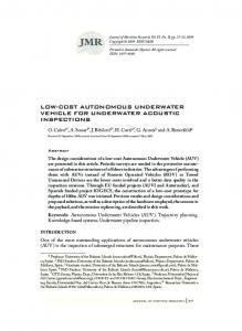
(b) Rotational speed in forward swimming. Fig. 6. Translational and rotational speeds with different frequencies fp of both pectoral fins and angular offsets φt added to the tail joint.
IV. EXPERIMENTAL RESULTS Experiments with the robotic fish were carried out in an indoor swimming tank with the size of 2250 mm × 1250 mm and with still water of 350 mm in depth. For post-analysis of the experimental result, the robotic fish is marked with specified colors and the information within the swimming tank is captured by an overhead CCD camera. The image is transmitted to a personal computer and the two dimensional trajectory of the robotic fish can be extracted and recorded. To provide solid foundation for construction of the fuzzy rulebase, the swimming performance of the hybrid swimming pattern used in target following task is tested. The translational and rotational speeds in forward swimming under different frequencies fp of pectoral fins and angular offset φt added to the tail joint are shown in Fig. 6. The moving target in the target following experiment is chosen to be another robotic fish which is remotely controlled. The performance of the Camshift algorithm is evaluated on a S3C2440 evaluation board which has LCD interface for image display. The camera is waterproofed and placed in the water, and the robotic fish is commanded to
5269
(a) Frame 4
(b) Frame 32
(c) Frame 63
(d) Frame 89
(e) Frame 107
(g) Frame 164
Fig. 8. Scenario of target following experiment. The trajectories are recorded with the overhead camera and several time points along the trajectories have been labelled to illustrate the relative position of the leader and the follower.
leader as the leader swims with varying speed and in different directions.
(f) Frame 135
(h) Frame 189
Fig. 7. Tracking results of the swimming sequence with Camshift algorithm.
V. CONCLUSIONS This paper concentrated on the underwater target following of a vision-based autonomous robotic fish. Considering the low quality of the underwater images and the peculiarities of the fish-like swimming motion, a modified Camshift algorithm and fuzzy logic control were adopted to achieve this task. The effectiveness of the proposed methods was validated with underwater experiments. R EFERENCES
swim in a circle in the swimming pool. The tracking results with stationary camera are shown in Fig. 7. As illustrated in the figure, the algorithm can reliably and accurately tracks the location of the robotic fish, and the distance change can also be reflected by the size variation of the search window. The image sequence is processed at a framerate of 25 Hz, occupying approximately 40% of the CPU time. To facilitate the description, we denote the robotic fish being followed as the leader and the tracking robotic fish as the follower. Both the leader and follower are marked with specified colors, so that the target following results can be captured with the overhead camera and analyzed with the host PC. The initial search window of the follower is located roughly in the center of the image and its initial size is 100×60. At the startup of the following process, the leader is placed in front of the follower and the distance is tuned so that the leader will fit the search window. Control period of the closed-loop control system can not be so fast as the visual processing rate due to slow response of the robot dynamics. Motor control command is generated every 200 ms based on the measurements of five frames. The data fed into the fuzzy controller M is computed with a weighted mean filter: M = 0.3Mn +0.25Mn−1+0.2Mn−2+0.15Mn−3+0.1Mn−4 (19) where Mi , i = n, n − 1, ..., n − 4 are the measurements of five consecutive frames within a control interval. Fig. 8 shows a scenario of target following experiment and the trajectories of the leader and follower. The time points along the trajectories illustrate that the follower can detect the position and distance changes of the leader and follow the
[1] F. E. Fish, “Limits of nature and advances of technology: What does biomimetics have to offer to aquatic robots?” Applied Bionics and Biomechanics 3(1), 49-60 (2006). [2] T. Y. Wu, “Swimming of a waving plate,” J. Fluid Mech. 10(3), 321344 (1961). [3] M. J. Lighthill, “Note on the swimming of slender fish,” J. Fluid Mech. 9(5), 305-317 (1960). [4] M. S. Triantafyllou and G. S. Triantafyllou, “An efficient swimming machine,” Sci. Amer. 272(3), 64-70 (1995). [5] J. M. Anderson and P. A. Kerrebrock, “The vorticity control unmanned undersea vehicle (VCUUV)-An autonomous vehicle employing fish swimming propulsion and maneuvering,” Proc. 10th Int. Symp. Unmanned Untethered Submersible Technology, 189-195 (1997). [6] N. Kato, “Control performance in the horizontal plane of a fish robot with mechanical fins,” IEEE J. Oceanic Eng. 25(1), 121-129 (2000). [7] J. Liu, H. Hu, and D. Gu, “A hybrid control architecture for autonomous robotic fish,” Proc. Int. Conf. Intelligent Robots and Systems, 312-317 (2006). [8] K. H. Low, “Locomotion consideration and implementation of robotic fish with modular undulating fins: analysis and experimental study,” Proc. Int. Conf. Intelligent Robots and Systems, 2424-2429 (2006). [9] Hirata T. Welcome to fish robot home page. 2000, Available at: http://www.nmri.go.jp/eng/khirata/fish/. [10] Y. Hu, L. Wang, W. Zhao, Q. Wang, and L. Zhang, “Modular Design and Motion Control of Reconfigurable Robotic Fish,” Proc. Int. Conf. Decision and Control, 5156-5161 (2007). [11] K. A. Morgansen, B. I. Triplett, D. J. Klein, “Geometric methods for modeling and control of free-swimming fin-actuated underwater vehicles,” IEEE Trans. on Robot. 23(6), 1184-1199 (2007). [12] J. Yu, L. Wang and M. Tan, “Geometric Optimization of Relative Link Lengths for Biomimetic Robotic Fish,” IEEE Trans. Robot. 23(2), 382386 (2007). [13] M. Gordon, J. Hove, P. Webb, and D. Weihs, “Boxfishes as unusually well-controlled autonomous underwater vehicles,” Physiol. Biochem. Zool. 74(6), 663-671 (2000). [14] M. Sfakiotakis, D. M. Lane, and J. Bruce C. Davies, “Review of fish swimming modes for aquatic locomotion,” IEEE J. Oceanic Eng. 24(2), 237-252 (1999). [15] G. R. Bradski, “Computer video face tracking for use in a perceptual user interface,” Intel Technology Journal, 2nd Quarter (1998).
5270