high accuracy in regions of smooth ow, together with some positivity property that ... In this paper we show a strong relationship between the two types of schemes. ... law. 3 documents several schemes of the control volume type, and shows how ... We are interested here in the steady-state solutions (2.1), i.e. the case when.
Series Logo Volume 00, Number 00, Xxxx 19xx
UNIFICATION OF SOME ADVECTION SCHEMES IN TWO DIMENSIONS D. SIDILKOVER AND P. L. ROE
Submitted to Math. Comp.
The rst author was supported by DOE grant DE-FG02-92ER25139, while he was in residence at Courant Institute of Mathematical Sciences, 251 Mercer st., New York University, New York, NY 10012. Both authors were also supported in part by the National Aeronautics and Space Administration under NASA Contract No. NAS1-19480 while in residence at the Institute for Computer Applications in Science and Engineering, (ICASE), NASA Langley Research Center, Hampton, VA 23681. c 0000 American Mathematical Society
i
0000-0000/00 $1.00 + $.25 per page
1. Introduction The perfect scheme for numerical advection still awaits discovery. Its attributes should include high accuracy in regions of smooth ow, together with some positivity property that avoids overand undershoots near discontinuities. It is well known that these two properties are not both attainable within the class of linear schemes. This implies that successful schemes must be nonlinear, (i.e. data dependent). Thus the scheme must be furnished with a monitor function that measures the local smoothness of the data, for example by comparing consecutive gradients, as in the ux-limiter approach. This enlarges the stencil of the scheme beyond the minimum needed to attain a given formal accuracy. Such enlargement is undesirable for parallel implementation, and seems to impair the convergence of multigrid methods, as well as requiring supplementary conditions close to boundaries. In [15] a monitor function was introduced that compares gradients in di�erent directions. This led to an advection scheme of the control-volume type with a minimally-enlarged stencil, and with good multigrid capabilities. Recently, there has also been developed the class of \ uctuation-splitting" schemes. These schemes are intended to be coded as a loop over triangular (tetrahedral) elements, employing no data external to the triangle. Several non-linear variants of this technique have been devised that preserve positivity. In this paper we show a strong relationship between the two types of schemes. In fact, for linear advection on regular grids, certain schemes in each class turn out to be identical. This enables the transfer of insights and techniques from one class to the other. x2 presents some basic de nitions and principles regarding the discretization of a conservation law. x3 documents several schemes of the control volume type, and shows how limiter functions can be introduced into them. x4 brie y describes the uctuation-splitting approach, with some of the previously-employed positivity devices. x5 reformulates the nonlinear uctuation-splitting schemes as limiter schemes and demonstrates their identity with some control-volume schemes. The performance of the uctuation-splitting schemes is illustrated by some numerical experiments in x6. The conclusions of this work are presented in x7. The truly two-dimensional control-volume advection scheme that is capable of producing second order accurate steady-state solutions for the case of a non-zero source term is formulated following [15] in Appendix A. The high-resolution uctuation-splitting counterpart of this scheme is constructed in Appendix B. 2. Conservation law and its discretization Consider the scalar conservation law ~ 1 F~ = s; ut + r (2.1) where F~ = (f; g), and its nonconservative form, in which ~� = (fu; gu) ~ u = s: ut + ~� 1 r (2.2) In what follows, unless otherwise stated, we take ~� = (a; b), with a; b constant (2.3) (@t + a@x + b@y )u = s: This assumption does not impair the generality of the construction. This is because using the conservative linearization procedure developed in [2] general nonlinear conservation laws can be represented locally by a linear constant coe�cient advection equation of the form (2.3). We are interested here in the steady-state solutions (2.1), i.e. the case when @tu = 0. It will appear very useful to note that a steady-state solution of Eq.(2.1) in the homogeneous case (s � 0, the case considered through the entire paper, except for the Appendix) has the following property: it is constant along the direction of the convection velocity (characteristic direction). 1
2
1
8
g+
3
f-
f+
0
7
g4
5
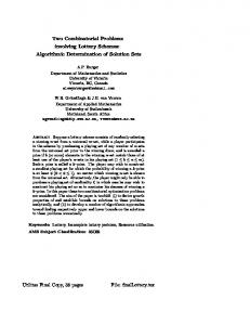
Figure 1.
Control volume.
6
The time stepping (forward Euler) procedure is considered here to be only a means to reach the steady-state. The solution update formula can be given by the following 1t X c (un 0 un ); uni+1 = uni 0 (2.4) k i k h k
i.e. the solution value in each grid point at the new time level can be represented as a combination of the solution values from the previous time level. Applying the TVD concept to characterize the schemes producing non-oscillatory solutions appears to be too restrictive in two dimensions (see [4]). Therefore, we shall follow Spekreijse [16] and use the concept of positivity. De nition 2.1. A scheme is said to be of the positive type if the solution update formula can be written in the form (2.4) in such a way that ck � 0; 8k. Solutions obtained by the means of positive schemes will satisfy a certain maximum principle. 3. Control volume approach Assume that the computational domain is divided into square cells (control volumes) each one associated with the cell-averaged value of the solution approximation (see Fig.1). Integrating Eq.(2.1) over a control volume and applying Gauss theorem we obtain ZZ I ZZ ~ ut dxdy + u� 1 d~n = s dxdy (3.1) C0
@ C0
C0
Since our purpose is to construct a second order accurate advection scheme, it is su�cient to approximate Eq.(3.1) using one- and two- dimensional mid-point quadrature rules. Thus, we obtain 1t u0n+1 = u0n 0 [f+ 0 f0 + g+ 0 g0 ] + s0 1t; (3.2) h where f+ ; f0; g+; g0 are numerical uxes computed at the centers of each side of the control volume C0 . The question is how to compute them in order to obtain an advection scheme with desired properties. In order to simplify our further discussion in this section we assume that (3.3) 0�a�b 2
(a,b) 0
3
(a,b) 0
5
4
a)
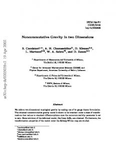
Figure 2.
5 b)
Stencils of the rst order schemes: a) dimensional upwinding: b) N scheme.
3.1. Dimensional upwinding. The simplest example of a positive linear scheme is given by the dimensionally upwinded scheme U with the following uxes f0U = au3 (3.4) g0U = bu5 This corresponds to the following update formula 1t u0n+1 = u0n 0 [b(u0 0 u5 ) + a(u0 0 u3 )] (3.5) h (Fig.2(a) presents the corresponding stencil). However, this scheme su�ers from an excessive numerical di�usion. 3.2. Zero cross-di�usion schemes. Here we present the zero cross-di�usion 2D scheme that was used in [14],[15] for constructing a nonlinear zero cross di�usion positive scheme (see also x3.4 and x3.5). The uxes are f02D = au3 0 12 b(u3 0 u4 ) (3.6) g02D = bu5 0 12 a(u5 0 u4 ) These ux formulae can be motivated by considering the characteristics dy=dx = b=a of (2.3). Speci cally, produce the characteristic through the midpoint of the west face of the control volume, and nd the value of u on it by linear interpolation (or extrapolation) in the interval 34. Multiply this by a to get f0. Similarly the characteristic through the midpoint of the south face carries a value found from the data 45, that gives g0 when multiplied by b. The additional terms found in these
uxes when compared with the U scheme can be regarded as antidi�usive terms which compensate for the di�usivity of the upwind scheme. It is natural to think of creating a high-resolution scheme by applying limiters to these terms. The update formula for this scheme is b a a 1t b u0n+1 = u0n 0 [ (u0 0 u5 ) 0 (u3 0 u4 ) + (u5 0 u4 ) 0 (u0 0 u3 )] h 2 2 2 2 0 t b a 1 (3.7) = u0n 0 h [ 2 (u3 0 u4 0 u0 + u5) + b(u0 0 u5) + a(u5 0 u4)] (and its stencil is presented in Fig.3(a). This scheme is not of the positive type { the coe�cient multiplying u3 in the update formula is negative in our representative case (3.3). Another defect of this scheme is that it will switch discontinuously when a or b changes sign. 3
3
(a,b) 0
4
5
(a,b) 0
4
a)
5 b)
6
Stencils of the linear zero cross-di�usion schemes. A steady-state solution for the homogeneous advection equation obtained by means of a zero cross di�usion scheme will be second order accurate [14],[5]. It must be noted that there is an arbitrariness in the ux formulae. A term k(u3 0 u4) can be added to f0 , and a term k(u4 0 u5) to g0, without a�ecting the update formula, if k is any constant. In fact, one of the ux values is arbitrary. In the remainder of this paper, we adopt, as in [13], a convention that if b > a then g is always given by the characteristic interpolation (3.6), but if b < a it is f that is found in this way. 3.3. N scheme. A positive, though rst order accurate, modi cation of the scheme given by (3.6) is the following f0N = au3 0 12 min(a; b)(u3 0 u4 ) (3.8) g0N = bu5 0 12 min(a; b)(u5 0 u4 ) or, because of our convention (3.3), f0N = au3 0 12 a(u3 0 u4) (3.9) g0N = bu5 0 12 a(u5 0 u4 ) The corresponding update formula is (Fig.2(b) presents the corresponding stencil) 1t un0 +1 = un0 0 [b(u0 0 u5 ) + a(u5 0 u4 )] (3.10) h This scheme was introduced by Rice and Schnipke [10] and was called the N (narrow) scheme in [14],[15] for its narrow stencil. Analysis in [13] shows that the N scheme is the optimal (in terms of cross di�usion) among the linear positive schemes in two dimensions. It is interesting to note that Raithby's scheme [9] is in fact identical to the 2D scheme for the case b=2 � a � b. However, for 0 � a � b=2 Raithby's scheme would correspond to a blend of the 2D scheme with the N scheme. The weight of the N scheme gradually increases with decreasing of a=b and becomes equal to 1 when a = 0. 3.4. S scheme. In order to combine the positivity property with second order accuracy a nonlinear scheme has to be constructed. A positive zero cross di�usion scheme can be constructed in the way similar to TVD schemes in one dimensions. A \limited" zero cross di�usion correction is added to a rst order accurate positive scheme. Such a scheme was developed in [14],[15] and was called the S scheme. It is a nonlinear modi cation of the scheme (3.6) and is given by the following uxes f0S = f0N 0 12 9(R543)(b 0 a)(u3 0 u4 ) (3.11) gS = gN Figure 3.
0
0
4
(a,b) 0
3
4
(a,b) 0
3
5
4
6
5
a)
Figure 4.
7
b)
Positive (non-linear) zero cross-di�usion schemes: a) S scheme; b) S3 scheme.
The ratio Rijk is de ned by a(u 0 u ) Rijk = 0 i j (3.12) b(uk 0 uj ) Here i; j are some pair of grid points consecutive in the x-direction, and j; k are consecutive in the y -direction. Thus, in smooth regions where the solution is close to convergence, Rijk ' 1. This quantity is an example of a two-dimensional smoothness monitor. In particular a(u 0 u ) R543 = 0 5 4 (3.13) b(u 0 u ) 3
4
and 9(R) is a limiter 1 function [18] having the property 9(1=R) = 9(R)=R. Note that the limiting is applied to the di�erence between the uxes of the 2D and N schemes. 2 b(u0 0 u5 ) + a(u5 0 u4 ) 3 1t 6 + 1 9(R543)(b 0 a)(u3 0 u4) 77 u0n+1 = u0n 0 6 (3.14) 5 h 4 2 0 12 9(R650)(b 0 a)(u0 0 u5) Using the following identity (3.15) 9(R543)b(u3 0 u4) � 0 9(RR543543) a(u5 0 u4) we can rewrite (3.14) as follows 2 3 � � 1 9(R650) + 1 9(R ) (u0 0 u5 ) b a 0 0 ( ) 1 2 2 R 1t 4 7 un0 +1 = un0 0 6 (3.16) � � 5 b a 0 ( ) R 9( ) h +a 1 0 12 R (u0 0 u4) b It is clear from (3.16) that the S scheme is of the positive type if (3.17) 0 � 9(RR) � 2; 0 � 9(R) � 2: It was also shown in [14],[15] that the S scheme is second order accurate for a steady-state solution 543 543
543 543
1 For any 9 of this form, we can write 9( ) = ( ) = ( ) = 9( ), where is some averaging function having the symmetry property ( ) = ( ). The forms involving are preferable for coding, because they do not break down when 0. P =Q
M P; Q =Q
M P; Q
P ' Q '
5
M Q; P =Q
M Q; P
P =Q 1
Q=P
M
M
of a homogeneous advection equation (i.e. it has a zero cross di�usion) if 9 is Lipschitz continuous and (3.18) 9(1) = 1: Remark 3.1. The S scheme relies on a 5-point stencil (see Fig.4(a)) - just one point more than the linear zero cross-di�usion scheme (3.6). This one extra point was needed to achieve positivity. It is remarkable that the choice of limiter function in order to obtain a positive scheme with zero cross-di�usion is dictated by relations (3.17) and (3.18) which are identical to those arising when constructing one-dimensional TVD-type schemes. Therefore, most of the limiters used in one dimension (see [18]) can be used in the present context as well. Remark 3.2. Another zero cross di�usion scheme was presented by Koren [7] f0T = f0N + 12 a(bb0a) (u5 0 u4 ) (3.19) g0T = g0N The update formula is 2 1 a(b+a) (u5 0 u4) 3 2 b 7 1 t6 6 n n +1 (3.20) + b(u0 0 u5) 7 u0 = u 0 0 6 7 5 h 4 a(b0a) 1 + 2 b (u6 0 u5) The advantage of this scheme is that it switches continuously when a changes sign. It can be easily seen that this scheme is identical to the one-dimensional Lax-Wendro� scheme, assuming that y is the time-like direction. A detailed analysis of the class of zero cross di�usion schemes was done by Hirsch [5]. It is also proved there that a linear scheme with zero cross di�usion cannot be of the positive type, thus generalizing Godunov's theorem to two dimensions. Remark 3.3. An alternative route to a positive zero cross di�usion scheme is through the nonlinear modi cation of the scheme (3.19) f0T = f0N + 12 9(RR ) a(bb0a) (u5 0 u4 ) (3.21) g0T = g0N : However, it is easy to see using (3.15) and assuming a symmetry property for the limiter, i.e. 9(R) � 9( 1 ) (3.22) 543 543
R
R
(and most of the commonly used limiters are symmetric, see [18]), that the scheme (3.21) is identical to the S scheme. Remark 3.4. The choice of the ratio that the limiter function can rely on is non-unique. For instance, the upwind positive scheme with zero cross-di�usion presented by Hirsch & Van Ransbeeck [6] has a limiter function with the following ratio as its argument a(u 0 u ) (3.23) R034 = 0 0 3 b(u3 0 u4) 6
3.5. S3 scheme. One of the main objectives of this work is to establish links between the control volume and uctuation-splitting approaches towards the construction of the truly two-dimensional advection schemes. It is important for this purpose to introduce the scheme S3 which has a more `triangular avor'. The limiter schemes above are based on ratios Rijk of gradients in orthogonal 3 directions. Now we introduce the ratio Rijk , de ned as 0a(ui 0 uj ) R3ijk = (3.24) (b 0 a)(uk 0 uj ) j; k are adjacent along a diagonal. The fraction has been normalized so where the pair of points 3 that we still have Rijk ' 1 for smooth, nearly steady solutions. The S 3 scheme can be de ned by the following numerical uxes 3 )(b 0 a)(u3 0 u4 ) f0S33 = f0N 0 12 9(R043 : (3.25) g0S = g0N with 3 = 0 a(u0 0 u4) ): R043 (3.26) (b 0 a)(u3 0 u4)
The update formula in this case is (the stencil is presented in Fig.4(b)) 2 b(u0 0 u5 ) + a(u5 0 u4 ) 3 1t 6 + 1 9(R043)(b 0 a)(u3 0 u4) 77 u0n+1 = u0n 0 6 (3.27) 5 h 4 2 0 12 9(R750)(b 0 a)(u0 0 u5)] Note that the following identity holds (3.28) 9(R043)(b 0 a)(u3 0 u4) � 0 9(R043) a(u0 0 u4):
R043 Lemma 3.5. If the limiter 9 = 9(R) satis es the following inequality (3.29) 0 � 9(RR) � 2; 0 � 9(R) � 2: then the S3 scheme is of positive type.
Using the identity (3.28) the update formula for the S3 scheme can be rewritten as follows 0 2 1 9(R750)1 (u0 0 u5 ) 3 0 0 b a ( ) 1 2 1t 5 � � un0 +1 = un0 0 4 (3.30) h +a 1 0 12 9(RR ) (u0 0 u4) It is obvious from (3.30) that the scheme is positive if the inequality (3.29) holds. Lemma 3.6. If 9(R) is Lipschitz continuous and (3.31) 9(1) = 1; Proof.
043 043
then the S3 scheme has a zero cross di�usion.
This lemma is a simple corollary of Lemma A.1 concerning the more general scheme constructed for the inhomogeneous equation. Proof.
7
V2 1 JJ 3� J n2 3 ~ J 3 J E1 J 3 1 J 3 1HH J3 H 1 3J HH E3 1 HH 3 �J 1 3� �H J 1 � 3 HH J HJH � 3 1 � 1 X 3 X JHH XX �� 3 XXX V3 n1 j~ H J H � XX3X J � XX � XXX J � XX J E + � 2 X ~n 1 1 1 1
3
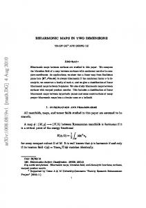
Figure 5.
V1
Illustration for construction of uctuation-splitting schemes.
4. Fluctuation splitting approach In this section we present a brief description of a uctuation splitting approach. For more details see [3],[12],[17]. The schemes are designed for use on unstructured grids and their description is initially given in that context. Later, to compare with the control-volume approach, we specialize to structured grids, and later still we reconsider the general case. Consider a numerical solution of the two dimensional linear constant coe�cient advection equation ~ u = s: ut + ~� 1 r (4.1) The grid is taken to be an arbitrary triangulation of the domain. A typical element T of such a grid is shown on Fig.5. The integral of ut over the triangle T is called the \ uctuation" ZZ T � = ut dxdy: (4.2) T Taking into account Eq.(4.1) and applying Gauss' theorem we obtain I ZZ T ~ � = u� 1 d~n 0 s dxdy; (4.3) @T T where @T is the boundary of the triangle T and d~n is the inward scaled normal to an element of the boundary. Assuming that the source term s varies linearly within triangle T we get ZZ 3 1 X �T = s dxdy = ST si ; (4.4) 3 i=1 T where ST is the area of the triangle T . We shall return to the inhomogeneous case in Appendix B. Here we assume that s � 0 (and therefore �T = 0). ~ u = 0: ut + ~� 1 r (4.5) Assuming also that u varies linearly within triangle T we get 1 1 1 �T = (u1 + u2 )~� 1 ~n3 + (u2 + u3)~� 1 ~n1 + (u1 + u3)~� 1 ~n2 ; (4.6) 2 2 2 8
Vi
Si
Figure 6.
Median dual cell.
where 1 (4.7) ki = ~� 1 ~ni 2 and ~ni is the inward normal to the side Ei scaled with its length. Note that 3 X
(4.8)
i=1
and therefore (4.9)
3 X i=1
This allows (4.6) to be rearranged as (4.10)
�T
~ni = 0 ki = 0:
=0
3 X i=1
k i ui :
Several alternative expressions can be obtained for �T using (4.9), for example, �T = 0k2(u2 0 u1 ) 0 k3 (u3 0 u1) = 0k3(u3 0 u2) 0 k1(u1 0 u2) (4.11) = 0k1(u1 0 u3) 0 k2(u2 0 u3) The computed uctuation should then be distributed (split) among the vertices of the triangle T (4.12) Si ui := Si ui + �Ti 1t�T ; i = 1; 2; 3; where Si is one-third the area of all the triangles having Vi as a vertex (the area of so-called median dual cell of area Si around i, see Fig.6) and (4.13)
3 X i=1
�Ti
= 1:
The latter is necessary for the discretization to be conservative (see [3]). After adding contributions from all the triangles T having a common vertex at point i, we obtain the following scheme 1t X �T � (4.14) uni+1 = uni + i T S 9
i T
V2 B
� � 1 � � � B � � � ~� �B��� � � B � B � � B BB�� B
V1
Figure 7.
V2
� V3
� � BB � B �� 1 � B � � � B ~� ��� � B ���� B � 1 � B � � � � � B � �� V3 ��
~�
V1
(a) Type I triangle (b) Type II triangle Two possible triangle orientation with respect to the ow direction.
We assume here that each triangle sends contributions to its own vertices only. Therefore, the resulting scheme for ui has a compact stencil restricted to at most the immediate neighbours of ui. The remaining question is how to chose �Ti . An additional consideration is positivity of the constructed scheme. We will de ne a more restrictive condition of local positivity that requires contributions of each triangle separately to be positive. De nition 4.1. In equation(4.12) choose from the preceding list the ith de nition of �T , so that Si ui := Si ui 0 �i [kj (uj 0 ui ) + kk (uk 0 ui )]: (4.15) Then the scheme is said to be locally positive if the three quantities 0�i kj 1t; 0�i kk1t; 1 + �i(kj + kk )1t are all positive This condition is easier to implement because it retains the basic property of a uctuationsplitting scheme that all triangles can be processed without reference to any other data. However, it is more restrictive than necessary because it does not recognise that compensating changes from other triangles may restore positivity. It is the condition currently used in design of uctuation splitting schemes. Application of the non-local positivity condition may allow addition of arti cial compression to the scheme. This will be discussed in x5.2. De nition 4.2. The uctuation-splitting scheme is called linearity preserving if whenever the uctuation on the triangle T vanishes then the scheme leads to a zero update in each of the three vertices of the triangle. It was observed by Deconinck et al [3] that linearity-preserving schemes give solutions that are second-order accurate in the steady state. 4.1. N scheme. This linear, positive, uctuation splitting scheme is called the N scheme because it was found by Roe [12] that it is closely related to the control volume N scheme. (We shall return to this point in x5.1.1). Note that there exist two possibilities regarding ki for i = 1; 2; 3 (because of Eq.(4.9)): either one of them is positive and the rest are negative or two of them are positive and one negative. These two situations correspond to a triangle with either one in ow face or two in ow faces. Without loss of generality we can consider the following two cases (see Fig.7) (a) : k1 < 0; k2 < 0; k3 > 0, (b) : k1 > 0; k2 > 0; k3 < 0. 10
V2 @ @ 3 @ 3
3
3
u =const
@
@
@@
� �
�u �
�
3 � 3
1� � � 3
�� �~ � 3 ��� 3 ~ � � �
V33� �
@ � @ @ � R� @ �n �~ � 3 3
=const
@@ @@ @
V1
Construction of the NN scheme. The obvious choice for the rst case (Type I triangle) is to send the entire uctuation to the downstream vertex 3 (i.e. setting �T1 = �T2 = 0; �T3 = 1 ) (4.16) S3 un3 +1 = S3 un3 0 1t[k1(u1 0 u3 ) + k2(u2 0 u3 )] Although interesting schemes can be created that do not follow this rule, we will assume for the remainder of this paper that all Type I triangles are dealt with like this. Case (b) is more complicated. If the uctuation is distributed according to the following formulae S1 un1 +1 = S1 un1 0 1t[k1(u1 0 u3 )] (4.17) S2 un2 +1 = S2 un2 0 1t[k2(u2 0 u3 )] the resulting scheme is obviously positive and this will de ne the N sceme. Strong convergence of the N scheme on general triangulations is proved by Perthame [8]. However, it does not have the LP property. This is because the contributions to the residuals at both vertices 1 and 2 may be di�erent from zero even if the uctuation on triangle T vanishes. 4.2. NN scheme. It was pointed out in [11],[3],[12] that replacing the advection velocity ~� by its normal to the level lines component ~�n normal to the level lines (or tangential to the gradient direction) of u within triangle T ~ ~�n = (~� 1 r ~ u) 1 ru (4.18) jr~ uj2 does not a�ect the residual. It is also obvious that substituting the advection velocity by the following ~�3 = ~�n + �~� (4.19) does not a�ect the residual either. De ning 1 ki3 = ~�3 1 ~ni (4.20) 2 and S1un1 +1 = S1 un1 0 1t[k13 (u1 0 u3 )] (4.21) S2un2 +1 = S2 un2 0 1t[k23 (u2 0 u3 )] one can observe that if � = 0, the NN scheme (4.21) will be linearity preserving. This is because ~�n vanishes at the steady state (and therefore k13 and k23 vanish in this case). However, vector ~�n may extend out of triangle T (Fig.8). Therefore, the scheme in this case is not positive, i.e. one of Figure 8.
11
the k's in (4.21) will be negative. To obtain positivity of the scheme in this case � should be taken such that the vector ~�3 will be directed along the face of triangle T . This means that the entire residual should be sent to only one of the out ow nodes. Because the e�ective advection speed is data dependent (when � = 0 it is the drift velocity of the contours) the NN scheme is nonlinear in a way that permits it to escape Godunov's Theorem. Although the mechanism involved appears very di�erent from that employed by limiter schemes, we will see in the next section that a uni cation is possible. It was pointed out in [3] that when the solution is almost a constant, the expression for ~�n (4.18) becomes ill-de ned, which may a�ect the convergence. A way to overcome this di�culty suggested in [3] was to switch gradually from ~�3 to ~� in regions where the gradients are small. 4.3. Level scheme. It was argued by Roe in [12] that the NN scheme is not optimal in terms of the maximal allowed time step and another scheme for Type II triangles was suggested there. This scheme was later named the Level scheme. A brief description of the algorithm is given here. The reader is referred to [12] for the complete derivation. The residual is distributed among the nodes according to the following formulae: S1u1n+1 = S1u1n + 1t�1 �T (4.22) S2u2n+1 = S2u2n + 1t�2 �T It is very interesting for the discussion in x5.1.3 to note that in [12] the following quantity (4.23) 3 = 0 uu12 00 uu33 was suggested to distinguish between two cases (a) : 3 � 0, i.e. the level line passes through triangle T , (b) : 3 < 0, i.e. the level line lies outside of triangle T . In case (a) only one vertex is updated: the vertex that the characteristic line passes closer to it than the level line. In case (b) both vertices are updated. The residual is distributed according to the following formulae �1 = S (u 0Su(u)+0Su(u) 0u ) (4.24) �2 = S (u 0Su(u)+0Su(u) 0u ) This choice of �'s is argued in [12] to be optimal in terms of the maximal allowed time step. Also, this choice preserves the direction of the level lines; hence the name of the scheme. However, Deconinck [1] has observed that the Level scheme may switch discontinuously if ~� is almost parallel to one side of the triangle, say side 1, but (u2 0 u3 )=(u1 0 u3) > 0. This demonstrates that 3 was an unhappy choice of parameter. 1
1
1
1
1
2
3
3
1
2
2
2
3
3
2
3
2
3
5. Unified approach It is shown in this section that there is more in common between the two previously reviewed approaches than just a philosophy to make constructive use of nonlinearity. In fact the uctuation splitting methodology and control volume compact scheme methodologies can be seen as two dual ways to interpret the same approach. Consider the following scheme on Type II triangles S1u1n+1 = S1 u1n + 1t[k1(u1 0 u3 ) + 9(R132)k2(u2 0 u3 )] (5.1) S2un+1 = S2 un + 1t[k2(u2 0 u3 ) 0 9(R132)k2(u2 0 u3 )] 2
2
12
where Rijk now compares contributions to the uctuation from two sides of the triangle, i.e. k (u 0 u ) Rijk = 0 i i j : (5.2) kk (uk 0 uj ) Again, we have Rijk ' 1 for smooth, nearly steady ow. k (u 0 u ) R132 = 0 1 1 3 (5.3) k2 (u2 0 u3) The conservation property of this scheme is obvious from (5.1). We have the identity (5.4) 9(R132)k2(u2 0 u3) � 0 9(RR132132) k1(u1 0 u3) Theorem 5.1. If the limiter 9(R) satis es the following inequality (5.5) 0 � 9(RR) � 1; 0 � 9(R) � 1; then the NNL scheme is (locally) positive. Proof. Using the identity (5.4) the scheme (5.1) can be rewritten in the following form 132 ) S1 un1 +1 = S1un1 + 1t[1 0 9(RR132 ]k1(u1 0 u3) (5.6) n +1 S2 u2 = S2un2 + 1t[1 0 9(R132)]k2(u2 0 u3)
It can be concluded from the latter that the NNL scheme is positive if inequality (5.5) holds. Remark 5.2. By contrast to the control volume schemes, it is here possible only to use limiters for which the upper bound on 9; 9=R, is equal to 1.0 rather than 2.0. That is, the limiter cannot be compressive. We show later that compressive limiters can be allowed within the uctuation splitting scheme given su�cient information about mesh connectivity.
Theorem 5.3. The NNL scheme is linearity preserving if
(5.7)
j9(R) 0 1j < C jR 0 1j:
for some positive constant C . Proof. We have S1un1 +1 0 S1 un1 = �u1 = 1t[k1(u1 0 u3 ) + 9(R132)k2(u2 0 u3 )] (5.8) 132 ) S2u2n+1 0 S2 u2n = �u2 = 1t[k2(u2 0 u3 ) + 9(RR132 k1 (u1 0 u3 )] We wish to show that if P + Q = 0 then �u1 = �u2 = 0, or equivalently j�u1 0 �u2j < K j�u1 + �u2j; for some positive constant K . Now, if j9 0 1j < C jR 0 1j
= P + 9(R)Q = Q 0 9(R)Q
then
(5.9)
2j9 0 1jjQj jP + Qj + 2j9 0 1jjQj jP + Q + 2(9 0 1)Qj jP 0 Q + 29Qj
< < <