Research Article www.acsami.org
Unique Core−Shell Nanorod Arrays with Polyaniline Deposited into Mesoporous NiCo2O4 Support for High-Performance Supercapacitor Electrodes Nawishta Jabeen,†,‡ Qiuying Xia,†,‡ Mei Yang,*,†,‡ and Hui Xia*,†,‡ †
School of Materials Science and Engineering and ‡HerbertGleiter Institute of Nanoscience, Nanjing University of Science and Technology, Nanjing 210094, China S Supporting Information *
ABSTRACT: Polyaniline (PANI), one of the most attractive conducting polymers for supercapacitors, demonstrates a great potential as high performance pseudocapacitor materials. However, the poor cycle life owing to structural instability remains as the major hurdle for its practical application; hence, making the structure-to-performance design on the PANI-based supercapacitors is highly desirable. In this work, unique core−shell NiCo2O4@PANI nanorod arrays (NRAs) are rationally designed and employed as the electrode material for supercapacitors. With highly porous NiCo2O4 as the conductive core and strain buffer support and nanoscale PANI layer as the electrochemically active component, such a heterostructure achieves favorably high capacitance while maintaining good cycling stability and rate capability. By adopting the optimally uniform and intimate coating of PANI, the fabricated electrode exhibits a high specific capacitance of 901 F g−1 at 1 A g−1 in 1 M H2SO4 electrolyte and outstanding capacitance retention of ∼91% after 3000 cycles at a high current density of 10 A g−1, which is superior to the electrochemical performance of most reported PANI-based pseudocapacitors in literature. The enhanced electrochemical performance demonstrates the complementary contributions of both componential structures in the hybrid electrode design. Also, this work propels a new direction of utilizing porous matrix as the highly effective support for polymers toward efficient energy storage. KEYWORDS: NiCo2O4, PANI, NiCo2O4@PANI, hierarchical, core−shell, supercapacitors
■
INTRODUCTION
Because of the low cost, facile synthesis, controllable electrical conductivity, and high theoretical capacitance (up to 3407 F g−1), polyaniline (PANI) has attracted intensive attention among pseudocapacitive materials.9−13 Nevertheless, PANI suffers from poor mechanical stability and poor cycling stability because of large volumetric swelling and shrinking during doping/dedoping process upon charge/discharge cycling. Moreover, the electrical conductivity of PANI becomes much lower at dedoped state, which causes large electrode polarization and poor rate capability.14 To improve the poor cycling stability of PANI, inorganic materials including metal oxides and carbon have been combined with PANI to make PANI-based composites, where the inorganic component can function as strain buffer to improve the mechanical stability. Among them, the core−shell structures are proven to be particularly advantageous. First, the core−shell electrode can achieve synergetic improvements from intrinsic properties of each component such as better electrical conductivity, greater electrochemical reversibility, shorter ionic transport, and
Owing to the excellent properties such as fast charge−discharge rate, high power density, low maintenance cost, and long service life, supercapacitors have attracted considerable attention as high-power energy storage devices in various applications.1 In matching with the growing developments in backup power sources, portable electronics devices, renewable energy power plants, and electric vehicles, further improvement in energy density and power density for supercapacitors is imperative.2−4 The key objective is to fabricate outstanding electrode materials with simultaneous combination of large specific capacitance, high power delivery, and good cycling stability.5 Regarding the energy storage mechanism, supercapacitors are further divided into two categories: electrochemical double-layer capacitor (EDLC) arising from charge accumulation in the electrode/electrolyte interface, and pseudocapacitor based on the fast and reversible redox reactions at electrochemically active sites.6−8 Normally, pseudocapacitors can deliver capacitance 10-times larger than EDLCs within the same specific surface area, wherein conducting polymers and metal oxides are typical pseudocapacitive electrode materials. © 2016 American Chemical Society
Received: January 7, 2016 Accepted: February 18, 2016 Published: February 18, 2016 6093
DOI: 10.1021/acsami.6b00207 ACS Appl. Mater. Interfaces 2016, 8, 6093−6100
Research Article
ACS Applied Materials & Interfaces
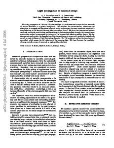
the numerous pores of the NiCo2O4 nanorod arrays so that the porous support can better accommodate the strain and stabilize PANI with improved integrity of the electrode. Moreover, the NiCo2O4 support is highly conductive, which provides fast electron transport paths between PANI and current collector, resulting in small electrode polarization and excellent power capability. The homogeneous coating of PANI maintains high activity in acidic electrolyte, which could also shield the NiCo2O4 structure from dissolution and collapse by serving as intimate protective shell in such environment.25 Thereby, the NiCo2O4@PANI NRAs electrode exhibits superb capacitive behavior as well as good cycling stability due to the rational hybrid electrode design. This work introduces a novel strategy for designing of conducting polymers-based pseudocapacitors with desirable energy storage performance.
improved mechanical stability and cycling stability. Second, its unique coating has the potential to decline the surface energy effectively, which will reduce the aggregation possibilities of active materials as well as relieve side reactions between electrolyte and electrode, bringing in better reversibility and cycling stability of electrodes.15 Previously, the use of inorganic materials such as metal oxides and carbon as supporting materials has been proved as an effective approach for the improvement of cycling degradation problems and capacitive performance of conducting polymers.16,17 For example, ordered TiO2 nanotube arrays are utilized as the excellent core material for PANI.18 Meanwhile, Xia et al. found that PANI based supercapacitors using TiN nanowire/carbon cloth supports possess excellent cycle stability and high power density.19 By using graphene−mesoporous silica composite as supporting template, Wang et al. introduced in situ polymerization method to grow mesoporous polyaniline film on ultrathin graphene sheets. The fabricated electrode delivered a maximum capacitance of 749 F g−1 at 0.5 A g−1, and improved capacitance retention of 88% at 5 A g−1 after 1000 cycles was obtained.20 Cho et al. fabricated highly porous solution processed polyaniline thin films, which can reach only 361 F g−1 at 0.25 A g−1.21 However, the improvement in cycling stability for PANI-based electrode materials is still very limited in previous works. Most importantly, it is so far a great challenge to achieve desirable cycling performance while maintaining high capacitance of the PANI-based electrode materials. Herein, we have reported a novel approach to fabricate core−shell NiCo2O4@PANI nanorod arrays (NRAs) for stable PANI-based electrodes with noticeably improved electrochemical performance. As illustrated in Scheme 1, highly
■
EXPERIMENTAL SECTION
Synthesis of NiCo2O4 NRAs. All the reagents were of analytical grade and directly used without further purification. Prior to growth, commercial carbon clothes (2 × 2 cm2 in square shape) were cleaned by sonication in 1 M HCl solution, acetone, deionized water, and ethanol for 20 min each and dried at 60 °C for 2 h. NiCo2O4 NRAs were grown on the carbon cloth by a hydrothermal method. In a typical synthesis, Ni(NO3)2·6H2O (4 mmol), Co(NO3)2·6H2O (8 mmol), and urea (15 mmol) were dissolved into 75 mL of deionized water and stirred to form a clear pink solution. After 15 min of stirring, the solution was transferred into a 100 mL Teflon-lined stainless autoclave. The well-cleaned carbon cloth was placed in the solution, and the autoclave was kept at 120 °C for 6 h. After it was cooled down to room temperature, the product was taken out and washed with deionized water and ethanol. Finally, the sample was annealed at 380 °C in air for 2 h for further characterization. Synthesis of NiCo2O4@PANI Core−Shell Structure NRAs. Electrodeposition was performed at room temperature in a threeelectrode cell using an Ag/AgCl reference electrode, a Pt foil counter electrode, and the NiCo2O4 NRAs as the working electrode. An aqueous solution of 0.1 M aniline monomer and 1 M H2SO4 was used as the electrolyte. Electrochemical polymerization of aniline was performed potentiostatically at a constant voltage of 0.8 V on the NiCo2O4 NRAs for different times from 1−6 min. After electrodeposition, the obtained samples were washed with distilled water and ethanol for several times. For comparison, PANI nanorods were directly electrodeposited on carbon cloth (see Figure S1 in Supporting Information). After successful PANI deposition for 1, 2, 3, 4, 5, and 6 min, the mass loading was determined as 0.61, 0.69, 0.78, 0.89, 1.21, and 1.39 mg cm−2, respectively. The average thickness of PANI layer is estimated as 10 nm per minute. Materials Characterization. X-ray diffraction (XRD, Shimadzu Xray diffractormeter 6000, Cu Kα radiation), Fourier transform infrared spectroscopy (FTIR, spectra Nicolet Nexus 470 spectrometer), and Raman spectroscopy (Jobin-Yvon T6400 Micro-Raman system) were performed to investigate the crystallographic information and phase purity of the samples. Morphological and microstructure investigations were performed using field-emission scanning electron microscopy (FESEM, Hitachi S4300), transmission electron microscopy (TEM, FEI Philips CM300 UT/FEG), and high-resolution transmission electron microscopy (HRTEM). A Tecnai G2 F30 S-TWIN microscope operated at 300 kV was employed to reveal the core− shell structure using the scanning transmission electron microscope (STEM) mode with energy-dispersive X-ray spectroscopy (EDS) mapping. The elemental compositions of the samples were analyzed with EDS attached to the FESEM. Electrochemical Measurements. The electrochemical performances of the samples were measured in a standard three-electrode setup. CHI760C electrochemical workstation (Chenhua, Shanghai) was employed to perform cyclic voltammetry and galvanostatic charge−discharge measurements in 1 M H2SO4 aqueous solution. Cyclic voltamemetary was carried out within the voltage range of
Scheme 1. Schematic Illustration of the Synthetic Procedure for NiCo2O4@PANI NRAs
porous NiCo2O4 NRAs, assembled by numerous nanoparticles, were first grown on the carbon cloth by a hydrothermal process, followed by a uniform coating of PANI onto the NiCo2O4 via electrodeposition at a constant voltage. Owing to the high conductivity of 62 S cm−1, porous structure, and good strain accommodation in core−shell structures,22−24 NiCo2O4 NRAs are selected as the pivotal core component for the heterostructure design. Different from previous works on designing the core−shell structured electrode, a porous core instead of a solid core was utilized in the present work, which can further improve the cycling stability of PANI. In such core−shell structure, the nanoscale PANI can be deposited into 6094
DOI: 10.1021/acsami.6b00207 ACS Appl. Mater. Interfaces 2016, 8, 6093−6100
Research Article
ACS Applied Materials & Interfaces −0.15−0.8 V versus Ag/AgCl. Galvanostatic charge−discharge measurements were performed within a voltage range of 0−0.8 V versus Ag/AgCl at different current densities. For statistical analysis, each measurement has been repeated three times on three samples to get the average data and deviation. Electrochemical impedance spectroscopy (EIS) was measured by applying an AC voltage of 5 mV amplitude in a frequency range within 0.01 Hz−100 kHz.
component. The protonation process, resulted from polysemiquinone radical formation, was intrinsically linked with the peak 1339 cm−1, which proves the conducting state of asprepared PANI component.29 The peaks at 542 and 596 cm−1 can be assigned to amine deformation and ring deformation, respectively.30 Above all, Raman results confirm the formation of NiCo2O4@PANI composite. Particularly, the enhancement of C element signal in EDS spectrum demonstrates successful coating of PANI (see Figure S2a,b in Supporting Information). In the FTIR spectrum (see Figure S3 in Supporting Information), the peaks at 1566 and 1482 cm−1 characteristically correspond well to the C−C stretching of the quinonoid (Q) and benzenoid (N) rings of PANI, respectively, further affirming the formation of PANI. The morphologies of the as-synthesized NiCo2O4 NRAs and NiCo2O4@PANI NRAs are characterized by FESEM. Figure 2,
■
RESULTS AND DISCUSSION The crystalline structure and phase purity of the samples were first characterized by XRD. Figure 1, panel a shows the
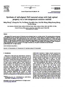
Figure 2. (a) FESEM image of carbon fiber loaded with NiCo2O4 NRAs. (b, c) Locally enlarged views of the carbon fibers after conformal growth of NiCo2O4 NRAs. (d) FESEM image of carbon fiber after the coating of PANI on NiCo2O4 nanorods and (e, f) highmagnification images of the in situ growth of NiCo2O4@PANI NRAs.
panels a−c show the FESEM images of NiCo2O4 NRAs at different magnifications, indicating the uniquely uniform growth of the NiCo2O4 NRAs at large scale. The focused observation of an individual carbon fiber suggests that numerous NiCo2O4 nanorods grow tidily on the surface of the carbon fiber (Figure 2a). Figure 2, panel b reveals that the as-synthesized NiCo2O4 nanorods are homogeneously aligned and separated apart. Furthermore, such structures are believed to possess high structural integrity and sufficiently large surface area to stabilize the cycling stability. High magnification image (Figure 2c) presents the porous nature of the NiCo2O4 nanorods, which could function as a buffer support for PANI with expansion and contraction. It can also be observed that these nanorods possess sharp tips-like needles, which are attributed to the depletion of precursor during the growth process. Figure 2, panel d shows an individual carbon nanofiber supported NiCo2O4@PANI NRAs. The length of NiCo2O4 nanorods is up to several microns, and the diameter becomes larger (average ∼200 nm) after the growth of PANI layer (Figure 2e). Figure 2, panel f shows “skin-like” PANI networks coated on the NiCo2O4 NRAs, with the needle ends transformed to uniform round shapes, which ensure close contact between the PANI active material and highly conductive NiCo2O4 nanorods. Typical textures of the NiCo2O4@PANI NRAs are displayed in Figure 3, panel a. As revealed, the surface of NiCo2O4 NRAs is fully covered with a thin PANI film, demonstrating the typical core−shell heterostructure. More details can be illustrated in the magnified TEM images (Figure 3b,c) of a separate NiCo2O4 nanorod, wherein the thickness of the PANI shell is
Figure 1. (a) XRD patterns and (b) Raman spectra of the pure NiCo2O4 NRAs and the NiCo2O4@PANI NRAs. CC denotes carbon cloth.
comparison of XRD patterns of the pure NiCo2O4 NRAs and NiCo2O4@PANI NRAs. The diffraction peaks for both samples at the 2θ values of 19.3, 31.2, 36.8, 38.5, 44.8, 55.8, 59.3, and 65.2° can be indexed as the (111), (220), (311), (222), (400), (422), (511), and (440) crystal planes of cubic NiCo2O4 with spinel crystalline structure (JCPDS card no. 73−1702). As for the NiCo2O4@PANI NRAs, similar diffraction peaks of NiCo2O4 can be observed without detection of PANI peaks, implying a noncrystalline state for PANI in the core−shell composite. Moreover, the integration of PANI has no obvious changing effect on the crystallinity of NiCo2O4. Raman spectroscopy was further performed to investigate the structure and phase composition of the samples. Figure 1, panel b presents the Raman spectra of the pure NiCo2O4 and NiCo2O4@PANI NRAs within the frequency range of 0−2000 cm−1. For pure NiCo2O4 NRAs, three characteristic peaks at 186, 456, and 649 cm−1 correspond to F2g, Eg, and A1g vibration modes of the NiCo2O4, respectively.26 The prominent peaks at 1186, 1339, 1511, and 1581 cm−1 for NiCo2O4@PANI NRAs can be attributed to C−H bending of quinoid ring, C−N+ stretching, C−C stretching of the benzene ring, and CC stretching,27,28 confirming the successful incorporation of PANI 6095
DOI: 10.1021/acsami.6b00207 ACS Appl. Mater. Interfaces 2016, 8, 6093−6100
Research Article
ACS Applied Materials & Interfaces
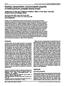
Figure 3. TEM images of (a) the NiCo2O4@PANI NRAs and (b, c) an individual core−shell nanorod. (d) HRTEM image reveals the lattice spacing of the NiCo2O4 support and the filled PANI constituent. (e) High-angle annular dark-field (HAADF) STEM image of a representative nanorod and corresponding element mapping images for the nickel, cobalt, oxygen, carbon, and nitrogen.
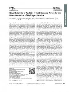
Figure 4. (a) A comparison of CV curves of the NiCo2O4@PANI NRAs, bare carbon cloth, NiCo2O4 NRAs, and pure PANI electrodes at a scan rate of 5 mV s−1. (b) CV curves of NiCo2O4@PANI NRAs at different scan rates of 10, 20, 40, 60, 80, and 100 mV s−1. (c) Charge and discharge curves of the NiCo2O4@PANI NRAs electrode at different current densities of 1, 2, 4, 8, and 10 A g−1. (d) The plot of specific capacitances versus current densities for the NiCo2O4@PANI NRAs electrode.
estimated to be about 40−50 nm. Because of highly mesoporous architectures of the NiCo2O4 nanorod support (see Figure S4 in the Supporting Information), the electrochemically active PANI constituent not only covers the surface, but also fills in the mesopores (Figure 3c,d), which results in a novel core−shell heterostructure. These well-organized NiCo2O4 NRAs with intimate electrical contact can provide powerful buffer to withstand the volume change of PANI during ion intercalation. Besides, this unique core−shell structure endows the PANI with efficiently large surface area and facile access to electrolyte ions. The HRTEM image in Figure 3, panel d displays clear lattice fringes with a d−spacing of 0.28 nm, corresponding to the (220) planes of spinel NiCo2O4. The SAED pattern of as-prepared NiCo2O4 NRAs (see Figure S4d in the Supporting Information) shows five
diffraction rings, further confirming the spinel NiCo2O4 phase without impurity. A representative STEM image of a single NiCo2O4@PANI nanorod and corresponding mappings for Ni, Co, N, C, and O elements are shown in Figure 3, panel e. It can be observed that the Co and Ni elements are mainly located in the core area, while N, C, and O elements are distributed throughout the nanorod area, confirming that active PANI is not only deposited on the surface of NiCo2O4 nanorods, but also well dispersed inside NiCo2O4 naorods by filling the pores. To investigate the pseudocapacitive behavior of different samples, CV measurements were carried out in the potential range between −0.15 and 0.8 V (versus Ag/AgCl) in 1 M H2SO4 aqueous electrolyte. Figure 4, panel a presents the comparison of typical CV curves of the carbon cloth, NiCo2O4 NRAs, pure PANI, and NiCo2O4@PANI NRAs electrodes at a 6096
DOI: 10.1021/acsami.6b00207 ACS Appl. Mater. Interfaces 2016, 8, 6093−6100
Research Article
ACS Applied Materials & Interfaces
Table 1. Comparison of Electrochemical Performance for PANI-Based Electrodes in Acidic Aqueous Electrolytes PANI-based electrodes PANI/titania nanotubes
potential range (V vs Ag/AgCl or SCE)
specific capacitance (F g−1)
capacitance retention (%)
reference (year)
−0.2 to 1 V
732 at 1 A g−1
2000 86% 200 97% 200 95% 1000 88% 3000 77% 1000 85% 1000 96% 2000 70% 3000 91%
33 (2011) 34 (2014) 34 (2014) 35 (2014) 36 (2014) 37 (2015) 38 (2015) 39 2015 this work
Polyaniline/TiO2 core−shell nanowires arrays
0 to 0.6 V
485 at 1 A g−1
Polyaniline/TIN core−shell nanowire arrays
0 to 0.6 V
1064 at 1 A g−1
PANI film/GO nanosheets
−0.2 to 0.8 V
749 at 0.5 A g−1
MoO3/PANI coaxial heterostructure nanobelts
−0.4 to 0.6 V
632 at 1 A g−1
PANI/TiO2Core−shell nanorods
−0.2 to 0.8 V
820 at 1 A g−1
Three-Dimensional Tubular MoS2 /PANI Hybrid
−0.1 to 0.6 V
552 at 0.5 A g−1
Polyaniline/black TiO2 nanotubes
−0.2 to 1.0 V
999 at 0.6 A g−1
PANI@NiCo2O4 core−shell NRAs
901 at 1 A g−1
−0.15 to 0.8 V
scan rate of 5 mV s−1. Though the operating potential range for the NiCo2O4 support can be enlarged in acidic electrolyte (commonly 0−0.5 V in alkaline solution), the responding currents in the CV curves of both pure NiCo2O4 NRAs and bare carbon cloth are very small compared to those of PANI and NiCo2O4@PANI NRAs electrodes (also see Figure S5a in the Supporting Information), indicating the negligible capacitance contribution from carbon cloth and NiCo2O4 in the acid electrolyte. The CV curve of NiCo2O4@PANI NRAs electrode shows redox peaks similar to pure PANI but with higher current density, suggesting that the PANI layer in the heterostructure can deliver much higher capacitance than the pure PANI electrode. In other words, the conductive network and highly porous architecture of NiCo2O4 support endow the active PANI layer with noticeably enhanced electrochemical activity. Figure 4, panel b shows the CV curves of the NiCo2O4@PANI NRAs electrode at different scan rates from 10−100 mV s−1. Even at a high scan rate of 100 mV s−1, the CV curve retains well-defined redox peaks with small polarization, demonstrating excellent electrode kinetics and good rate capability. The first pair of redox peaks (P1/P3 at approximately 0.24/0.07 V) can be ascribed to the transformation between leucoemeraldine and emeraldine states of PANI, and the second pair of redox peaks (P2/P4 at around 0.50/0.48 V) can be attributed to the redox couple of emeraldine/pernigraniline states.31,32 By comparison, the CV curves of the pure PANI electrode exhibit obvious polarization behavior with distorted shape at high scan rates (see Figure S5b in the Supporting Information). The galvanostatic charge−discharge curves are presented in Figure 4, panel c, and measured between 0 to 0.8 V at different current densities. The specific capacitance (Cm) can be calculated by the following eq 1: Cm =
C I × Δt = m ΔV × m
resistance (IR) drop. As displayed in Figure 4, panel d, the average specific capacitances of the NiCo2O4@PANI NRAs electrode are calculated to be 901 ± 41, 865 ± 43, 800 ± 40, 763 ± 38, and 725 ± 37 F g−1 at current densities of 1, 2, 4, 8, and 10 A g−1, respectively, showing superb capacitance retention with the increase of current densities. It is known pseudocapacitance originates from the highly reversible and fast electrochemical redox reactions at superficial active sites, relying on both the ion and electron transport. In this hybrid electrode design, the NiCo2O4 NRAs, as conductive scaffold for PANI, provide large surface area and well-built architecture for loading of electrochemically active component. Therefore, even at the high current density of 10 A g−1, the capacitance retention is still around 80% of the value measured at 1A g−1, suggesting outstanding rate capability, which is in accordance with the CV results. In contrast, the specific capacitance of pure PANI electrode is only about 436 F g−1 at 1 A g−1, which is less than half of that for the NiCo2O4@PANI NRAs electrode (see Figure S5c in the Supporting Information). The inferior performance of pure PANI electrode can be attributed to the poor electrical conductivity at dedoped state, resulting in large ohmic polarization of the electrode and damage to the reversibility of pure PANI electrode. Table 1 summarizes the electrochemical performance of the previously reported PANIbased electrodes in acidic electrolytes.33−39 It is obvious that the present core−shell NiCo2O4@PANI NRAs electrode exhibit superior cycling stability to other reported PANIbased electrodes while maintaining a very high specific capacitance close to the highest values reported in literature, which apparently can be attributed to the unique core−shell structure of the electrode in the present work. The electrochemical utilization of PANI constituent in the hybrid depends on the mass loading of PANI on the NiCo2O4 nanorods. NiCo2O4@PANI NRAs with different mass loadings were prepared by tailoring the electrodeposition time. At a current density of 1 A g−1, specific capacitance increases with the deposition time until it reaches 4 min (see Figure S6a,b in the Supporting Information). After electrodeposition for 1 min, the PANI only manifests slight coating on the NiCo2O4 nanorods with barely a small morphological difference observed
(1)
Where I (A), m (g), and Δt (s) denote the discharge current, mass of active materials, and discharge time, respectively. Cm (F g−1) represents the specific capacitance, and ΔV (V) is the voltage change during the discharge process after internal 6097
DOI: 10.1021/acsami.6b00207 ACS Appl. Mater. Interfaces 2016, 8, 6093−6100
Research Article
ACS Applied Materials & Interfaces
superb cycle performance, the morphology and microstructure of the novel core−shell NiCo2O4@PANI NRAs were further investigated after 500 and 3000 charge−discharge cycles (Figure 6). Generally, the porous NiCo2O4 NRAs show the
for the NRAs (see Figure S7a,b in the Supporting Information). Further augment of the deposition time beyond 4 min leads to a decrease of the capacitance, implying the insufficient utilization of PANI at a large loading amount. As revealed in FESEM images of the 6 min deposition sample (see Figure S7e,f in the Supporting Information), PANI starts to agglomerate at the tips of the NRAs instead of depositing on the nanorod surface. Without direct contact with conductive NiCo2O4 nanorods, these isolated PANI agglomerates cannot be fully utilized, thus leading to a decline of capacitance. In contrast, the 4 min deposition sample possesses both ideal core−shell structure and high structural utilization, representing the optimum electrode design to achieve large specific capacitance and high rate capability. On the basis of the charge/discharge curves, the energy and power densities for the NiCo2O4@PANI NRAs electrode are calculated at various current densities. The obtained Ragone plot for the NiCo2O4@ PANI NRAs electrode is presented in Figure S5d (see Supporting Information) with comparison to previously reported PANI-based composite electrodes. Remarkably, the NiCo2O4@PANI NRAs electrode shows a maximum energy density of ∼81.77 Wh kg−1 at a power density of 399.3 W kg−1. Even at a high power density of 4 kW kg−1, it can deliver the energy density of 64.44 Wh kg−1, demonstrating significantly enhanced energy density and power capability compared to other PANI-based electrodes. Apart from the outstanding rate capability, the NiCo2O4@ PANI NRAs electrode also exhibits excellent cycling performance as well as good Coulombic efficiency. As shown in Figure 5, the average capacitance retention reaches as high as 91 ± 4%
Figure 6. (a, b) FESEM images and (c) corresponding TEM image of the NiCo2O4@PANI NRAs after 500 charge−discharge cycles. (d, e) FESEM images and (f) corresponding TEM image of the NiCo2O4@ PANI NRAs after 3000 charge−discharge cycles.
desirable ability to accommodate the volumetric swelling and shrinking of PANI during doping/dedoping processes. Furthermore, it acts as conductive scaffold to bind the active coating layers and also maintains the electrochemical stability and mechanical integrity between PANI and the NiCo2O4/ carbon cloth substrate, which make the overall morphology perfectly unchanged after 500 repeated cycles. Even after 3000 cycles, the NiCo2O4@PANI NRAs are still strongly attached to the carbon fiber with only slight morphology change caused by the bundling of some nanorods (see Figure S9a,b in Supporting Information). The excellent cycling stability and good rate capability with large specific capacitance make the NiCo2O4@ PANI NRAs a highly promising candidate for practical energy storage devices. EIS measurements were carried out to further understand the superior pseudocapacitive performance of the NiCo2O4@PANI NRAs. Nyquist plots are revealed in Figure 7, and the
Figure 5. Cycle performance of the NiCo2O4@PANI NRAs electrode for 3000 successive charge−discharge cycles at a large current density of 10 A g−1 and corresponding Coulombic efficiency (inset is the typical charge−discharge curves).
at 10 A g−1 after 3000 successive cycles in acidic electrolyte (also see Figure S8 in the Supporting Informaiton), suggesting the superb cycling stability, which is fundamentally attributed to the optimized synergetic effects and rational design of the novel core−shell NiCo2O4@PANI NRAs. The inset in Figure 5 shows typical charge−discharge curves from the 3000 successive cycles. The plots are symmetric regarding charge− discharge process, manifesting no significant structural degradation of the NiCo2O4@PANI NRAs electrode. As summarized in Table 1, the poor cycle life related to structural instability is always the major concern for previously reported PANI-based electrodes. In the present work, the porous NiCo2O4 conductive support and the core−shell heterostructure design significantly improve the structural stability of the PANI-based electrode. To gain deeper understanding of the
Figure 7. Nyquist plots of the NiCo2O4@PANI NRAs and PANI electrodes. Inset is a equivalent circuit for fitting.
equivalent series resistance (ESR, Rs) values for the pure PANI and the NiCo2O4@PANI NRAs electrodes are 1.95 Ω and 1.08 Ω, respectively. These values relate to the intrinsic resistance of active materials, total resistances of the ionic resistance of electrolyte, and contact resistance at the active materials/current collector interface.40 The charge−transfer resistance (Rct) of NiCo2O4@PANI NRAs electrode (0.46 Ω) is almost half of that of the pure PANI electrode (0.98 Ω). This could be attributed to the enhanced electron transport and large surface area of the PANI layer in the core−shell structure, 6098
DOI: 10.1021/acsami.6b00207 ACS Appl. Mater. Interfaces 2016, 8, 6093−6100
Research Article
ACS Applied Materials & Interfaces Notes
which facilitates fast redox reactions in the hybrid electrode. Meanwhile, the almost vertical line in the low frequency region of the NiCo2O4@PANI NRAs electrode confirms the fast ion diffusion and ideal capacitive behavior, resulting in fast electrode kinetics.
The authors declare no competing financial interest.
■
ACKNOWLEDGMENTS This work was supported by National Natural Science Foundation of China (No. 51572129, U1407106), Natural Science Foundation of Jiangsu Province (No. BK20131349), QingLan Project of Jiangsu Province, A Project Funded by the Priority Academic Program Development of Jiangsu Higher Education Institutions (PAPD), and the Fundamental Research Funds for the Central Universities (No. 30915011204).
■
CONCLUSIONS A rational design with a facile synthesis of PANI-based hybrid electrode has been demonstrated by constructing novel core− shell structure using porous NiCo2O4 nanorod arrays as support. The highly porous and conductive configuration of NiCo2O4 core, consisting of numerous nanoparticles, not only provides fast electron transport, but also functions as strain buffer for PANI. Facilitated by the porous feature as well as large surface, controlled deposition of nanoscale PANI onto and into this fascinating architecture can significantly enhance pseudocapacitive performance with fast charge transport and especially superb structural stability, implying the synergetic effect between the two components can further boost the electrochemical performance of the PANI-based electrodes. Briefly, the optimized NiCo2O4@PANI NRAs can attain an extremely high specific capacitance of 901 F g−1 at 1 A g−1 and excellent cycling stability (∼91% capacitance retention after 3000 successive cycles at 10 A g−1). By adopting the highly conductive and porous support, the unique core−shell heterostructure is favorable for the full exertion and utilization of the pseudocapacitive PANI layer, providing an effective strategy toward developing high-performance electrodes for supercapacitors. The provided structure-to-performance design in this work makes further enhancement over most of previous works through building the unique free-standing porous support/polymer core−shell electrode, which may propel an appealing direction of utilizing porous matrix to effectively support electrochemically active polymers for efficient energy storage.
■
■
(1) Miller, J. R.; Simon, P. Electrochemical Capacitors for Energy Management. Science 2008, 321, 651−652. (2) Wang, G. P.; Zhang, L.; Zhang, J. J. A Review of Electrode Materials for Electrochemical Supercapacitors. Chem. Soc. Rev. 2012, 41, 797−828. (3) Qu, Q. T.; Zhu, Y. S.; Gao, X. W.; Wu, Y. P. Core-Shell Structure of Polypyrrole Grown on V2O5 Nanoribbon as High Performance Anode Material for Supercapacitors. Adv. Energy Mater. 2012, 2, 950− 955. (4) Chen, H. C.; Jiang, J. J.; Zhang, L.; Wan, H. Z.; Qi, T.; Xia, D. D.Highly Conductive NiCo2S4 Urchin-Like Nanostructures for HighRate Pseudocapacitors. Nanoscale 2013, 5, 8879−8883. (5) Rakhi, R. B.; Chen, W.; Cha, D.; Alshareef, H. N. Nanostructured Ternary Electrodes for Energy-Storage Applications. Adv. Energy. Mater. 2012, 2, 381−389. (6) Simon, P.; Gogotsi, Y. Materials for Electrochemical Capacitors. Nat. Mater. 2008, 7, 845−854. (7) Zhang, L. L.; Zhao, X. S. Carbon-Based Materials as Supercapacitor Electrodes. Chem. Soc. Rev. 2009, 38, 2520−2531. (8) Inagaki, M.; Konno, H.; Tanaike, O. Carbon Materials for Electrochemical Capacitors. J. Power Sources 2010, 195, 7880−7903. (9) Kuila, B. K.; Nandan, B.; Bohme, M.; Janke, A.; Stamm, M. Vertically Oriented Arrays of Polyaniline Nanorods and Their Super Electrochemical Properties. Chem. Commun. 2009, 65, 5749−5751. (10) Peng, X.; Huo, K. F.; Fu, J. J.; Zhang, X. M.; Gao, B.; Chu, P. K. Coaxial PANI/TiN/PANI Nanotube Arrays for High-Performance Supercapacitor Electrodes. Chem. Commun. 2013, 49, 10172−10174. (11) Chen, W.; Xia, C.; Rakhi, R. B.; Alshareef, H. N. A General Approach toward Enhancement of Pseudocapacitive Performance of Conducting Polymers by Redox-Active Electrolytes. J. Power Sources 2014, 267, 521−526. (12) Xia, X.; Chao, D.; Fan, Z.; Guan, C.; Cao, X.; Zhang, H.; Fan, H. J. A New Type of Porous Graphite Foams and Their Integrated Composites with Oxide/Polymer Core/Shell Nanowires for Supercapacitors: Structural Design, Fabrication, and Full Supercapacitor Demonstrations. Nano Lett. 2014, 14, 1651−1658. (13) Xia, X.; Chao, D.; Qi, X. Y.; Xiong, Q.; Zhang, Y.; Tu, J. P.; Zhang, H.; Fan, H. J. Controllable Growth of Conducting Polymers Shell for Constructing High-Quality Organic/Inorganic Core/Shell Nanostructures and Their Optical-Electrochemical Properties. Nano Lett. 2013, 13, 4562−4568. (14) Meng, C. Z.; Liu, C. H.; Chen, L. Z.; Hu, C. H.; Fan, S. S. Highly Flexible and All-Solid-State Paper Like Polymer Supercapacitors. Nano Lett. 2010, 10, 4025−4031. (15) Yu, Z.; Tetard, L.; Zhai, L.; Thomas, J. Supercapacitor Electrode Materials: Nanostructures from 0 to 3 Dimensions. Energy Environ. Sci. 2015, 8, 702−730. (16) Zhang, J.; Kong, L. B.; Wang, B.; Luo, Y. C.; Kang, L. In-situ Electrochemical Polymerization of Multi-Walled Carbon Nanotube/ Polyaniline Composite Films for Electrochemical Supercapacitors. Synth. Met. 2009, 159, 260−266. (17) Zhang, L. Y.; He, S. J.; Chen, S. L.; Guo, Q. H.; Hou, H. Q. Preparation and Electrochemical Properties of Polyaniline/Carbon Nanofiber Composite Materials. Acta Phys. Chim. Sin. 2010, 26, 3181− 3186.
ASSOCIATED CONTENT
* Supporting Information S
The Supporting Information is available free of charge on the ACS Publications website at DOI: 10.1021/acsami.6b00207. FESEM images of PANI nanorods; EDS spectra of pure NiCo2O4 NRAs and NiCo2O4@PANI NRAs; FTIR patterns of pure NiCo2O4 NRAs and NiCo2O4@PANI NRAs; TEM images of NiCo2O4 NRAs at low and high magnifications; SAED pattern of NiCo2O4 NRAs; CV curves of pure NiCo2O4 NRAs and pure PANI electrodes at different scan rates; charge/discharge curves of the NiCo2O4 and NiCo2O4@PANI electrodes; Ragone plot for NiCo2O4@PANI electrode; specific capacitance as a function of PANI deposition time; specific capacitance histogram at different deposition times; FESEM images of NiCo2O4@PANI NRAs for different electrodeposition times; FESEM images of PANI and NiCo2O4@PANI NRAs electrodes after 3000 charge/discharge cycles (PDF)
■
REFERENCES
AUTHOR INFORMATION
Corresponding Authors
*E-mail:
[email protected]. Phone: (86) 25 84303408. Fax: (86) 25 84303408. *E-mail:
[email protected]. 6099
DOI: 10.1021/acsami.6b00207 ACS Appl. Mater. Interfaces 2016, 8, 6093−6100
Research Article
ACS Applied Materials & Interfaces (18) Gobal, F.; Faraji, M. Electrodeposited Polyaniline on Pd-Loaded TiO2 Nanotubes as Active Material for Electrochemical Supercapacitor. J. Electroanal. Chem. 2013, 691, 51−56. (19) Xia, C.; Xie, Y.; Wang, W.; Du, H. Fabrication and Electrochemical Capacitance of Polyaniline/Titanium Nitride CoreShell Nanowire Arrays. Synth. Met. 2014, 192, 93−100. (20) Wang, Q.; Yan, J.; Fan, Z. J.; Wei, T.; Zhang, M. L.; Jing, X. Y. Mesoporous Polyaniline Film on Ultra-Thin Graphene Sheets for High Performance Supercapacitors. J. Power Sources 2014, 247, 197− 203. (21) Cho, S.; Shin, K. H.; Jang, J. Enhanced Electrochemical Performance of Highly Porous Supercapacitor Electrodes Based on Solution Processed Polyaniline Thin Films. ACS Appl. Mater. Interfaces 2013, 5, 9186−9193. (22) Hu, L. F.; Wu, L. M.; Liao, M. Y.; Hu, X. H.; Fang, X. S. Electrical Transport Properties of Large, Individual NiCo2O4 Nanoplates. Adv. Funct. Mater. 2012, 22, 998−1004. (23) Liu, X. Y.; Shi, S. J.; Li, L.; Zhang, Y. Q.; Tang, H.; Gu, C. D.; Wang, X. L.; Tu, J. P.; Xiong, Q. Hierarchical NiCo2O4@NiCo2O4 Core/Shell Nanoflake Arrays as High-Performance Supercapacitor Materials. ACS Appl. Mater. Interfaces 2013, 5, 8790−8795. (24) Liu, X. Y.; Zhang, Y. Q.; Xia, X. H.; Shi, S. J.; Lu, Y.; Wang, X. L.; Gu, C. D.; Tu, J. P. Self-Assembled Porous NiCo2O4 HeteroStructure Array for Electrochemical Capacitor. J. Power Sources 2013, 239, 157−163. (25) Snook, G. A.; Kao, P.; Best, A. S. Conducting-Polymer-Based Supercapacitor Devices and Electrodes. J. Power Sources 2011, 196, 1− 12. (26) Deng, F.; Yu, L.; Cheng, G.; Lin, T.; Sun, M.; Ye, F.; Li, Y. Synthesis of Ultrathin Mesoporous NiCo2O4 Nanosheets on Carbon Fiber Paper as Integrated High-Performance Electrodes for Supercapacitors. J. Power Sources 2014, 251, 202−207. (27) Huang, F.; Vanhaecke, E.; Chen, D. In Situ Polymerization and Characterizations of Polyaniline on MWCNT Powders and Aligned MWCNT Films. Catal. Today 2010, 150, 71−76. (28) Patil, D. S.; Shaikh, J. S.; Dalavi, D. S.; Kalagi, S. S.; Patil, P. S. Chemical Synthesis of Highly Stable PVA/PANI Films for Supercapacitor Application. Mater. Chem. Phys. 2011, 128, 449−455. (29) Delvaux, M.; Duchet, J.; Stavaux, P. Y.; Legras, R.; DemoustierChampagne, S. Chemical and Electrochemical Synthesis of Polyaniline Micro and Nano-Tubules. Synth. Met. 2000, 113, 275−280. (30) Mazeikiene, R.; Niaura, G.; Malinauskas, A. Raman Spectroelectrochemical Study on the Kinetics of Electrochemical Degradation of Polyaniline. Polym. Degrad. Stab. 2008, 93, 1742−1746. (31) Li, H.; Wang, J. X.; Chu, Q.; Wang, Z.; Zhang, F.; Wang, S. C. Theoretical and Experimental Specific Capacitance of Polyaniline in Sulfuric acid. J. Power Sources 2009, 190, 578−586. (32) Hu, C. C.; Lin, J. Y. Effects of the Loading and Polymerization Temperature on the Capacitive Performance of Polyaniline in NaNO3. Electrochim. Acta 2002, 47, 4055−4067. (33) Xie, K.; Li, J.; Lai, Y.; Zhang, Z.; Liu, Y.; Zhang, G.; Huang, H. Polyaniline Nanowire Array Encapsulated in Titania Nanotubes as a Superior Electrode for Supercapacitors. Nanoscale 2011, 3, 2202− 2207. (34) Zhang, L.; Chen, L.; Qi, B.; Yang, G.; Gong, J. Synthesis of Vertical Aligned TiO2@PolyanilineCore-Shell Nanorods for HighPerformanceSuper Capacitors. RSC Adv. 2015, 5, 1680−1683. (35) Jiang, F.; Li, W.; Zou, R.; Liu, Q.; Xu, K. B.; An, L.; Hu, J. MoO3/PANI Coaxial Heterostructure Nanobelts by In Situ Polymerization for High Performance Supercapacitors. Nano Energy 2014, 7, 72−79. (36) Ren, L.; Zhang, G.; Yan, Z.; Kang, L.; Xu, H.; Shi, F.; Lei, Z.; Liu, Z. H. Three-Dimensional Tubular MoS2/PANI Hybrid Electrode for High Rate Performance Supercapacitor. ACS Appl. Mater. Interfaces 2015, 7, 28294−28302. (37) Chen, J. Q.; Xia, Z.; Li, H.; Li, Q.; Zhang, Y. Preparation of Highly Capacitive Polyaniline/Black TiO2 Nanotubes as Supercapacitor Electrode by Hydrogenation and Electrochemical Deposition. Electrochim. Acta 2015, 166, 174−182.
(38) Xia, C.; Xie, Y.; Du, H. X.; Wang, W. Ternary Nanocomposite of Polyaniline/Manganese Dioxide/Titanium Nitride Nanowire Array for Supercapacitor. J. Nanopart. Res. 2015, 30, 2−12. (39) Hu, Z. A.; Xie, Y. L.; Wang, Y. X.; Mo, L. P.; Yang, Y. Y.; Zhang, Z. Y. Polyaniline/SnO2 Nanocomposite for Supercapacitor Applications. Mater. Chem. Phys. 2009, 114, 990−995. (40) Sun, D. F.; Lang, J. W.; Yan, X. B.; Hu, L. T.; Xue, Q. J. Fabrication of TiN Nanorods by Electrospinning and Their Electrochemical Properties. J. Solid State Chem. 2011, 184, 1333−1338.
6100
DOI: 10.1021/acsami.6b00207 ACS Appl. Mater. Interfaces 2016, 8, 6093−6100