Universal Memory Controller A thesis submitted in partial fulfillment of the requirements for the degree of
Bachelor of Technology In Electronics and Communication Engineering at Alexandria University
Under the supervision of Prof. Dr. Mohamed Rizk, Alexandria University Dr. Khaled Salah, Mentor Graphics Egypt
Alexandria University, Egypt, July 2014
ACKNOWLEDGEMENT The project in itself is an acknowledgement of the inspiration, guidance and the technical assistance contributed to it by many people. It would not have been possible without the help received from them.
First and foremost, we would like to convey my sincere gratitude and deepest regards to our guide Dr. Khaled Salah, Mentor Graphics, Egypt who has been the continuous driving force behind this work. We thank him wholeheartedly for giving us the opportunity to work with him by trusting our credentials and capabilities, and helping us to explore our potential to the fullest.
We are thankful to Prof. Dr. Mohamed Rizk, Department, Electronics and Communication Engineering, for permitting us to use the facilities available in the department to carry out the project successfully, helping us and allowing us to execute our project in Virginia Tech - MENA labs. .
Finally, we are grateful for all the encouragement and support we got whether from our teaching staff or our colleagues.
Team Members Haytham Fawzy 01143576406
[email protected] [email protected]
Khaled Khalifa 01007218876
[email protected] [email protected]
Sameh Mahmoud Mohamed Aly El-Ashry 01008126637
[email protected] [email protected]
Abstract In this thesis, a novel common memory controller architecture is proposed. This common architecture includes the most major and important features for any manufacturer, these features can be enabled or disabled according to the manufacturer desire. This architecture can be utilized in any application according to desire of the manufacturer. Additionally, this architecture combines the advantages of most widely known protocols on the scene. This proposed architecture combines the most powerful and distinctive features among most famed specifications. In order to accomplish comprehensive and diverse features, we focus on six protocols which are Flex-OneNAND, Open NAND Flash Memory (ONFI), Embedded Multi-Media Card (eMMC), Hybrid Memory Cube (HMC), WideIO, and Universal Flash Storage (UFS). Diversity through these specifications is easily noticeable. First of all, there are intervals between these protocols which show the trend of the future architecture needs. These specifications covered the most important types of memory; FLASH and DRAM in one device. This novel architecture has extremely simple design which can utilize in many applications. The host can handle the power consumption efficiently. Through a comparative study for these protocols, an important key result is reached, although that the industry always looking forward to improve the performance, but the main objective is to reduce the consumed power by the device, Thus the major objective also of this common architecture is to conserve the energy. Index Terms— eMMC, ONFI, One-NAND, UFS, HMC, WideIO, SSD, Memory Controller, Flash Memory, DRAM Memory, 3D Memory.
CONTENTS LIST OF FIGURES LIST OF TABLES CHAPTER 1: INTRODUCTION ……………………………………….. 1 1.1 Overview of the Problem……………………………………………………….. 1 1.2 Goal …………….………………………………………………………………. 1 1.3 Structure of the Thesis ………………………………………………………… 2
CHAPTER 2: STATE OF THE ART ……………………………….….. 3 2.1 Non-volatile Memory Technology Evolution …………………………………. 3 2.2 Flash Memory systems ……………………………………...………..………… 6 2.2.1 NOR Flash Memory……………………………………………………… 6 2.2.2 NAND Flash Memory………………………………….……………..… 8 2.3 DRAM Memory …………………………………………………………………. 9 2.3.1 DRAM Basics ……………………………………………….…………….. 9 2.3.2 DRAM Device Configuration …………………………………………….. 11 2.3.3 Burst length for Data I/O DRAM ……………………………. ………….. 13 2.3.4 DRAM Memory System Organization …………………………. ……… 14 2.4 FPGA and FPGA Architecture …………………………………………………. 17 2.4.1 FPGA Design Flow ……………………………………………………… 17 2.4.2 Behavioral Simulation …………………………………….. …………… 18
2.4.3 Synthesis of Design ……………………………………………………….. 19 2.4.4 Advantages of FPGA………………………………………………………. 19 2.5 Related Work …………………………………………………………………… 20
CHAPTER 3: RESEARCH STUDY ON DIFFERENT MEMORY CONTROLLERS ……………………………………………………… 21 3.1 Introduction …………………………………………………………………….. 21 3.2 Memory Core Architectures …………………………………………………… 23 3.3 Core Difference between the six memory protocols ………………………… 29 3.4 Conclusion ……………………………………………………………………... 35
CHAPTER 4: SYSTEM LEVEL ARCHITECTUERE ……………
36
4.1 Overview ……………………………………………………………………… 36 4.2 Features of Flash Memory Core ………………………………………………39 4.2.1 Flash Memory Organization ……………………………………………..39 4.2.2 Write Operation ……………………………………………………..…. 40 4.2.3 Read Operation ………………………………………………………… 44 4.2.4 Erase Operation ………………………………………………………….48 4.2.5 Interruption Operation ………………………………………………… 50 4.2.6 Inquiry Operation ……………………………………………………… 51 4.2.7 Packed Operation ……………………………………………………… 52 4.2.8 Lock Operation ………………………………………………. ……… 52 4.2.9 Partition Operation …………………………………………………… 52 4.2.10 Power Management Operation ……………………………………… 59
4.2.11 Write Protect Operation ……………………………………………….. 60 4.2.12 Background Operation ………………………………………………….62 4.2.13 Copy back Operation …………………………………………………...62 4.2.14 Log Operation ………………………………………………………….. 64 4.2.15 Context Management Operation ………………………………………..64 4.2.16 Select/Deselect Operation ……………………………………………… 64 4.2.17 Hibernate Operation ……………………………………………………. 65 4.2.18 Flash Memory Initialization States …………………………………… 66 4.3 Features of DRAM Memory …………………………………………. ………. 70 4.3.1 DRAM Memory Core Explanation …………………………………… 71 4.3.2 Initialization ……………………………………………………………… 73 4.3.3 Row Active ………………………………………………………………. 74 4.3.4 Read Operation ………………………………………………………… 74 4.3.5 Write Operation ………………………………………………………….. 76 4.3.6 Precharge Operation ………………………………………………………77 4.3.7 Refresh Operation ……………………………………….. ……………… 78 4.3.8 Deselect Operation ……………………………………………………….. 80 4.3.9 Power States ……………………………………………………………… 80
CHAPTER 5: IMPLEMENTAION RESULTS AND TEST STARTEGY …………………………………………………………………………… 82 5.1 Direct Test …………………………………………………………………….. 82 5.1.1 Test case for state machine ……………………………………………….. 82 5.2 Verification of the Universal Memory Controller Based On UVM. ………… 88
5.2.1 Introduction……………………………………………………………… 88 5.2.2 UVM Classes Hierarchy………………………………………………… 89 5.2.3 UVM Phases Hierarchy……………………………………… …………. 90 5.2.4 Verification Test Plan……………………………………… …………… 91 5.2.5 The Proposed Architecture of the UVM Environment………………… 94 5.2.6 Simulation Results……………………………………………………… 96
CHAPTER 6: CONCLUSION AND FUTURE WORK ……………… 97 6.1 Conclusion ……………………………………………………………………. 97 6.2 Future Work ……………………………………………………. ……………. 98
REFRENCES …………………………………………………………
99
LIST OF FIGURES
Fig No.
Name
Page
2.1
Comparison of non-volatile memories.
2.2
Semiconductor Memory Market.
2.3
Difference Between NOR and NAND Flash Memory.
2.4
Flash Memory Market Sharing by technology.
2.5
Basic organization of DRAM internals.
2.6
logical organization of wide data out DRAMS.
2.7
Programmable mode register in an SDRAM device.
2.8
System With 2 logical channels.
2.9
Memory systems with 2 Ranks devices.
2.10
FPGA Design Flow.
3.1
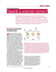
(a) Flex-OneNAND (b) WideIO (c) HMC (d) UFS (e) ONFI (f) eMMC.
5 5 7 8 10 11 12 14 15 17 26
3.2
Flex-OneNAND Memory Organization.
3.3
ONFI Memory Organization.
3.4
eMMC Memory Organization.
3.5
UFS Memory Organization.
3.6
HMC Memory Organization.
3.7
WideIO Memory Organization.
4.1
4.2
Top level of the novel common architecture includes two types of memory cores, operation modes module, cache, buffers, Serializer and Deserializer logic and a switch to change between different hosts (links) Flash memory core
4.3
Memory partitions
4.4
Main States of Flash Device
4.5
Main States of DRAM Device
33 33 34 34 34 34 37
39 53 68 70
4.6
DRAM Memory Core
71
4.7
DRAM Interface
4.8
DRAM Frame
4.9
DRAM Initialization
4.10
DRAM Operations
71 72 73 76
4.11
DRAM Power States
5.1
Reset pin asserted for 1 clock cycle and then deasserted.
5.2
Memory flash core is initialized with random data
5.3
Host starts to send read command
5.4
read command frame is completely stored in device
5.5
memory flash core is transferred successfully to the buffer
85
5.6
write command frame is completely stored in device
5.7
New data is transferred from buffer to the flash memory core successfully erase command is completely stored in the device
85 86
5.8
80 83 83 84 84
86
5.9
All stored data in the memory core is successfully erased
87
5.10
UVM Classes Hierarchy
5.11
UVM Phases Hierarchy
5.12 5.13
The Proposed Architecture of the UVM Environment for the Universal Memory Controller Architecture The Interface between the environment and the DUT
89 90 94
5.14
Wave form of the read operation
5.15
Wave form of the write operation
95 96 96
LIST OF TABLES Table No.
Name
Page
2.1
Main applications of Flash Memory
2.2
256-Mbit SDRAM device configurations Comparison between different memory controllers
9 13 31 38
3.1 4.1
Comparison between the proposed common architecture and the most famous memory controller protocols
4.2
Write Command/Response Frame
4.3
Data Write Frame
4.4
Read / Write Configuration Register
40 40 42
4.5
Read / Write Status Register
42
4.6
READ CMD/Response Frame
44
4.7
Data Read Frame
4.8
Read / Write Configuration Register
44 45
4.9
Read / Write Status Register
4.10
Erase CMD/Response frame
4.11 Erase Configuration Register
46 48 49
4.12
Erase Status Register
49
4.13
Command/ Response frame Interrupt
4.14
Standard Inquiry Data
50 51
4.15
Partition Configuration register
54
4.16
Partition Status register
54
4.17
Partition Command Frame
57
4.18
Power Command/Response Frame
59
4.19
Power Management command status register
4.20
Write Protect Command Frame
4.21
Write Protect Status Register
59 60 61
4.22
Read/Write Configuration Register
61
4.23
Background CMD Frame
62
4.24
Copyback CMD Frame
62
Chapter 1: Introduction
1
Introduction
1.1 Overview of the Problem With the move to multicore computing, the demand for memory bandwidth grows with the number of cores. It is predicted that multicore computers will need 1 TBps of memory bandwidth. However, memory device scaling is facing increasing challenges due to the limited number of read and write cycles in flash memories and capacitor-scaling limitations for DRAM cells. Therefore, memory bottleneck is one of the main challenges in modern VLSI design, [1]. Modern systems have complex memory hierarchies with diverse types of volatile and non-volatile memories such as DRAM and Flash. Microprocessors communicate with memory cores through memory controllers. It is the task of the memory controller to manage these devices. To improve this communication as a solution for the memory bottleneck, the memory cores and memory controllers can be improved. The most famous existing memory cores–based solutions are to increase the amount of on-chip memory elements. However, this solution is expensive and the most famous existing memory controllers– based solution is to improve the controller architectures and scheduling algorithms. Part of the idea behind the solution is to unload low-level memory management from the host processor, freeing up resources. The main aim of the memory controller is to provide the most suitable interface and protocol between the host and the memories to efficiently handle data, maximizing transfer speed, data integrity and information retention. Designing memory controllers is challenging in terms of performance, area, power consumption and reliability.
1.2 Goal In this thesis, novel common memory controller architecture is proposed which includes all powerful features. The feature is a command or configuration method that adds more control to the host over the device. In order to adopt the user needs, all the features are designed to be optionally enabled or disabled according to the user desire. The common architecture supports two types of memory types: FLASH and DRAM. So, the important question here is that; what is the importance to support these specific memory types? The answer is that these specific memory types have wide range of applications and their memory cell implementations give them advantages in terms of cost and size over other memory types. Dynamic random access memories (DRAM) are volatile high-density READ/WRITE devices. DRAMs require not only constant power to retain data but also that the stored data must be refreshed frequently.
1
Chapter 1: Introduction
Flash memories exhibit higher densities than DRAM because a flash memory cell consists of on transistor and does not need refreshing, whereas a DRAM cell is one transistor plus a capacitor that has to be refreshed. Typically, a flash memory consumes mush less power than an equivalent DRAM and can be used as a hard disk replacement in many applications. So it’s obvious that flash beats DRAM in terms of power consumption. But DRAM relative to other memory types (like SRAM) has low cost and size on the chip. DRAM requires only one-sixth the numbers of transistors that SRAM requires. Therefore, DRAM is considerably less expensive and needs less area than SRAM, [1]. So it is powerful for this common architecture to support the two types: FLASH and DRAM.
1.3 Structure The thesis has been divided into six chapters including this one. Chapter 1 introduces the project and motivation behind it. Chapter 2 deals with the state of the art of the essentials of the project. The third chapter presents research study on different memory controllers in the industry. Chapter 4 shows the system level of the novel memory controller and the specifications of the system. Chapter 5 presents the results and the verification methods in the project. Conclusion and future scopes are proposed in chapter 6.
2
Chapter 2: State of the art
2
State of the art
This chapter summarizes the current technologies and architectures of memory systems and memory controller proposed in the field, which are related to the topic of the thesis, it starts with an introduction on non-volatile memory technology evolution in section 2.1, In the following section 2.2 the concept of Flash memory is discussed. The DRAM memory is discussed in section 2.3. FPGA flow and FPGA architecture are discussed in section 2.4. Section 2.5 discusses the related work.
2.1 Non-Volatile Memory Technology Evolution Memories represent a significant portion of the semiconductor market and they are key components of all electronic systems. From a system view point, semiconductor memories can be divided into two major categories: the RAM’s (Random Access Memories), whose content can be changed in a short time and for a virtually unlimited number of times, and the ROM’s (Read Only Memories), whose content cannot be changed, or at least not in a time comparable with the clock period of the system. But there is another very important feature which differentiates the two families: RAM’s loose their content when the power is switch-off while ROM’s retain their content virtually for ever. The ideal memory would combine the writing properties of RAM’s with the data retention properties of ROM’s: increasing efforts have been devoted to find a viable technology for the ―universal‖ memory and some very promising candidates have been recently identified, but none of them is ready for volume production yet. So far, among the semiconductor memories that have reached the industrial maturity, the one that has got closest to the goal belongs to the category of nonvolatile memories. That category includes all the memories whose content can be changed electrically but it is retained even when the power supply is removed. Those memories are still ROM’s from a system view point because the time to change their content is too long with respect to the clock period, but they are significantly more flexible than the masked ROM’s, whose content is defined during their fabrication process and can never be changed. The history of non-volatile memories started in the early 70’s, with the introduction in the market of the first EPROM (Erasable Programmable Read Only Memory). Since then, non-volatile memories have been always considered one of the most important families of semiconductor memory. However, until mid 90’s, the relevance of this kind of memories was related more to the key role they play in most electronic systems and to the scientific interest for their memory cell concepts, than to the economical size of their
3
Chapter 2: State of the art market segment. The dramatic growth of the non-volatile memory market, which started in 1995, has been fuelled by two major events: the first was the introduction of Flash memories and the second was the development of battery-supplied electronic appliances, mainly the mobile phones but also PDA’s, MP3 players, digital still cameras and so on. Almost in every electronic system, some pieces of information must be stored in a permanent way, i.e. they must be retained even when the system is not powered. Program codes for microcontrollers are probably the most popular example: any system based on microcontrollers needs the permanent storage of the set of instructions to be executed by the processors to perform the different tasks required for a specific application. A similar example is given by the parameters for DSP’s (Digital Signal Processors); those also are pieces of information to be stored in a non-volatile memory. In general, any programmable system requires a set of instructions to work; those instructions, often called ―the firmware‖, cannot be lost when the power supply is switched off. But solid state non-volatile memories are widely used not only for the firmware. In most systems there are data which are set either by the system manufacturer, or by the distributors, or by the end users, and those data must be retained at power-off. The examples are many and for a variety of different functions: identification and security codes, trimming of analog functions, setting of system parameters, system self-diagnostic, end-user programmable options and data, insystem data acquisition and many others. Due to their pervasiveness, non-volatile memories have penetrated all electronic market segments: industrial, consumer, telecommunication, automotive and computer peripherals. Even in personal computers, that host a magnetic memory media (the hard disk) for mass storage and RAM’s as working memory, there are solid state non-volatile memories: the system boot, which tells the system what to do at power-up, before the operating system is downloaded from the hard disk into the RAM, is stored in a non-volatile memory. Moreover, in the hard disk drive itself, which is a microcontroller based system, there is a non-volatile memory. To cover such a variety of application needs, non-volatile memories are available in a wide range of capacities, from few Kbits to hundreds of Mbits, and with a number of different product specifications. Moreover, thanks to the evolution of integration technology, non-volatile memories can also be embedded into the processor chip; today a significant portion of them, mainly in the small and medium size range, is not sold as stand-alone memory but integrated with other logic functions. This trend, initiated by microcontrollers, has been extended to a wider range of products and to higher complexity towards the integration of complete systems in a single chip (SoC’s: System-on-a-Chip); non-volatile memory has been an enabling technology for this evolution to happen and smart cards are just an example of a popular single chip electronic systems that could not exist without that kind of technology.
4
Chapter 2: State of the art
Cost EEPROM Flash EPROM ROM
Byte rewrite capability Programmable and erasable in system
Programmable, not electrically erasable
Not electrically programmable Flexibility
Fig. 2.1 Comparison of non-volatile memories.
35 30
Market(B$)
25 20
DRAM Flash
15
SRAM
10 5 0 1996 1997 1998 1999 2000 2001 2002 2003 2004 2005 2006 2007
Fig. 2.2 Semiconductor Memory Market
Moreover the development of multimedia applications and the convergence of personal consumer appliances towards portable systems that manage data, communication, images and music, is dramatically increasing the demand for a friendly way of storing and moving large files: memory cards, in different formats, are the rising segment that is further fuelling the growth of Flash memory market. Indeed, the dramatic increase of flash memory has been the most relevant event in the semiconductor memory market in the last decade (Fig. 2.2). Among the many different Flash technologies that have been conceived and the less that have been developed to volume production, we can identify two dominant ones: NOR Flash, which is the mainstream technology for the applications that requires the storage of codes and parameters, and more generally for embedded memories (system-embedded and chip-embedded) that has to provide random memory access.
5
Chapter 2: State of the art NAND Flash, which provide only serial access, but higher density and lower cost than NOR, and it is therefore the dominant technology for data storage and memory cards [2].
2.2 Flash Memory Systems This section gives an overview of types of flash memory, starting from NOR Flash memory type, NAND flash memory type and the applications related to the 2 types.
2.2.1 NOR Flash Memory NOR Flash memory was born in mid 80’s and it was introduced at the end of that decade as EPROM replacement. The first generation products were actually looking like erasable EPROM’s, because they required an external 12 V supply for program and erase, they only offered a bulk erase capability (all memory content erased at once) and they required the time-consuming erase procedure to be managed by an external machine (programmer or system microcontroller). In mid 90’s, there was a second generation of NOR Flash memory; those new products stated to be significantly different from EPROM, mainly in the direction of being more flexible a and better suited for in-system reprogramming. The most important new features offered by second generation Flash memories were:
Single power supply: the high programming voltage was generated on-chip by a charge pump from the standard 5 V or 3 V external power supply, removing the quite troublesome requirement of a second power line on the application board. Sector erase: the memory array was divided in sectors, of equal (64 KB) or different sizes (8 KB 64 KB), to allow the modification of a portion of the memory while keeping the information stored in the rest of it. Embedded algorithms: a state machine was provided on-chip to run the erase algorithms locally, without keeping the system busy for all the time needed to complete the operation.
The explosion of mobile phone market, which has really been the killer application for Flash memory, has pushed the development of a third generation of products, specifically designed for that application, whose main new features are:
Very low power supply voltage (1.8 V), to minimize power consumption both in reading and writing. Different power supply pins, one for programming voltage, one for the chip main supply voltage and one for input/output circuitry, to allow the maximum flexibility for power management at system level. Different memory banks, to allow reading one portion of the memory while writing another one (read-while-write feature). Fast read modes (burst and page) to enhance the data throughput between the processor and the memory, which the bottleneck for system performance.
6
Chapter 2: State of the art Indeed, the advanced architecture of latest generation NOR Flash memory is effectively conceived to meet the requirements of mobile phones: it optimizes the trade-off between speed and power consumption, and it gives the possibility of using a single chip to store both code and data, through the read-while-write feature. NOR Flash memories are all but commodities: they are available in a variety of densities (from 1Mbit to 512 Mbit), of voltages (from 1.8 V to 5 V and with single or triple voltage supply), of read parallelism (serial or random x8, x16 and x32, burst or page access), of memory partitioning (bulk erase or sector erase, equal sectors or boot block sector scheme, single bank, dual banks or multiple banks). All the different product specifications are meant to fit the different needs of specific applications. The variety of products is the best demonstration of the versatility of NOR Flash technology, which together with its excellent cost/performance trade-off and its superior reliability have been key success factors of this technology. All the nice features of NOR Flash products are inherently related to the memory cell concept and the memory array organization (Fig. 2.3). The memory cells are arranged in a NOR type array organization, which means that all the cells are parallel connected with a common ground node and the bit lines are directly connected to the drains of memory cells[2].
Fig. 2.3 Difference Between NOR and NAND Flash Memory
7
Chapter 2: State of the art
2.2.2 NAND Flash Memory NAND Flash has basically the same memory cell structure as NOR, but it has a totally different array organization (Fig. 2.3) and it employs a different programming mechanism. The memory array is organized in NAND arrangement, i.e. a number (16 or 32) of cells are connected in series between ground and the bit line contact. That allows increasing the density vs. NOR, which instead requires a ground line and a bit line contact every two cells, but it dramatically affects speed. In fact every cell must be read through a number (15 or 31) other cells, strongly reducing read current; that results in much longer access time (microseconds compared with the tens of nanoseconds of NOR) and it practically prevents the usage of this technology for random access memories and restricts it to serial memories only. Moreover, the read-through mechanism make this memory type much more noise and pattern sensitive than NOR; therefore, implementing multilevel storage in NAND Flash more difficult and, although two-bit-per-cell products are available now, the mainstream for NAND is still one-bit-per-cell. The higher density and the higher programming throughput make NAND the dominant Flash technology for memory cards; as the data storage is the fastest growing application for flash memories, the portion of market served by NAND technology is increasing. This technology is believed to face the same scaling issues than NOR; still the effort to push it down to 45 nm and beyond will be maintained, unless an alternative technology will show better cost/performance combination[2].
30 25
Market(B$)
20 NAND 15
NOR
10 5 0 2002
2003
2004
2005
2006
Fig. 2.4 Flash Memory Market Sharing by technology
2007
8
Chapter 2: State of the art
Function
Application
Data
Cameras
MP3 NAND
Code + Data
DVD Mobile
Networking
STB
Code + parameter
Industrial NOR PC
Code Only
Modem
Automotive Printer, Games, TV
Table 2.1 Main applications of Flash Memory
2.3 DRAM Memory This section gives an overview of DRAM memory system. Starting from the DRAM basics in section 2.3.1. The DRAM device configuration is discussed in section 2.3.2. Burst length for data In/Out DRAM is discussed in section 2.3.3. DRAM memory system organization is discussed in section 2.3.4.
2.3.1 DRAM Basics A random-access memory (RAM) that uses a single transistor-capacitor pair for each bit is called a dynamic randomaccess memory or DRAM. Figure 5 shows, in the bottom right corner, the circuit for the storage cell in a DRAM. This circuit is dynamic because the capacitors storing electrons are not perfect devices, and their eventual leakage requires that, to retain information stored there, each capacitor in the DRAM must be periodically refreshed (i.e., read and rewritten). Each DRAM die contains one or more memory arrays, rectangular grids of storage cells with each cell holding one bit of data. Because the arrays are rectangular grids, it is useful to think of them in terms associated with typical grid-like structures. Memory arrays are organized to rows and columns.
9
Chapter 2: State of the art
Column decoder Data In/Out buffers
Sense Amplifier
Row Decoder
...Columns….
Memory
Array
Fig. 2.5 Basic organization of DRAM internals
A DRAM chip’s memory array with the rows and columns indicated is pictured in Figure 2.5. By identifying the intersection of a row and a column (by specifying a row address and a column address to the DRAM), a memory controller can access an individual storage cell inside a DRAM chip so as to read or write the data held there. One way to characterize DRAMs is by the number of memory arrays inside them. Memory arrays within a memory chip can work in several different ways. They can act in unison, they can act completely independently, or they can act in a manner that is somewhere in between the other two. If the memory arrays are designed to act in unison, they operate as a unit, and the memory chip typically transmits or receives a number of bits equal to the number of arrays each time the memory controller accesses the DRAM. For example, in a simple organization, a x4 DRAM (pronounced ―by four‖) indicates that the DRAM has at least four memory arrays and that a column width is 4 bits (each column read or write transmits 4 bits of data). In a x4 DRAM part, four arrays each read 1 data bit in unison, and the part sends out 4 bits of data each time the memory controller makes a column read request. Likewise, a x8 DRAM indicates that the DRAM has at least eight memory arrays and that a column width is 8 bits. Figure 2.6 illustrates the internal organization of x2, x4, and x8 DRAMs. In the past two decades, wider output DRAMs have appeared, and x16 and x32 parts are now common, used primarily in high-performance applications. Note that each of the DRAM illustrations in Figure 6 represents multiple arrays but a single bank. Each set of memory arrays that operates independently of other sets is referred to as a bank, not an array. Each bank is independent in that, with only a few restrictions, it can be activated, precharged, read out, etc. at the same time that other banks (on the same DRAM device or on other DRAM devices) are being activated, precharged, etc. The use of multiple independent banks of memory has been a common practice in computer design since DRAMs were invented. In particular, interleaving multiple memory banks has been a popular method used to achieve highbandwidth memory busses using low-bandwidth devices [3].
10
Chapter 2: State of the art
Fig. 2.6 logical organization of wide data out DRAMS.
2.3.2 DRAM Device Configuration Modern DRAM devices are controlled by state machines whose behavior depends on the input values of the command signals as well as the values contained in the programmable mode register in the control logic. Figure 2.7 shows that in an SDRAM device, the mode register contains three fields: CAS latency, burst type, and burst length. Depending on the value of the CAS latency field in the mode register, the DRAM device returns data two or three cycles after the assertion of the column read command. The value of the burst type determines the ordering of how the SDRAM device returns data, and the burst length field determines the number of columns that an SDRAM device will return to the memory controller with a single column read command. SDRAM devices can be programmed to return 1, 2, 4, or 8 columns or an entire row. D-RDRAM devices and DDRx SDRAM devices contain more mode registers that control an ever larger set of programmable operations, including, but not limited to, different operating modes for power conservation, electrical termination calibration modes, self-test modes, and write recovery duration [3].
11
Chapter 2: State of the art
CKE CLK
Mode register
2 1
0
Control logic
WE# CAS# RAS#
Command decoder
CS#
CAS latency
Burst length
Burst type
Mode register
Addr bus
Address register
Fig. 2.7 Programmable Mode Register in an SDRAM device.
DRAM devices are classified by the number of data bits in each device, and that number typically quadruples from generation to generation. For example, 64-Kbit DRAM devices were followed by 256-Kbit DRAM devices, and 256Kbit devices were, in turn, followed by 1-Mbit DRAM devices. Recently, half- generation devices that simply double the number of data bits of previous-generation devices have been used to facilitate smoother transitions between different generations. As a result, 512-Mbit devices now exist alongside 256-Mbit and 1 Gbit devices. In a given generation, a DRAM device may be configured with different data bus widths for use in different applications. Table 2.2 shows three different configurations of a 256-Mbit device. The table shows that a 256-Mbit SDRAM device may be configured with a 4-bit-wide data bus, an 8-bit-wide data bus, or a 16-bit-wide data bus. In the configuration with a 4-bit-wide data bus, an address provided to the SDRAM device to fetch a single column of data will receive 4 bits of data, and there are 64 million separately addressable locations in the device with the 4-bit data bus. The 256-Mbit SDRAM device with the 4-bit-wide data bus is thus referred to as the 64 Meg x4 device. Internally, the 64 Meg x4 device consists of 4 bits of data per column, 2048 columns of data per row, and 8192 rows per bank, and there are 4 banks in the device. Alternatively, a 256-Mbit SDRAM device with a 16-bit-wide data bus will have 16 bits of data per column, 512 columns per row, and 8192 rows per bank; there are 4 banks in the 16 Mbit, x16 device. In a typical application, 4 16 Mbit, x16 devices can be connected in parallel to form a single rank of memory with a 64-bit-wide data bus and 128 MB of storage. Alternatively, 16 64 Mbit, x4 devices can be connected in parallel to form a single rank of memory with a 64-bit-wide data bus and 512 MB of storage.
12
Chapter 2: State of the art Table 2.2
256-Mbit SDRAM device configurations
Device configuration
64 Meg × 4
32 Meg × 8
16 Meg × 16
Number of banks
4
4
4
Number of rows
8192
8192
8192
Number of columns
2048
1024
512
Data bus width
4
8
16
In the 256-Mbit SDRAM device, the size of the row does not change in different configurations, and the number of columns per row simply decreases with wider data busses specifying a larger number of bits per column. However, the constant row size between different configurations of DRAM devices within the same DRAM device generation is not a generalized trend that can be extended to different device generations. For example, In 1-Gbit DDR2 SDRAM devices, there are eight banks of DRAM arrays per device. In the x4 and x8 configuration of the 1-Gbit DDR2 SDRAM device, there are 16,384 rows per bank, and each row consists of 8192 bits. In the x16 configuration, there are 8192 rows, and each row consists of 16,384 bits. These different configurations lead to different numbers of bits per bitline, different numbers of bits per row activation, and different number of bits per column access. In turn, differences in the number of bits moved per command lead to different power consumption and performance characteristics for different configurations of the same device generation. For example, the 1-Gbit, x16 DDR2 SDRAM device is configured with 16,384 bits per row, and each time a row is activated, 16,384 DRAM cells are simultaneously discharged onto respective bitlines, sensed, amplifyed, and then restored. The larger row size means that a 1-Gbit, x16 DDR2 SDRAM device with 16,384 bits per row consumes significantly more current per row activation than the x4 and x8 configurations for the 1-Gbit DDR2 SDRAM device with 8192 bits per row. timing parameters designed to limit peak power dissipation characteristics of DRAM devices.
2.3.3 Burst length For Data I/O DRAM In SDRAM and DDRx SDRAM devices, a column read command moves a variable number of columns. , an SDRAM device can be programmed to return 1, 2, 4, or 8 columns of data as a single burst that takes 1, 2, 4, or 8 cycles to complete. In contrast, a D-RDRAM device returns a single column of data with an 8 beat12 burst. Figure 8.20 shows an 8 beat, 8 column read data burst from an SDRAM device and an 8 beat, single column read data burst from a D-RDRAM device. The distinction between the 8 column burst of an SDRAM device and the single column data burst of the D-RDRAM device is that each column of the SDRAM device is individually addressable, and given a column address in the middle of an 8 column burst, the SDRAM device will reorder the burst to provide the data of the requested address first. This capability is known as critical-word forwarding. For example, in an SDRAM device programmed to provide a burst of 8 columns, a column read command with a column address of 17 will result in the data burst of 8 columns of data with the address sequence of 17-18-19-20-21- 22-23-16 or 17-16-19-18-21-20-23-22, depending on the burst type as defined in the programmable register. In contrast, each column of a D-RDRAM device consists of 128 bits of data, and each column access command moves 128 bits of data in a burst of 8 contiguous beats in strict burst ordering. An D-RDRAM device supports neither programmable burst lengths nor different burst ordering.
13
Chapter 2: State of the art
2.3.4 DRAM Memory System Organization This section focuses on the organization of DRAM devices in the context of multi-device memory systems. The organization of multiple DRAM devices into a memory system can impact the performance of the memory system in terms of system storage capacity, operating data rates, access latency, and sustainable bandwidth characteristics. It is therefore of great importance that the organization of multiple DRAM devices into larger memory systems be examined in detail. However, the absence of commonly accepted nomenclature has hindered the examination of DRAM memory-system organizations. Without a common basis of well-defined nomenclature, technical articles and data sheets sometimes succeed in introducing confusion rather than clarity into discussions on DRAM memory systems. In one example, a technical data sheet for a system controller used the word bank in two bulleted items on the same page to mean two different things. In this data sheet, one bulleted item proclaimed that the system controller could support 6 banks (of DRAM devices). Then, several bulleted items later, the same data sheet stated that the same system controller could support SDRAM devices with 4 banks. In a second example, an article in a well respected technical journal examined the then-new i875P system controller from Intel and proceeded to discuss the performance advantage of the system controller due to the fact that the i875P system controller could control 2 banks of DRAM devices (it can control two entire channels). In these two examples, the word bank was used to mean three different things. While the meaning of the word bank can be inferred from the context in each case, the overloading and repeated use of the word introduces unnecessary confusion into discussions about DRAM memory systems. In this section, the usage of channel, rank, bank, row, and column is defined, and discussions in this will conform to the usage in this section.
2.3.4.1 Channel In contrast to system controllers that use a single DRAM memory controller to control the entire memory system, Figure 2.8 shows that the Alpha EV7 processor and the Intel i925x system controller each have two DRAM controllers that independently control 64-bit-wide data busses. The use of independent DRAM memory controllers can lead to higher sustainable bandwidth characteristics, since the narrower channels lead to longer data bursts per cacheline request, and the various inefficiencies dictated by DRAM-access protocols can be better amortized. As a result, newer system controllers are often designed with multiple memory controllers despite the additional die cost.
64 DMC System controller Intel DMC i925X
DDR2 64 DDR2
Fig. 2.8 System With 2 logical channels.
2.3.4.2 Rank Figure 2.9 shows a memory system populated with 2 ranks of DRAM devices. Essentially, a rank of memory is a “bank” of one or more DRAM devices that operate in lockstep in response to a given command. However, the word bank has already been used to describe the number of independent DRAM arrays within a DRAM device. To lessen the confusion associated with overloading the nomenclature, the word rank is now used to denote a set of DRAM
14
Chapter 2: State of the art devices that operate in lockstep to respond to a given command in a memory system. Figure 2.9 illustrates a configuration of 2 ranks of DRAM devices in a classical DRAM memory system topology. In the classical DRAM memory system topology, address and command busses are connected to every DRAM device in the memory system, but the wide data bus is partitioned and connected to different DRAM devices. The memory controller in this classical system topology then uses chip select signals to select the appropriate rank of DRAM devices to respond to a given command. In modern memory systems, multiple DRAM devices are commonly grouped together to provide the data bus width and capacity required by a given memory system. For example, 18 DRAM devices, each with a 4bit-wide data bus, are needed in a given rank of memory to form a 72-bit-wide data bus. In contrast, embedded systems that do not require as much capacity or data bus width typically use fewer devices in each rank of memory sometimes as few as one device per rank. Rank 0 Data bus 16 bit
Rank 1
Bank 0
Bank 0
Bank 1
Bank 1
Bank 2
Bank 2
Bank 3
Bank 2
DMC
Chip select 0 Chip select 1 Fig. 2.9 Memory systems with 2 Ranks devices.
2.3.4.3 Bank As described previously, the word bank had been used to describe a set of independent memory arrays inside of a DRAM device, a set of DRAM devices that collectively act in response to commands, and different physical channels of memory. In this section, the word bank is only used to denote a set of independent memory arrays inside a DRAM device. Figure 2.9 shows an SDRAM device with 4 banks of DRAM arrays. Modern DRAM devices contain multiple banks so that multiple, independent accesses to different DRAM arrays can occur in parallel. In this design, each bank of memory is an independent array that can be in different phases of a row access cycle. Some common resources, such as I/O gating that allows access to the data pins, must be shared between different banks. However, the multi-bank architecture allows commands such as read requests to different banks to be pipelined.
15
Chapter 2: State of the art Certain commands, such as refresh commands, can also be engaged in multiple banks in parallel. In this manner, multiple banks can operate independently or concurrently depending on the command. For example, multiple banks within a given DRAM device can be activated independently from each other—subject to the power constraints of the DRAM device that may specify how closely such activations can occur in a given period of time. Multiple banks in a given DRAM device can also be precharged or refreshed in parallel, depending on the design of the DRAM device.
2.3.4.4 Row In DRAM devices, a row is simply a group of storage cells that are activated in parallel in response to a row activation command. In DRAM memory systems that utilize the conventional system topology such as SDRAM, DDR SDRAM, and DDR2 SDRAM memory systems, multiple DRAM devices are typically connected in parallel in a given rank of memory. DRAM devices can be connected in parallel to form a rank of memory. The effect of DRAM devices connected as ranks of DRAM devices that operate in lockstep is that a row activation command will activate the same addressed row in all DRAM devices in a given rank of memory. This arrangement means that the size of a row—from the perspective of the memory controller—is simply the size of a row in a given DRAM device multiplied by the number of DRAM devices in a given rank, and a DRAM row spans across the multiple DRAM devices of a given rank of memory. A row is also referred to as a DRAM page, since a row activation command in essence caches a page of memory at the sense amplifiers until a subsequent precharge command is issued by the DRAM memory controller. Various schemes have been proposed to take advantage of locality at the DRAM page level. However, one problem with the exploitation of locality at the DRAM page level is that the size of the DRAM page depends on the configuration of the DRAM device and memory modules, rather than the architectural page size of the processor.
2.3.4.5 Column In DRAM memory systems, a column of data is the smallest addressable unit of memory. The size of a column of data is the same as the width of the data bus. In a Direct RDRAM device, a column is defined as 16 bytes of data, and each read command fetches a single column of data 16 bytes in length from each physical channel of Direct RDRAM devices. A beat is simply a data transition on the data bus. In SDRAM memory systems, there is one data transition per clock cycle, so one beat of data is transferred per clock cycle. In DDRx SDRAM memory systems, two data transfers can occur in each clock cycle, so two beats of data are transferred in a single clock cycle. The use of the beat terminology avoids overloading the word cycle in DDRx SDRAM devices. In DDRx SDRAM memory systems, each column access command fetches multiple columns of data depending on the programmed burst length. For example, in a DDR2 DRAM device, each memory read command returns a minimum of 4 columns of data. The distinction between a DDR2 device returning a minimum burst length of 4 beats of data and a Direct RDRAM device returning a single column of data over 8 beats is that the DDR2 device accepts the address of a specific column and returns the requested columns in different orders depending on the programmed behavior of the DRAM device. In this manner, each column is separately addressable. In contrast, Direct RDRAM devices do not reorder data within a given burst, and a 16-byte burst from a single channel of Direct RDRAM devices is transmitted in order and treated as a single column of data.
16
Chapter 2: State of the art
2.4 FPGA and FPGA Architecture
FPGA or Field Programmable Gate Arrays can be programmed or configured by the user or designer after manufacturing and during implementation. Hence they are otherwise known as On-Site programmable. Unlike a Programmable Array Logic (PAL) or other programmable device, their structure is similar to that of a gate-array or an ASIC. Thus, they are used to rapidly prototype ASICs, or as a substitute for places where an ASIC will eventually be used. This is done when it is important to get the design to the market first. Later on, when the ASIC is produced in bulk to reduce the NRE cost, it can replace the FPGA. The programming of the FPGA is done using a logic circuit diagram or a source code using a Hardware Description Language (HDL) to specify how the chip should work. FPGAs have programmable logic components called ‚logic blocks, and a hierarchy or reconfigurable interconnects which facilitate the ‚wiring‛ of the blocks together. The programmable logic blocks are referred to as configurable logic blocks and reconfigurable interconnects are referred to as switch boxes. CLBs can be programmed to perform complex combinational functions, or simple logic gates. In most FPGAs the logic blocks also include memory elements, which can be as simple as flip-flops, or as complex as complete blocks of memory.
2.4.1 FPGA Design Flow The flow for the design using FPGA outlines the whole process of device design, and guarantees that none of the steps is overlooked. Thus, it ensures that we have the best chance of getting back a working prototype that will correctly function in the final system to be designed.
17
Chapter 2: State of the art
HDL coding of Design
Verification functionality
Synthesis
Translate
Mapping
Place and Route
Program the FPGA Fig. 2.10 FPGA Design Flow
2.4.2 Behavioral Simulation After HDL designing, the code is simulated and its functionality is verified using simulation software, e.g. Xilinx ISE or Questasim simulator. The code is simulated and the output is tested for the various inputs. If the output values are consistent with the expected values then we proceed further else necessary corrections are made in the code. This is what is known as Behavioral Simulation. Simulation is a continuous process. Small sections of the design should be simulated and verified for functionality before assembling them into a large design. After several iterations of design and simulation the correct functionality is achieved. Once the design and simulation is done then another design review by some other people is done so that nothing is missed and no improper assumption made as far as the output functionality is concerned.
18
Chapter 2: State of the art
2.4.3 Synthesis of Design Post the behavioral simulation the design is synthesized. During simulation following takes place: (i) HDL Compilation The Xilinx ISE tool compiles all the sub-modules of the main module. If any problem takes place then the syntax of the code must be checked. (ii) HDL synthesis Hardware components like Multiplexers, Adders, Subtractors, Counters, Registers, Latches, Comparators, XORs, Tri-State buffers, Decoders are synthesized from the HDL code.
2.4.4 Advantages of FPGA FPGAs have become very popular in the recent years owing to the following advantages that they offer: Fast prototyping and turn-around time- Prototyping is the defined as the building of an actual circuit to a theoretical design to verify for its working, and to provide a physical platform for debugging the core if it doesn’t. Turnaround is the total time between expired between the submission of a process and its completion. On FPGAs interconnects are already present and the designer only needs to fuse these programmable interconnects to get the desired output logic. This reduces the time taken as compared to ASICs or full-custom design. NRE cost is zero- Non-Recurring Engineering refers to the one-time cost of researching, developing, designing and testing a new product. Since FPGAs are reprogrammable and they can be used without any loss of quality every time, the NRE cost is not present. This significantly reduces the initial cost of manufacturing the ICs since the program can be implemented and tested on FPGAs free of cost. High-Speed- Since FPGA technology is primarily based on referring to the look-up tables the time taken to execute is much less compared to ASIC technology. Low cost- FPGA is quite affordable and hence is very designer-friendly. Also the power requirement is much less as the architecture of FPGAs is based upon LUTs.
19
Chapter 2: State of the art
2.5 Related Work Chapter 3 describes different types of most famous memory controllers in the industry. Comparing this work with the described memory controllers, then this work is a novel work. This thesis proposes a novel universal memory controller includes the most major and important features for any manufacturer and this architecture combine the advantages of most widely known protocols on the scene. These specifications covered the most important types of memory; Flash and DRAM in one device. This novel architecture has extremely simple design which can utilize in many applications. The suggested solution is shown with an implementation in Verilog language and verified by the latest technology in verification which is UVM methodology. In contrast the work for this thesis focuses on building the system level of the novel design, Implementation and verification of memory controller at RTL level, which allows synthesis of the design.
20
Chapter 3: Research Study on Different Memory Controllers
3
Research Study on Different Memory controllers
This chapter clarifies the differences between six memory architectures, which are Flex-OneNAND, Open NAND Flash Memory (ONFI), Embedded Multi-Media Card (eMMC), Hybrid Memory Cube (HMC), WideIO, and Universal Flash Storage (UFS). The chapter shows the impact of such discriminating differences on choosing the most suitable architecture for certain application. The comparison is done in terms of most important features to microelectronics industry point of view. The comparison shows that the highest speed gives by HMC v.1.0 which reaches 15GBps supported with power management per link, Flex-OneNAND provides single flash chip with ultrahigh density of NAND and simplified interface of NOR with the simplest architecture at very attractive price points, WideIO offers more bandwidth at lower power. Regarding the lowest power consumption, eMMC is sparkling. UFS combining the speed of SSD with the slim form factor and low power of eMMC. ONFI supports increased performance through parallelism made possible by multiple Logic Units and interleaved addressing. This comparison is very powerful for designers to decide which memory controller is suitable for their applications and satisfies their requirements.
3.1 Introduction With the move to multicore computing, the demand for memory bandwidth grows with the number of cores. It is predicted that multicore computers will need 1 TBps of memory bandwidth. However, memory device scaling is facing increasing challenges due to the limited number of read and write cycles in flash memories and capacitorscaling limitations for DRAM cells. Therefore, memory bottleneck is one of the main challenges in modern VLSI design, [4]. Modern systems have complex memory hierarchies with diverse types of volatile and non-volatile memories such as DRAM and Flash. Microprocessors communicate with memory cores through memory controllers. It is the task of the memory controller to manage these devices. To improve this communication as a solution for the memory bottleneck, the memory cores and memory controllers can be improved. The most famous existing memory cores– based solutions are to increase the amount of on-chip memory elements. However, this solution is expensive and the most famous existing memory controllers–based solution is to improve the controller architectures and scheduling algorithms, [5]. Part of the idea behind the solution is to unload low-level memory management from the host processor, freeing up resources. The main aim of the memory controller is to provide the most suitable interface and protocol between the host and the memories to efficiently handle data, maximizing transfer speed, data integrity and information retention. Designing memory controllers is challenging in terms of performance, area, power consumption and reliability.
21
Chapter 3: Research Study on Different Memory Controllers There is a great variety of interfaces and protocols, which provide access to the internal memory cores in different ways to read, write or erase. Examples of Flash-based memory controllers are Flex-OneNAND, ONFI, eMMC and UFS. For DRAM based memory controllers, HMC and WideIO are the two famous examples. Flex-OneNAND incorporates SLC and MLC NAND on a single piece of silicon, allowing application designers to choose the portion of SLC and MLC NAND storage to be used in any particular design through a simple adjustment to the accompanying software. This maximizes the performance and efficiency of the embedded flash chip. The lack of a standard caused serious design problems like host systems had to accommodate differences between vendors’ devices and adapt to generational changes in parts from a single vendor. All of this made incorporating new or updated NAND Flash components extremely costly, often requiring extensive hardware, firmware, and/or software changes and additional testing which slowed time to market. ONFI works to solve all these issues by standardizing the NAND Flash interface reducing vendor and generational incompatibilities and accelerating the adoption of new NAND products. eMMC refers to a package consisting of both flash memory and flash memory controller integrated on the same silicon die. The eMMC solution consists of 3 components; the MMC (multimedia card) interface, the flash memory and the flash memory controller; and is offered in the industry-standard BGA package. eMMC has improved some features such as secure erase and trim and high-priority interrupt to meet the demand for high performance and security. It also was created to improve data rates and throughputs for high-density chips designed to store highresolution videos. UFS is most advanced specification for embedded and removable flash memory-based storage because it includes the feature set of eMMC specification as a subset. It also references several other standards specifications by MIPI (MPHY and UniPro specifications) and INCITS T10 (SBC, SPC and SAM specifications) organizations. The UFS interface is a universal serial communication bus, based on MIPI M-PHY standard as physical layer for optimized performance and power and references the INCITS T10 SAM model for ease of adoption. HMC is a revolutionary innovation in DRAM memory architecture that sets a new standard for memory performance, power consumption and cost. HMC Combines high-speed logic process technology with a stack of through-silicon-via (TSV) bonded memory die. WideIO is stacking chips with through silicon via (TSV) interconnects with a system on chip (SoC) and improves bandwidth, latency, power, weight, and form factor. It offers twice bandwidth of LPDDR2 at the same rate of power consumption. In any memory controller, there are two sides one for card another for host; here we are focusing on card side. In this chapter, six different memory controller architectures are analyzed. Qualitative and quantitative comparison is also provided. The rest of chapter is organized as follows. In Section 3.2, the different memory architectures are presented. In Section 3.3, the fundamental differences between these six protocols are analyzed. Conclusions are given in section 3.4.
22
Chapter 3: Research Study on Different Memory Controllers
3.2 MEMORY CORES ARCHITECTURES In this section, Flex-OneNAND, ONFI, eMMC, UFS, HMC, and WideIO controller architectures are discussed and the general architecture is provided. Flex-OneNAND Flex-OneNAND is NAND Flash memory array using a NOR flash interface, with high speed host interface, it integrates on-chip a convertible (SLC and MLC) NAND Flash Array memory with two independent data buffers, boot RAM buffer, a page buffer for flash array and a one-time-programmable block (OTP). The milestone product features are synchronous/asynchronous read, super load (for synch. Read mode only); it is used to read multiple pages, synchronous/ asynchronous write, cache program; it is used to enhance the performance of program operation, copy-back program; it is used to load data into data buffer and modify it then program the modified data into designated page, erase; it is allowed to erase one block at a time, interleaving cache, interleaving erase and interleaving program. The interleaving as a concept here is to enable the host to perform operation on a chip while doing another operation on another chip. Flex-OneNAND also provides multiple sectors read operations, write protection, data protection during power down, erase suspend/ resume, handling any urgent operation which interrupts the erase operation. The Flex-OneNAND Top level Architecture as shown in Fig. 3.1 (a), [6]. ONFI ONFI stands for Open NAND Flash Interface. Early NAND Flash devices from different manufacturers use similar interface but an open standard did not exist. As a result, subtle differences exist among devices from different vendors. ONFI standard aims to provide a common standard, so different device can be used interchangeably and sets the stage for future standard NAND Flash development as shown in Fig. 3.1 (e). One of the most effective features in ONFI is Multiple Logic Unit (LUN) operations, read page can issued to one LUN while a page program is ongoing within a second LUN due to independent data buses. ONFI distinguish itself with Copy back feature which can read data from certain location in a page then transfer it to another page. Set feature; Modify settings of certain feature in parameter pages. Page cache program; cache register allows NAND to read the next page from the array while transferring the current page to host. Interleaved Operations feature may be used to complete the same operation on additional blocks on a per logical unit basis to enhance performance, there are two types of interleaving, one is concurrent interleaving array operations for all blocks start after final command and execute in parallel, and the other Overlapped Interleaving array operations are independent and start after the operation issued, [7]. eMMC The eMMC is a managed memory capable of storing code and data. It is specifically designed for mobile devices. The eMMC is intended to offer the performance and features required by mobile devices while maintaining low power consumption. It also saves power through power saving sleep mode. The eMMC device provides high speed interface timing mode of up to 200MB/s at 200MHz single data rate bus (SDR). It also supports dual data rate operating mode (DDR). It can select between SDR and DDR operation modes by setting specific bits in specific registers. The eMMC device contains features that support high throughput for large data transfer and performance for small random data more commonly found in code usage. It also contains many security features. These security appear in removing data from the memory address range using secure erase or secure trim and also appear in protecting the stored data against write or erase using write protect management by its permanent ,power-on and temporary protection types .eMMC can be locked by using password protection feature .CPU can’t access data on
23
Chapter 3: Research Study on Different Memory Controllers the locked eMMC . In eMMC device all commands are protected by CRC bits and the command is not executed if CRC check fails. eMMC communication is based on an advanced 10-signal bus shown in Fig. 3.1 (f). eMMC distinguishes itself by its maintenance background operations which reduce latencies during time critical operations like read and write. Background operations and high priority interrupt (HPI) help in executing commands with priority in order to solve NAND flash’s problems for simultaneous read and write. This feature is specifically designed for smartphones. Also to reduce overheads, read and write commands can be packed in groups of commands called packed commands which transfer in one transfer on the bus. Finally to reduce access time for both write and read, a volatile temporary storage space in eMMC is provided called Cache which can greatly reduce the latency between data transactions to improve performance. eMMC provides a far smoother transition than UFS for mainstream device platforms in terms of system compatibility. As UFS parts won’t be as cost competitive as eMMC given their high manufacturing expense. As for additional features, discard can help the host define invalid blocks of memory. Sanitize can completely erase the physical blocks where the data is stored to avoid information outflow even after deleting personal data. Data tag can tag storage data according to access and hit frequency which enhance the system's process efficiency. With power off notification, the host controller will inform the eMMC controller chip when devices are about to suffer a power outage; So that the controller chip can respond in advance before the outage. Finally with Context ID which groups different memory transactions under a single ID so the device can understand that they are related, [8]. UFS The UFS Top level Architecture as shown in Fig. 3.1 (d), Consists of 4 layers, first layer is called application layer; it consists of UFS command set layer (UCS) which handles normal commands, device manager; it has two jobs, Device level operations such as sleep, power-down management … etc. and device level configurations such as set of descriptors, handling query request… etc. Task manager handles command queue control. Second layer is UCS; it establishes the method of data exchange between host and device, it also provides device management capability. Third layer is UFS transport protocol layer (UTP), this layer services the higher layers, and its mission is to encapsulate the protocol into appropriate frame structure for the lower layer which called UFS Interconnect layer (UIC), the design features of UTP is to provide flexible architecture, so when host requests, the device controls the suitable pacing and state transitions, so we can easily deduce that UFS is an agnostic protocol. UFS is strictly use the Client-Server model, the procedure call supplied by application client on initiator is serviced by server (device) and returns the outputs and procedure call status. The lower layer is UIC; it handles the connection between UFS host and UFS device, and consists of MIPI UniPro; which provides basic transfer capabilities to UTP, and MIPI M-PHY; which is physical layer of UFS, [9]. UFS v1.1 is compatible with eMMC v4.51 command protocol improvements such as Context ID and Data Tag Additionally, many powerful features are added to UFS furthermore eMMC. Command queue is an important feature which executes high priority commands and leaves the remaining queues as lower priority. HMC HMC uses 3D single packaging of 4 or 8 DRAM memory dies and one logic die collected together using throughsilicon vias (TSV) and micro-bumps with smaller physical footprints. HMC exponentially is more power efficiency and energy savings, utilizing 70% less energy per bit than DDR3 DRAM technology. A single HMC can provide more than 15x the performance of DDR3 module which increased bandwidth. HMC reduced latency with lower queue delays and higher bank availability.
24
Chapter 3: Research Study on Different Memory Controllers It can keep up with the advancements of CPUs and GPUs. HMC uses standard DRAM cells but its interface is incompatible with current DDR2 or DDR3 implementations. It has more data banks than classic DRAM of the same size. HMC memory controller is integrated into memory package as a separate logic die. The logic base manages multiple functions for HMC, like All HMC I/O, mode and configuration registers and data routing and buffering between I/O links and Vault. A crossbar switch is an implementation example to connect the vaults with I/O links. The external I/O links consist of multiple serialized 4 or 8 links as shown in Fig. 3.1 (c). each link with a default of 16 input lanes and 16 output lanes for full width configuration, or 8 input lanes and 8 output lanes for half width configuration. Typical raw bandwidth of single 16 lanes link is 40 GB/s (20 GB/s transmit and 20 GB/s receive). Multiple of HMC devices can be chained in network of up to 8 HMCs with their links as ―passthru‖ link to increase the total memory capacity available to the host. In HMC, to indicate that any request from the host to HMC has been executed; a tag field attached to the request and response packets. For HMC, CRC may be regenerated when any change happens to the packets of command and data with respect to a CRC check to ensure that no single point of failure will go undetected. In a large packets transmission, it may happens an error after the beginning of the packet is forwarded to the memory before the CRC field arrives, so the vault controller will not use it by inverting a recalculated value of CRC and inserting it in place of the error CRC so it becomes poisoned packet. HMC can retry requests by a link retry buffer if it has errors and ECC can’t correct these errors, [10]. WideIO WideIO Mobile DRAM uses chip-level dimensional (3D) stacking with through silicon via (TSV) interconnects and memory chips directly stacked upon a system on a chip (SOC). WideIO DRAM major advantage over its predecessors (such as LPDDR DRAM) is that, it offers more bandwidth at lower power. WideIO is the first interface standard for 3D die stacks and offering a compelling bandwidth and power benefit. WideIO is particularly suited for applications requiring increased memory bandwidth UP to 17GBps, Such as 3D Gaming, HD video etc. WideIO provides the ultimate in performance, energy efficiency, and small size for smart phones, tablets, handheld gaming consoles, and other high performance mobile devices. Given the ever-growing hunger for memory bandwidth and the need to reduce memory power in many applications, WideIO is the first standard for stackable WideIO DRAMS. This standard widens the conventional 32 bit DRAM interface to 512 bits. Memory diagram as shown in Fig. 3.1 (b), [11].
25
Chapter 3: Research Study on Different Memory Controllers
BufferRAM Boot loader
1st Block OTP
BootRAM
State Machine
Host Interface
DataRAM0 NAND Flash Array
Error Correction Logic
DataRAM1
Internal Registers (Address/Command/Configuration/status Registers)
OTP Block
(a)
Command Queue
HOST
Write Queue
Read Queue
Refresh control
Control & Timing
Performance & power Registers
(b)
Memory Dies
PHY Interface
ECC
26
Chapter 3: Research Study on Different Memory Controllers
Application Layer UFS Command Set Layer (UCS) Device Manager (Query Request)
UFS Native Command Set
Task Manager
Simplified Command Set
Future Extension
UDM_SAP
UTP_TM_ SAP
UTP_CMD _SAP
UFS Transport Layer (UTP) UIC_SAP
UIO_SAP
UFS Interconnects Layer (UIC) MIPI UniPro MIPI M-PHY (d)
Memory Partitions P00H
P01H
P15H
Memory die H Memory dies C-G
P00B
P01B
P15B
Memory die B
P00A
P01A
P15A
Memory die A
Vault 01 logic
Vault 00 logic
Vault 15 logic
Logic base
(LOB)
SWITCH
REF CLK
Link 0
BIST
Link 1
Link 2
Link 3
Serialized packet requests and responses
(c)
JTAG, I2C
27
Chapter 3: Research Study on Different Memory Controllers
Flash Interface
DMA Controller
Register Data Buffer
Source synch DDR PHY
AXI/AHB Interface (Optional)
ECC (Optional)
ONFI NAND Flash controller (e)
CLK
DAT
Card Interface Controller
Reset
Memory Core Interface
Power Detection
CMD
Reset
Memory Core (f)
Fig. 3.1 (a) Flex-OneNAND (b) WideIO (c) HMC (d) UFS (e) ONFI (f) eMMC
28
Chapter 3: Research Study on Different Memory Controllers
3.3 CORE DIFFRENECES PROTOCOLS
BETWEEN
THE
SIX
MEMORY
There are completely different memory organizations through these protocols, which exhibit a great variety of implementations that enable the designer to pick up the most efficient and suitable one. For Flex-OneNAND, the building block unit is 4 KB page which has main area and spare area, the 4 KB page is divided into 8 sectors each of which is 512 bytes for main and 16 bytes for spare Fig. 2. ONFI has 8 targets, each target has arbitrary multiple Logic units (LUN). Each LUN consists of arbitrary number of Blocks. Each block consists of number of pages. Each Page consists of optional partial pages which are the smallest unit to program or read. Page register is temporary data storage. LUN is minimum unit to execute command and report status. Block is the smallest erasable unit as depicted in Fig. 3. eMMC is divided into write protect groups, each one consists of erase groups, and each erase group has write blocks with 512 bit for each Fig. 4. UFS consists of 8 configurable Logic Units (LU) and 4 well-known logical units. LU is an externally addressable, independent entity processes the commands and performs task management functions. Each LU can be boot LU with maximum of two. The wellknown logic units are Boot which is virtual reference to the actual LU containing boot code, REPORT LUNs provides the LU inventory, UFS Device provides UFS device level interaction (i.e. power management control), RPMB supports RPMB function with its own independent processes and memory space Fig. 5. HMC is organized into vaults, each vault has 4 or 8 partitions according to number of memory dies and each quadrant has 4 different vaults. One partition is multiple of 16 MB banks Fig .6. WideIO consists of 4 memory dies which are called stack. Each die consists of 4 independent channels of 128 bidirectional data bits. Each channel has 4 Banks, each bank is 512 MB. The interface consists of 300 (micro-bump) pads per channel Fig. 7. HMC and WideIO are 3D protocols. The 3D design provides 15% performance improvements due to eliminated pipeline stages and 15% power saving due to eliminated repeaters and reduced wiring compared to 2D. The stacked security structure complicates attempts to reverse the circuitry. The protocols support two main types of memory cells which are flash and DRAM. Flash memory cells has no power for storing data and hold a lot more data than DRAM but it is slower than DRAM. For flash type, SLC and MLC are both NAND-based non-volatile memory technologies. MLC offers a larger capacity twice the density of SLC but SLC provides an enhanced level of performance in the form of faster write speeds. The most powerful feature in Flex-OneNAND and ONFI is the combination between SLC and MLC. Partitioning in memory array is playing a major role in specifying the functionality of each part of memory. FlexOneNAND supports 3 memory partitions which are one-time programmable partition (OTP), 1st block OTP and boot partition. eMMC is divided into two boot area partitions which used to access and modify boot data, one RPMB partition to store data in an authenticated and replay protected manner through HMAC-SHA algorithm which supports protection that requires passwords and keys for access, four general purpose partitions to store sensitive data or for other host usage models and finally enhanced user data area. Boot and RPMB partitions are read only, but general purpose area and enhanced user data area partitions are one-time programmable. In UFS, each LU can be differentiated over the others with many types during the system integration. The memory types are default typeregular memory characteristics, system code type-a logical unit that is rarely updated (e.g. system files or binary code executable files, ..., etc.), non-persistent type- that is used for temporary information, Enhanced memory type – left open in order to accomplish different needs and vendor specific implementations.
29
Chapter 3: Research Study on Different Memory Controllers Flex-OneNAND supports only three simple modes, Limited based command mode which used for booting operation, register based mode which used for command execution and the idle mode used when the device is waiting for host request. ONFI is simply supports only 2 modes, active mode which used for commands and operations execution and the other is idle mode which immediately entered after power on. eMMC cycle life time divided into modes , first, eMMC optionally pass through boot mode then pass through identification mode to validate operation voltage range and access mode, identifies the device and assigns a relative device address (RCA) on the bus and finally pass through data transfer mode executing any commands forwarded from the CPU. eMMC supports optional interrupt mode by specific command. Interrupt mode reduces the polling load for CPU hence, the power consumption. HMC life cycle consists of multiple modes as initialization mode to prepare HMC for any request or data transfer, active mode where the HMC device is preparing to execute any request and transfer any data, sleep mode where it sets each link into lower power state by invert its power state management pin from high to low. And then, HMC enters down mode which is lower power state than sleep mode by disabling both Serializer/Deserializer circuitry and the link’s PLLs. WideIO has 5 modes, first mode is idle mode, the banks have been precharged in this mode. Precharge is to deactivate an open row in one or all banks. Banks cannot be used again after certain time. After precharging a bank is in idle state, it requires an active command before any read or write command forwarded to the bank. Second, Active mode is to active row of a given bank to read or write data. In power down mode supports for each channel which all of the WideIO receiver circuits except clock (CK) and clock enable (CKE) are gated off to reduce power consumption, the device enters power down mode when CKE low and exits when CKE high. In deep power down all channels on that slice will exit deep power down mode, The Reset signal is used because reset signal is per Memory die not per channel. UFS Device supports 7 power modes, which are controlled by the START STOP UNIT command and some attributes.
30
Chapter 3: Research Study on Different Memory Controllers TABLE 3.I COMARISON BETWEEN DIFFEREINT MEMORY CONTROLLERS
Flex-OneNAND Memory organization
1) Sector: 528 B. 2) 4 KB page: 8 sectors. 3) 1024 Block: 64 page SLC, 128 page MLC.
ONFI 3.0 1) Partial pages 2) Pages 3) Blocks 4) Logic Units 5) Targets
Fig. 3.2
Technology Memory Cells
Fig. 3.3
2D Flash(Convertible SLC and MLC) 1) OTP block. 2) 1st block OTP.
2D Flash (SLC or MLC or Both) Only 1 partition
Modes of operations
1) Limited command based: for boot only 2) register-based: Active 3) idle
1) Idle Mode. 2) Active Mode.
Data Protection
1) Write protection 2) Data protection during power down
Write protect pin.
Memory partitions
Encryption
eMMC v. 4.51 1) Write Block. 2) Erase Group. 3) Write Protect Group.
--------
--------
Fig.3. 4 2D Flash (SLC) 1) 2 Boot Area Partitions (x.128KB). 2) 1 RPMB Partition (x.128KB). 3) 4 General Purpose Partitions & Enhanced user data areas (x.WPs). 1) Boot Mode: optional 2) Identification Mode 3) Interrupt mode: optional 4) Data transfer mode 1) Permanent WP. 2) Temporarily WP. 3) Power-on WP. HMAC ( RPMB )
Number of Registers Size of registers
31
1
6
16 Bits
Number Of Pins Transmission Type Number of commands Command length(bits)
39 Pins Synch. / Asynch.
768 bytes parameter page definitions. 48 Pins Synch. / Asynch.
Differ from register to another. 13 Pins Synchronous only 64 ( 21 reserved ) 48 Bits
16 16 Bits
32 (9 Mandatory). 8 or 16 Bits
HMC
WideIO
UFS
1) 8/16 Banks per Vault. 2)Partition. 3)Vault: 4 Partitions. 4) Quadrant: 4 Vaults. Fig. 3.6
1) Banks. 2) Channels: 4 Banks. 3) Memory die: 4 channels. 4) Stack: 4 Memory dies. Fig. 3.7
1) 8 Independent configurable Logic Units (LU). 2) 4 Well Known LUs (Boot, Device, RPMB, Report LUNs).
3D DRAM
3D DRAM
2D Flash (SLC)
Only 1 partition
Only 1 partition
1) Multiple User Data partition. 2) Boot partitions. 3) RPMB partition.
1) Initialization 2) Active 3) Sleep 4) Power Down
1) Idle 2) Active 3) Power Down 4) Deep Power Down
1) Active 2) idle 3) Sleep 4) Power down 5) pre active 6) pre sleep 7) pre power down
No Protection.
Write Data mask pin.
1) Permanent WP. 2) Power-on WP.
--------
Fig. 3.5
Scrambler & Descrambler 15
HMAC ( RPMB )
8
37
32 Bits
19 Bits
32 Bits
29 Pins Synchronous only 23
48 Pins Synchronous only 32
14 Pins Synch. / Asynch.
x.128 Bits
4 Bits
128 Bits
27
31
Chapter 3: Research Study on Different Memory Controllers Responses
Status registers checked.
Status registers checked.
Command/Data Bus
Command and data are sent on the same Bus.
Interface
1) CLK 2) CMD & Data line 3) Interrupt 4) RDY 5) Write Enable 6) Address Valid Data 7) Reset
Interface Type Booting Clock(MHz)
Parallel Mandatory 66/ 83
Command and data are sent on the same Bus. Device may support 2 independent data buses. 1) CLK/(Write enable) 2) CMD enable 3) Address Enable 4) Data/CMD line 5) Data Strobe 6) Ready/Busy 7)Read Enable/(WR/RD) 8)Reset Parallel No Booting Up to 200
Speed
66/ 83 MB/s
400 MB/s
200 MB/s
Reliability Data Rate Timing
ECC SDR/DDR 5 timing modes
Topology
ECC SDR One Timing Mode Point to point
Point to point
CRC SDR/DDR One Timing Mode Point to point
Bandwidth(Gb/s)
Not Mention
Not Mention
Not Mention
Power Saving Management
--------
--------
5 Responses differ from command to another. Command and data are sent on different Buses.
Response (x.128 Bits) & status registers. Command and data are sent on the same Links.
Status Register.
UPIU Response (23 Bytes).
Command and data are sent on different Buses.
Command sent on Upstream link. Data sent on either up or Down stream link.
1) CLK 2) Reset 3) 1-Bit CMD line (bidirectional) 4) 8-Bits Data lines (bidirectional)
1) CLK 2) Reset 3) 8/16 lanes data (I/O) 4) JTAG 5) I2C
1) CLK 2) Command Bus 3) Address Bus 4) Data Bus 5) Data Mask 6) Reset
1) CLK 2) Reset 3) Downstream/Upstream lane Input/output 4) Differential input/ output true and complement signal pair
Parallel Optional 200
Serial No Booting 125/ 156.25/ 166.67 10/12.5/15 Gb/s CRC / ECC DDR One Timing Mode Point to multi 160/ 200 / 240/ 320 (1) Sleep mode. (2) Down mode.
Parallel No Booting 200
Serial Optional 19.2/26/38.4/52
200 MB/s
300 MB/s
ECC SDR One Timing Mode Point to point 12.8
CRC DDR One Timing Mode
(1) Power down mode. (2) Deep power down mode.
(1) Sleep mode. (2) Power down mode.
Sleep Mode only.
Point to point 3 per lane
In order to minimize power consumption in a variety of operating environments, UFS support 4 basic power modes which are Active, Sleep, idle and power-Down. Also support three transitional modes to facilitate the change from one mode to the next. UFS can support up to sixteen active configurations, each one has its own current profile. The host can choose from either pre-defined or user defined currents profiles to deliver the highest performance. In Flex-OneNAND, after boot code loaded, Boot buffer is always locked. For NAND flash array protection, device has hardware and software write protection. Hardware write protection implemented by executing a ―Cold‖ or ―Warm‖ reset. Software write protection implemented by writing commands. The write protect signal in ONFI disables flash array program and erase operations. To allow eMMC to protect data against erase and write; the eMMC shall support 3 levels of write protection commands such as permanent or temporary or power-on protection applying for the entire device or for specific segments. In WideIO, Input data mask (DM) is the input mask signal for write data. Input data is masked when DM is sampled high. Flex-OneNAND supports 31 registers which utilized by the device, the registers mainly for configuration of the device and status of the operations done by the device. In ONFI, Parameter pages used to describe NAND capabilities. Parameter page solves inconsistencies among devices by describing revision info, features and
32
Chapter 3: Research Study on Different Memory Controllers organization timing. eMMC has 6 different registers with different sizes. These registers include configuration bytes and status bytes. The UFS software uses 37 registers exist in the host side to control the device through HCI interface. HMC has 15 registers with the same size of 32 bits consist of configuration registers and status registers. Commands of these protocols indicate the major features. So in ONFI, the majority of commands are optional because all NAND flash devices are not created equal, differences includes architectural, performance, and command set, so ONFI helps to address many of these through Optional Commands and Optional Parameter pages. In eMMC, there are major 43 usable commands including read commands, write commands, erase commands, WP Commands, sleep command and interrupt command. But in HMC, HMC uses 23 different commands concentrating on read and write commands only. The command or request is sent in shape of packet (multiple of 128 bits) associated with the data, same for the response. Commands and responses are serialized transmitted across the lanes of links as shown Fig.1 (c). Every command and response contain header and tail which indicate important fields for example: address, command number and CRC. To know the echo of commands, there must be a response or status register to check. In Flex-OneNAND response is checked from status registers after execution of command. ONFI Reads status function retrieves a status value for the last operation issued. In e.MMC there are 5 responses differ from command to another by their included fields, e.MMC also includes some status bits like error switch bit. HMC has also a response packets and status register for CPU to check the situation of HMC. For WideIO, status register read (SRR) in WideIO can only be issued after power up and initialization sequence is complete, Status register read (SRR) provides a method to read registers from WideIO DRAM. But in UFS, UTP deliver commands, data and responses as standard packets over the UniPro network. The UFS transactions will be grouped into data structures called UFS protocol information unit (UPIU). There are UPIUs defined for commands, responses, data in and data out. A RESPONSE UPIU will contain a command specific operation status and other response information. This represents the STATUS phase of the command. The main comparison between the three controller architecture is based on the most important features which are microelectronics designers are interested in is summarized as shown in TABLE 3.1.
Planes
Page 0
0
Page 1
Page 0
Page 0
Page 1
Page 1
Page P
Page P
Block 0
Block 0
1 Page P
.
Block 0
. 1023
Page Buff er
2048 bytes (main area)
64 bytes (spare area)
Fig.3.2 Flex-OneNAND Memory Organization, [6].
Page 0
Page 0
Logic Unit L
.
Logic Unit 1
Logic Unit 0
1024 Blocks per plane
Page 0
Page 1
Page 1
Page 1
Page P
Page P
Page P
Block D
Block D
Block D
Page Register 1
Page Register L
Page Register 0
Fig. 3.3 ONFI Memory Organization, [7].
33
Chapter 3: Research Study on Different Memory Controllers
Write Block 0
Write Block 1
Multiple Banks
Write Block n
Erase Group 0 Erase Group 1 Erase Group 2
Memory die
Partition
Erase Group n Write Protect Group 0 Partition
Write Protect Group 1 Partition
Write Protect Group 2
Partition
Write Protect Group n Multimedia Card Logic Base
Vault Controller
Fig. 3.4 eMMC Memory Organization, [8]. Fig. 3.6 HMC Memory Organization, [10].
Logical address zero
LUN=0h
Logical Unit 0
Boot LU A
LUN=1h
Logical Unit 1
LUN=3h
Logical Unit 3
Boot LU B Active LU for Boot
LUN=4h
Logical Unit 4
LUN=7h
Logical Unit 7
Logical address zero
Logical address zero
Logical address zero
Logical address zero
Logical address zero
W-LUN=44h
RPMB Well Known logical Unit
Fig. 3.5 UFS Memory Organization, [9].
Fig. 3.7 WideIO Memory Organization, [11].
Vault s
34
Chapter 3: Research Study on Different Memory Controllers
3.4 Conclusion In this chapter, it is the first time to introduce such comparison between the most common memory controllers which are Flex-OneNAND, ONFI, eMMC, HMC, WideIO, and UFS. Through this comparison, the designer can pick out an appropriate memory architecture, which suits his need. There is a global trend in microelectronics industry to reduce power consumption for any electronic device. The 3D technology provides significant power saving and increased performance, so it is noticed that HMC is present the most sparkling speed over other protocols. Most of the protocols are using serial communication due to achieve higher data rate than parallel communication. In order to achieve more speed, it is preferred to use dual data rate access mode. In flash-based memory controller, the combination between SLC and MLC offers the advantages of the two types of memory cells. MLC offers a larger capacity twice the density of SLC, but SLC provides an enhanced level of performance in the form of faster write speeds. eMMC and UFS are the most dominated, advanced, and recent architectures comparing to other 2D protocols. So, they have a wide range of applications such as smartphones, tablet PCs, PDAs, eBook readers, MIDI, digital cameras, records, MP3, MP4, electronic learning products and digital TVs. As for HMC and WideIO, they can be used in 3D Gaming and HD video due to their 3D nature.
35
Chapter 4: System level Architecture
4
System level architecture
4.1 Overview In this section, top level architecture of the novel memory controller is proposed. The proposed architecture which includes all powerful features and supports most common memory types; FLASH and DRAM is shown in Fig (4.1). The methodology followed to accomplish this common architecture was a comparative study between diverse and famous protocols which have wide and different applications. This work is the first one in literature. These protocols are released by leading organization in the field of microelectronic industry as mentioned in TABLE (4-I).
36
37
Chapter 4: System level Architecture
Operation Modes Module Command Decoder Initialization Module Response Generator
LINK 0
Status Control
Inquiry Module
Flash-Based Memory Core
Write Module (Partitions) Read Module
LINK 1
LINK 2
S W I T C H
S E R D E S
B U F F E R S
Error Control Logic Detection / Correction
Erase Module
Encryption Module
Power management Module
Retry Module
WP Module
Partition Module Lock/unlock Module
Configuration/statu s Registers LINK 3
Packed / Context Module
DRAM-Based Memory Core
Copy back Module Cache
Background/ Priority Module Interrupt Module
Timing Control Refresh Module Flash-EN
DRAM-EN
Controller Logic
Memory Core De-MUX
Hibernate Module Log Module
Memory Core Select by the host
Fig 4.1 Top level of the novel common architecture includes two types of memory cores, operation modes module, cache, buffers, Serializer and Deserializer logic and a switch to change between different hosts (links)
38
Chapter 4: System level Architecture TABLE 4-I COMPARISON BETWEEN THE PROPOSED COMMON ARCHITECTURE AND THE MOST FAMOUS MEMORY CONTROLLER PROTOCOLS Features Read Write Write Protection Erase
FlexOneNAND
ONFI
Background operations High Priority interrupt Context Management Data Tag Mechanism Power off Notification
eMMC
HMC
WideIO
UFS
Hibernate
Lock/Unlock Encryption Packed operations
Command queuing
Retry
Partition Copy-back
Log Boot Reset
Inquiry
Power management Sleep Power down Deep power down
Interrupt
Auto refresh Precharge Partial array self-refresh Parallel operation
Common Architecture
Chapter 4: System level Architecture 39
4.2 Features of Flash memory core 4.2.1 Flash Memory Organization Common architecture memory core is 2 GB which is divided into 2^17 encryption blocks which consists of 16 write protect groups. By adding encryption preferably at the hardware level, adds a layer of security to all your data and is a step towards meeting many of the security requirements currently needed in the financial, healthcare and public sectors. Second, and equally important, when it comes time to retire the drive, the encryption key can be deleted, leaving the data inaccessible. Write protect is the minimal unit which may be individually write protected. Each write protect group consists of 16 erase groups which is the smallest number of consecutive write blocks which can be addressed for erase .each erase group has write/read blocks with 32 bit for each. W/R Block is 4 bytes, Erase group is 64 bytes, Write protect group is 1KB.
W/R Block 0
Erase Group 0
Write Protect Group 0
Encryption Block 0
2 GB FLASH Memory
Fig 4.2 Flash memory core
Chapter 4: System level Architecture 40
4.2.2
Write operation
The host sends write command then the host will send the data after one clock cycle. If there is an error the device will send a response during this clock cycle to inform the host not to send the data. Then the device will tell the hosts about the error by setting its bits in status register which will be included in response frame. In order to avoid waste of time in transferring error data, if there is no error then the device will not send response frame and the host will send the data after this clock cycle. Write Response frame include device status bits directly after index bits in the general frame shown in table 4.2. Table 4.2: Write Command/Response Frame Start Bit 1Bit 1
CMD/ Response 1 Bit 0 CMD 1
Index bits 4 Bits 0011 (CMD3)
Resp
Argument 2 Bits 1bit Data/reg 0 : Data 1: Config reg
1bit Reliab le Write reques t
S/M 5 Bits
Address Bits 31 Bits
0 xxxx ( open ended ) 1 0000 ( pre-defined ended )
Used to choose which Data or bytes of register will be written.
End Bit 1Bit 0
Table 4.3: Data Write Frame Start Bit 1Bit 1
Direction Of Data 1 Bit Write 0 Read 1
Data 32 Bits
End Bit 1Bit 0
4.2.1.1 Write to Register The host can modify configuration register- using write command - by setting data/reg bit to logic one. starting from data/reg bit till the end bit the host can choose the section of the register- not only byte- that will be written and also put the value of this section. 4.2.1.2 Write to flash memory The host can choose to write data by setting data/reg bit to logic zero. A transmitted data block consists of a start bit (HIGH) then the direction data followed by a continuous data stream and ends with an end bit (LOW). The data transmission is synchronous to the clock signal. 4.2.1.3 Types of write operation I.
Open-ended write
The number of blocks is not defined. The Device will continuously accept and program data blocks of several consecutive blocks until a STOP TRANSMISSION command is received.
Chapter 4: System level Architecture 41
II.
Pre-defined ended write
The Device will accept the requested number of data blocks (Max.16 blocks i.e. 1 erase group) and then terminate the transaction and return to transfer state. STOP TRANSMISSION command is not required to terminate this type of read, unless terminated with an error. In order to start write with predefined block count the host must set S/M bits with the targeted number and set the first bit of S/M bits to 1. When S/M bits put as (10000) it is meaning that the host wants to write1 block. so the number of blocks in S/M bits must be subtracted by 1 to calculate the targeted number of blocks. III.
Reliable Write
This transaction is similar to the basic pre-defined ended write but with reliable write parameters (Max.16 blocks i.e. 1 erase group). The old data in the targeted address must remain unchanged until the new data written to same address has been successfully programmed. This is to ensure that the target address updated by the reliable write transaction never contains undefined data. Data must remain valid even if a sudden power loss occurs during the programming. Reliable write activated by setting the Reliable Write Request to logic 1 in Write command frame. After any power failure, the blocks may either contain old data or new data. All of the blocks being modified by the write operation that was interrupted may be in one of the following states, either all blocks contain new data, all blocks contain old data or some blocks contain new data and some blocks contain old data. In the case where a reliable write operation is interrupted by a high priority interrupt operation, the blocks that the register marks as completed will contain new data and the remaining blocks will contain old data. The host can abort writing at any time regardless of its type by sending the STOP TRANSMISSION command. The Device will reject Write CMD and remain in Transfer state and respond error bit set when The host provides an out of range address, ADDRESS_OUT_OF_RANGE error bit is set or the host wants to access area that hasn’t any data (the host doesn’t write in this area yet), ADDRESS_MISALIGNMENT error bit is set. If the Device detects an error (out of range, address misalignment, internal error, etc.) during a write operation (both types), the device will ignore any further incoming data blocks and return to the transfer State automatically. And also the device will send a response reported the write error instead of data. If the host sends a STOP TRANSMISSION command after the Device receives the last block of write operation with a predefined number of blocks, it is regarded as an illegal command, since the Device is no longer in receive data state. And ILLEGAL_COMMAND error bit will be set. Some Devices may require long and unpredictable times to write a block of data. After receiving a block of data, the Device will begin writing and hold the DATA line low. The host may poll the status of the Device with a SEND_STATUS CMD at any time, and the Device will respond with its status (except in Sleep state). The status bit READY_FOR_DATA indicates whether the Device can accept new data or not. The host may deselect the Device by issuing SELECT/DESELECT CMD which will displace the Device into the DISCONNECT State and release the DATA line without interrupting the write operation. When reselecting the Device, it will reactivate busy indication by pulling DATA line to low if the programming operation still in progress. Notice that when DATA line is pulling to low it indicates to the host that the device is busy. This busy status is directly related to PROGRAMMING state. After all data transfer, the programming operation starts. The written data may be protected by sending a WRITE PROTECT CMD before WRITE CMD. This WRITE PROTECT CMD enables the data to be protected.
Chapter 4: System level Architecture 42
4.2.1.4 Registers The following tables show the parameters of configuration and status registers. Registers can be modified by the host. Table 4.4: Read / Write Configuration Register Name BLOCK_LENGTH
Size in bits 2
Cell type W/R
Description 00: W/R Block 01: Erase Group 10: WP Group 11: Encryption Block Sets the block length for all following block commands (write and read). Default Block Length is W/R Block
Table 4.5: Read / Write Status Register Name WR_RD
Size in bits 1
Cell type R
OPERATION_TYPE
1
R
REMAINIG_BLOCKS
4
R
Description 0 : Read 1 : Write 0: open ended 1: pre_defined For only pre_defined read detects the remaining blocks . 0000: No Remaining Blocks 1111: 15 Remaining Blocks Note : it can’t be 16 blocks even if the host choose 16 blocks to read. Because after the command send to the device, the device start to read the first block . so the remaining blocks = the blocks hich the host choose -1.
Chapter 4: System level Architecture 43
4.2.1.5 Flow Chart Diagram
Chapter 4: System level Architecture 44
4.2.3
Read operation Table 4.6: READ CMD/Response Frame
Start Bit 1Bit
CMD/ Response 1 Bit
Index bits 4 Bits
Argument 2 Bits
S/M 5 Bits
Address Bits 31 Bits
End Bit 1Bit
1
0 CMD
0010 (CMD2)
00 data 01 status reg 10 config reg
0xxxx ( open ended ) 10000 ( pre-defined ended )
Used to choose which Data or bytes of register want to be read.
0
1 Response
4.2.3.1
Register Read
In read operation, it can read both of registers (configuration register and status register) by selecting which one in argument bits. It can read the whole register or some specific bytes from register by the first bit in S/M bits, if it is logic 0 it means that the host wants to read the whole register. If it is logic 1, it means that the host wants to read specific bytes and the host can choose the specific section not only byte by the rest of bits. The register bits will be sent as a response in command / response line. These bits will start after argument bits till end bit of the command/response frame and argument bits indicate type of the register. If there is an error in read operation the device will answer by a response for this command not data. Read Response frame include device status bits directly after index bits in the general frame shown above. Command Frame is fixed, but read response frame can be changed according to the hold data. If an error happened after the command send to the device, the response will send to the host holding the status register which include error bits. These error bits describe the type of error. If there is No Error, the device will send or receive to / from the host the data in 4 bytes size which is the size of write/read block. The write/read block is the minimum size of data that can be transferred. Table 4.7: Data Read Frame Start Bit 1Bit
1
4.2.3.2
Direction Of Data 1 Bit
0
write
1
read
Data 32 Bits
End Bit 1Bit
0
Data Read
The host can choose to read data by but argument bits by setting it to 00. A transmitted data block consists of a start bit (HIGH) then the direction data followed by a continuous data stream and ends with an end bit (LOW). The data transmission is synchronous to the clock signal.
Chapter 4: System level Architecture 45
4.2.3.3
I.
Types of read operation
Open ended read
The number of blocks is not defined. The Device will continuously start a transfer of several consecutive blocks until a STOP TRANSMISSION command is received.
II.
Pre-defined ended read
The Device will transfer the requested number of data blocks (Max.16 blocks i.e. 1 erase group) then terminate the transaction and return to transfer state. STOP TRANSMISSION command is not required at the end of this type of read, unless terminated with an error. In order to start read with predefined block count the host must set S/M bits with the targeted number and set the first bit of S/M bits to 1. When S/M bits put as (10000) it is mean that the host want to read 1 block , so the number of blocks in S/M bits must be subtracted by 1 to calculated the targeted number of blocks. The host can abort reading at any time regardless of its type by sending the STOP TRANSMISSION command. The Device will reject Read CMD and remain in Transfer state and respond error bit set when The host provides an out of range address, ADDRESS_OUT_OF_RANGE error bit is set or The host wants to access area that hasn’t any data (the host doesn’t write in this area yet) ADDRESS_MISALIGNMENT error bit is set. If the Device detects an error (out of range, address misalignment, internal error, etc.) during a read operation (both types) the device will stop data transmission and return to the transfer State automatically. And also the device will send a response reported the read error instead of data. If the host sends a STOP TRANSMISSION command after the Device transmits the last block of read operation with a pre-defined number of blocks, it is regarded as an illegal command, since the Device is no longer in sending data state. And ILLEGAL_COMMAND error bit will be set.
Table 4.8: Read / Write Configuration Register Name BLOCK_LENGTH
Size in bits 2
Cell type W/R
Description 00: W/R Block 01: Erase Group 10: WP Group 11: Encryption Block Sets the block length for all following block commands (write and read). Default Block Length is W/R Block
Chapter 4: System level Architecture 46
Table 4.9: Read / Write Status Register Name WR_RD
Size in bits 1
Cell type R
OPERATION_TYPE
1
R
REMAINIG_BLOCKS
4
R
Description 5 : Read 6 : Write 0: open ended 1: pre_defined For only pre_defined read detects the remaining blocks . 0000: No Remaining Blocks 1111: 15 Remaining Blocks Note : it can’t be 16 blocks even if the host choose 16 blocks to read. Because after the command send to the device, the device start to read the first block . so the remaining blocks = the blocks which the host choose -1.
Chapter 4: System level Architecture 47
4.2.2.4
Flow Chart Diagram
Chapter 4: System level Architecture 48
4.2.4 Erase operation Erase command is used to enable the host to delete the data from the local area (flash memory). Minimum block to be deleted is Write/Read block. Erase command must be used before any write command if the destination address is already have data i.e. over-write feature is not supported. If there is an error in Erase operation, ERASE_ERROR_BIT in status register will be set to high value. If an error happened, after the command send to the device the response will be sent to the host holding the status register which include error bits. These error bits describe the type of error. If there is no error, the device will indicate that a successful erase operation is done and modify the AVAILABLE_SPACE_ATTRIBUTE in the status register. If the host wants to bring the Configuration/ Status register to its default values, a hardware/software RESET must be issued. Table 4.10: Erase CMD/Response frame Start Bit 1Bit
CMD/ Response 1 Bit
Index bits 4 Bits
Argument 2 Bits
S/M 5 Bits
Address Bits 31 Bits
End Bit 1Bit
1
0 CMD
0100 (CMD4)
00 erase 01 erase suspend 10 erase resume
0xxxx open ended 10000 pre-defined ended
Used to choose which Data or bytes of register want to be erased.
0
1 Resp
4.2.4.1 I.
Types of Eraser operations
Open-ended erase operation (Burst Erase Operation)
The host can erase any desired number of blocks, block after another and stop it by sending STOP TRANSMISSION COMMAND. II.
Pre-defined erase operation
The host pre define the number of blocks to be erased. This architecture supports up to 16 contiguous blocks. In the both types of erase operation the erased blocks must be contiguous. If the host wants to erase non-contiguous blocks, it should send a new erase command with new start address of the desired blocks. The device should store the address of the block which is erased currently for the following reasons:
Device increments the address to start the erase operation on the next contiguous block. If the erase operation is interrupted, the device can continue the operation after the interruption if the host wants to complete it.
After the erase operation is completed, the new available capacity should be determined. The host can stop the erase operation for both types by sending STOP TRANSMISSION COMMAND and then the reminded blocks will not be erased. If this command is received during erasing any block, the operation will be stopped directly after erasing the whole currently-erased block. If the STOP TRANSMISSION COMMAND is received after finishing the erase operation, the command will be considered as an illegal command and the ILLEGAL_COMMAND bit is set to high value.
Chapter 4: System level Architecture 49
The device will ignore the erase command in the following cases: 1) If the designated block/s is write protected. Then the command will be ignored command and the devise will inform the host that this area is a write protected by setting WRITE_PROTECTED_AREA bit. 2) If the address of the designated block is out of range. The device will set ADDRESS_OUT_OF_RANGE bit. 3) If the designated block/s is already empty. ADDRESS_MISALIGMENT bit is set.
Table 4.11: Erase Configuration Register Name SEGMENT_TYPE
Size in bits 2
Cell type W/R
Description 00: W/R Block 01: Erase Group 10: WP Group 11: Encryption Block Sets the segment type for all following block commands (Erase).
NUM_OF_UNITS_IN_SEGMENT 4
W/R
Default Block Length is W/R Block 0000: 1 unit 1111: 16 units
Table 4.12: Erase Status Register Name OPERATION_TYPE
Size in bits 1
Cell type R
Description 0: open ended 1: pre_defined
REMAINIG_BLOCKS
4
R
For only pre_defined operation, the host can checks how many remaining blocks. . 0000: No Remaining Blocks 1111: 15 Remaining Blocks Note: it can’t be 16 blocks even if the host choose 16 blocks to erase. Because after the command reception, the device start to erase the first block. So the remaining blocks = the blocks which the host choose -1.
Chapter 4: System level Architecture 50
4.2.4 Interruption operation During the execution of any operation, some events are considered as higher priority than currently executed operation. So the device should enable the host to interrupt the ongoing operation and serve the interruption then continue the suspended operation. This type of interrupt is called high priority interrupt. There is another type of interrupt, when the identification state is finished and the device transferred to the STAND_BY state and the host is not ready yet to select the device (see Select/Deselect feature in section 4.2.15) then the host should interrupt the device until it gets ready to continue again with device. The difference between the STOP_TRANSMISSION command and INTERRUPTION_COMMADN is that, the first is completely terminate the operation not suspend it but the last one can suspend it and continue it after serving the interrupt. The command/ Response frame of interruption operation is shown in Table 4.1.
Table 4.13: Command/ Response frame Interrupt Start Bit 1Bit
CMD/ Response 1 Bit
1
0 CMD 1
Resp
Index bits 4 Bits
Argument 2 Bits
S/M 5 Bits
Address Bits 31 Bits
End Bit 1Bit
00: suspend operation 01: continue operation 10: terminate operation 11: reserved
0
If any high priority interrupt is issued by host, it can be issued by the following sequence:
The host shall interrupt the ongoing operation by sending INTERRUPTION_COMMADN to the device with suspend_operation_argument. The device will store the address of the next block that will be used to continue the operation after the interruption. The suspended operation will be continued when the host sent again INTERRUPTION_COMMADN with continue_operation_argument. If the host doesn’t send the INTERRUPTION_COMMADN after the interruption, the operation will be suspended until it does. Or it will be terminated if the host sent INTERRUPTION_COMMADN with terminate_operation_argument. If the host issued RESET_COMMAND the suspended operation will be terminated automatically.
Chapter 4: System level Architecture 51
4.2.5 Inquiry operation This feature supplies the host with important information about device whenever the host needs this information. The host can issue the ―Inquiry command‖ whenever it needs to know general status about the device, then device respond with standard inquiry data shown in table 4.13. The host may issue inquiry command by sending CMD 5 with argument 00b, when device receive inquiry command it respond by sending Standard Inquiry Data. Table 4.14: Standard Inquiry Data CMD 5 Description
Argument
00b
Inquiry command
01b 10b 11b
Boot command Reset command Partition command
Byte 0 1 2 3 4 5 6 7 8 9
Standard Inquiry Data Description Total available space (MAX. 2GB)
Size of buffer Size of cache Memory organization map (size of block, protection partition, erase partition… etc.) Boot executed or not SDR/DDR Device ID & manufacturer ID
This command issued after initialization by the host, the device responds with standard inquiry data which include basic information about the device and identification information such as Device ID and other important information to be known by the host. This command should be executed before any write operation to inform the host the available space. The inquiry command should not be terminated while progress. This feature is a basic feature and cannot be optionally enabled/ disable
Chapter 4: System level Architecture 52
4.2.6 Packed operations Packed Commands is the ability to group a series of commands in a single data transaction. Read and write commands can be packed in groups of commands either all read or all write that transfer the data for all commands in the group in one transfer on the bus, to reduce overheads. The maximum number of read or write commands that can be packed in a single packed command are defined in configuration register.
4.2.7 lock operation The password protection feature enables the host to lock the Device by providing a password, which also will be used for unlocking the Device. The password stores in a non-volatile registers so that a power cycle will not erase them. A locked Device responds and executes all commands, thus the host is allowed to reset, initialize, select, and ask for status but not to access data on the Device. If the password was previously set, the Device will be locked automatically after power on. Password feature is an optional feature that the device can control it by setting a configuration bit to indicate that the device needs entering the password from the host. At the first time the host try access the memory, the controller will ask the host to enter his new password that will be store in nonvolatile memory. Once the host tries to access the memory in another time, the device will request the password from the host, so the host will send his password in command frame at the address location.
4.2.8 Partition operation The default area of the memory device consists of a User Data Area to store data, two possible boot area partitions for booting (one is fixed and the other is Configurable). Before any partitioning operation the memory configuration initially consists of the User Data Area and Boot Area Partitions whose dimensions and technology features are defined by the manufacturer. The host can configure additional memory partitions so the memory partitions will be:
Two Boot Partitions used to store Boot data. First is fixed (created by the manufacture) which its size is known from configuration register and the other is configurable which its size can be configured in the configuration register by CMD 0 with argument 11. Its address will be followed automatically by the fixed one. All will be configured is the size of it by writing on the configuration register by Write CMD. Fixed boot partition is used to avoid the configuration steps if the size is suitable for the host.
Encryption partition which has a configurable address and size by writing on the configuration register by Write CMD. It is used to store data in an authenticated and encrypted manner. Write the start address of the partition and the size of the partition in the configuration register by Write CMD.
Enhanced User data partition used to be implemented as enhanced storage media for HD data. Write the start address of the partition and the size of the partition in the configuration register by Write CMD.
Chapter 4: System level Architecture 53
Extended partitions are followed by the enhanced partition address. And if there is no enhanced partition, the address of the enhanced will be the address of the extended partitions. Extended partitions includes : I)
High speed partition Used in which the data exchange/storage occurs frequently and the write speed is the basic goal. Size of this partition can be configured by writing on the configuration register by the Write CMD.
II)
System Codes Used to store the data which is rarely updated and contains important system files; like containing the executable files of the host operating system. Size of this partition can be configured by writing on the configuration register by the Write CMD.
III)
Temporary partition Used for temporary information like swap file to extend the host virtual memory space. Size of this partition can be configured by writing on the configuration register by the Write CMD.
Boot Partition’s size and attributes are defined by the memory manufacturer (read only) while Encryption, Enhanced and extended partitions’ sizes and attributes can be programmed by the host only once in the device life-cycle (one-time programmable). If the enhanced storage media feature is supported by the device, boot and Encryption Partitions shall be implemented as enhanced storage media by default.
Boot Partition 1 “Fixed” Boot Partition 2 “Configuration”
Encryption Partition “Configuration”
Enhanced Partition “Configuration” Extended Partitions “Configuration”
User Data Area Fig 4.3: Memory partitions
Chapter 4: System level Architecture 54
The Enhanced partition is continuous with extended partitions, there is no gap between them, The address space of the enhanced and extended partitions is continuous to the address for the rest of the user data area, there is no address gap between them. As shown in Fig. 4.3.
4.2.8.1
Illegal Commands and operations
For Boot partition, high speed partition and temporary partition write protect CMDs and Lock CMD is not admitted, also encryption operation is not admitted 4.2.8.2
Configure partitions
The PARTITON _ ENABLE bit must be set before sending any partition parameters to the configuration register by Write CMD .If the partition parameters are sent to a device before setting PARTITON _ ENABLE bit, the device shows SWITCH_ERROR in Status register.The host shall set PARTITIONING _COMPLETED bit in configuration register, in this way the host notifies the device that the setting procedure has been successfully completed. This bit setting is to protect partitioning sequence against unexpected power loss event; like if a sudden power loss occurs after that partitioning process has been only partially executed, at the next power up the device can detect that this bit not set and invalidate the previous incomplete partitioning process giving the host the possibility to repeat and correctly complete it. Since the device will not know the total size of configured partitions and user area until PARTITIONING_ COMPLETED bit is set, device may show SWITCH_ERROR in Status register when host set PARTITIONING_ COMPLETED bit, if the total size of the configured partitions and user data area does not fit in the available space of the device. In this case, all the setting will be cleared after the next power cycle. So the host needs to set proper values in configuration register again. If the host doesn’t want to use partition feature, the host must not set PARTITION_ENABLE bit and only set PARTITIONING_ COMPLETED bit. By this the device will know that the device didn’t need any more partitions and will continue with the default partitions (Boot partition‖ fixed ―and the user data area). If the host tries to change the parameters of the partitions by using WRITE CMD on the Configuration register after a power up following the configuration procedure ― which means after setting PARTITIONING_ COMPLETED bit ― , the device will assert the SWITCH_ERROR bit in the status register without performing any internal action. After PARTITIONING_ COMPLETED bit is set and the device know the remaining size of the user data area. Reading only 4 bytes USER_DATA_SIZE in Status register indicates the remaining size of the user data area. A status bits in Status Register indicate the supported partitions in the device. Configuration and status registers are shown in table15, 16 respectively.
Chapter 4: System level Architecture 55
Table 4.15: Partition Configuration register Name DEVICE_FORMAT PARTITION _ENABLE BOOT_PARTITION_1 BOOT_PARTITION_2 ENCRYPTION_PARTITION ENHANCED_PARTITION HIGH_SPEED_PARTITION SYSTEM_CODE_PARTITION TEMPERARY_PARTITION BOOT_SIZE ENCRYPTION_START_ADD ENCRYPTION_SIZE ENHANCED_START_ADD ENHANCED_SIZE HIGH_SPEED_SIZE SYSTEM_CODE_SIZE TEMPORARY_SIZE RELIABILTY_ENABLE WR_DATA_REL_USER WR_DATA_REL_HS WR_DATA_REL_SC WR_DATA_REL_TEM PARTITIONING_COMPLETE BOOT_PARTITION_ENABLE PARTITION_ACCESS
Size in bits 1 1 1 1 1 1 1 1 1 6 17 8 17 7 6 6 4 1 1 1 1 1 1 2 3
Cell type WO/R WO/R WO/R WO/R WO/R WO/R WO/R WO/R WO/R WO/R WO/R WO/R WO/R WO/R WO/R WO/R WO/R WO/R WO/R WO/R WO/R WO/R WO/R W/R W/R
Table 4.16: Partition Status register Name Size in bits Cell type SWITCH_ERROR 1 R USER_DATA_SIZE 17 R PARTITION _ENABLE 1 R BOOT_2_ENABLE 1 R ENCRYPTION_ENABLE 1 R ENHANCED_ENABLE 1 R HIGH_SPEED_ENABLE 1 R SYSTEM_CODE_ENABLE 1 R TEMPERARY_ENABLE 1 R WO: means one time programmable (ONE time to write) R: these bits can be Read
Chapter 4: System level Architecture 56
All sizes are multiple of Encryption Blocks (16 KB). BOOT_PARTITION_1 when it is setting to 1, that means that this partition using as a boot partition holding boot data .But when it is setting to 0, that means that host disable the boot feature from the device and this partition will be used as user data partition, and its size will be added to the USER_DATA_SIZE bits in Status Register. DEVICE_FORMAT bit: describe the usage of the device, when 0 it means Hard disk like file system with partitions feature, when 1it means DOS FAT with only boot partition, so all user data area converts to boot area. So all bits related to partitions feature will be disable (don’t cares). RELIABILITY_ENABLE bit it means that once a device indicates to the host that a write has successfully completed, the data that was written, along with all previous data written, cannot be corrupted by other operations that are host initiated, controller initiated or accidental. Then the host Enable Reliability feature for each partition. According to Boot partition and Encryption partition, they must have the same reliability that implied by setting the WR_DATA_REL bits to 1 and also these partitions ―boot and encryption‖ are not impacted by WR_DATA_REL bits. This write must happen as part of the partitioning process and must occur before the PARTITIONING_ COMPLETED bit is set. The changes made to the WR_DATA_REL will not have an impact until the partitioning process is complete (after the power cycle has occurred and the partitioning has completed successfully).
The following configuration bits are shown in details: I.
BOOT_PARTITION_ENABLE bits 00: Device boot not enabled 01: Boot Partition 1 enabled for Boot 10: Boot Partition 2 enabled for Boot 11: user data partition enabled for Boot
II.
PARTITION_ACCESS bits These bits specify the partition which the host can Access Data before write, read or erase CMDs. 000: User Data Partition (default) 001: Boot Partition 1 010: Boot Partition 2 011: Encryption Partition 100: Enhanced Partition 101: High speed Partition 110: System Code Partition 111: Temporary Partition
Chapter 4: System level Architecture 57
4.2.8.3
Access to Boot Partition
To access Boot Partition, the following steps should be followed. I. II. III.
Set PARTITION_ACCESS bits to address one of the partitions. Issue commands referred to the selected partition. Restore default access to the User Data Partition or re-direction the access to another partition by setting these bits again. Software or hardware reset will restore the access by default to the User Data Area. If an unwanted power loss occurs, the access will be by default restored to the User Data Area. When the host tries to access a partition which has not been created before, the devices sets the SWITCH_ERROR bit in the status register and will not change the PARTITION_ACCESS bits.
Table 4.17: Partition Command Frame Index bits (4 bits ) 0000
S/M bits (5 bits ) 000000 ―0s bits‖
ADD bits (29 bits ) First 8 bits ,the rest is 0s
Argu Bits 11
The first 8 bits in ADD field in CMD 0 with argument 11 will be written to the first 8 bits in Configuration register then using WRITE CMD to write on the configuration register and setting the specific parameters.
Chapter 4: System level Architecture 58
4.2.8.4 Flow Chart
Device in Transfer State
PARTITION_ ENABLE =1
Enhanced _ Enable
Encryption _ Enable
ADD & Size Required
ADD & Size Required
NO
High speed_ Enable
Size Only Required
Partitioning feature is not supported and will has only fixed boot partition and user data partition
System code_ Enable
Size Only Required
PARTITIONING_COMPLETE is setting To notify the device that the host has completed partitioning configuration
Temporary _ Enable
Size Only Required
Chapter 4: System level Architecture 59
4.2.9
Power Management Operation
This command enables the host to choose and control the desired power mode. The current power mode (i.e. power state) can be checked by CURRENT_POWER_MODE attribute. Table 4.18: Power Command/Response Frame Start Bit 1Bit
CMD/ Response 1 Bit
1
0 CMD 1
Response
Index bits 4 Bits
Argument 4 Bits
S/M 5 Bits
POWER MODE SELECT (2 bits) 00b: cause transition to pre-active mode
Address Bits 31 Bits
End Bit 1Bit
Used to choose which Data or bytes of register want to be erased
0
01b: : cause transition to pre-sleep mode 10b: : cause transition to prepower down mode 11b: : cause transition to predeep-power down mode
The response is sent after change is completed. The response frame shown in table 4.18 includes device status bits directly after index bits in the general frame. The host can make a power state transition by sending POWER MANAGMET COMMAND and chose the destination power state using POWER MODE SELECT bits as shown table 4.18. Status Register is shown in table 4.19. Table 4.19: Power Management command status register Name Size in bits CURRENT_POWER_MODE 3
Cell type R
Description Defines the current power mode. 000b: Active mode 001b: sleep mode 010b: power down mode 011b:deep-power down mode Others: reserved
Chapter 4: System level Architecture 60
4.2.10 Write Protect Operation Table 4.20: Write Protect Command Frame Start Bit 1Bit
CMD/ Response 1 Bit
Index bits 4 Bits
Argument 2 Bits
S/M 5 Bits
WP Level 2 Bits
WP Type 2 Bits
1
0 CMD
0100 (CMD4)
00: WP set 01: WP Clear 10: WP status 11: WP Type
0 xxxx ( Entire Device WP ) 1 0000 ( Specific segments WP )
00: Erase Group 01: Wp Group 10:Encry Block 11: Data Write
00:Tempe roray 01: Power On 10: Permanent
1
Resp
Address Bits
Argument bits shown in table 4.20 are discussed in details as follows:
WP Set CMD: If the device has write protection feature, this command sets the write protection of the addressed block to the type of write protection dictated by WP type bits.
WP Clear CMD: If the Device provides write protection feature, this command clears the temporary write protection of the addressed write-protect block. If the WP Clear command is applied to a write protection group that has either permanent or power-on write protection then the command will fail.
WP status CMD: If the Device provides write protection features, this command asks the Device to send the status of the write protection bits related to consecutive 32 groups after the addressed group.
WP Type CMD: This command sends the type of write protection that is set for the different write protection groups targeted by the address bits.
Level Bits determinate the basic size the host want to protect it. And the min size to protect is Erase group, so the max address bits will be 25 bits. In specific segments WP, when the host chooses the size and then determinates the number of the blocks. This number will be in units of the size which is chosen in WP level. The entire Device (including the Boot Area Partitions, Encryption Partition, Extended Partitions and User/Enhanced User Data Area Partition) may be write-protected by setting the permanent ,power-on or temporary write Protect bits .When permanent Protection is applied to the entire Device it overrides all other protection mechanisms that are currently enabled on the entire Device or in a Specific segment. When temporary write protection is enabled for the entire Device it only applies to those segments that are not already protected by another mechanism. In write feature, the host can protect the written data by sending a WP command with WP Level Bits setting to 11with WP type. The device understands that the next written data will be written protected. According to argument bits must be 00 and S/M bits will be don’t care also address bits will be don’t care. The response of WP command will include status register. Write protection types are divided into levels. The highest level is permanent WP then Power-on WP then Temporarily WP. The host can change the protection of block from low level to high level not reverse. If the host try to change a high level protected block to low level protected block, it will be ignored and the command will be illegal setting ILLEGAL_CMD error bit.
End Bit 1Bit 0
Chapter 4: System level Architecture 61
Table 4.21: Write Protect Status Register Name WR_WP_RD
Size in bits 1
Cell type R
Description 0: Read 1: Write/ WP
OPERATION_TYPE
1
R
0: open ended/ Entire device forWP 1: pre_defined
REMAINIG_BLOCKS
4
R
For only pre_defined write detects the remaining blocks . 0000: No Remaining Blocks 1111: 15 Remaining Blocks Note : it can’t be 16 blocks even if the host choose 16 blocks to write protected. Because after the command send to the device, the device start to write protected the first block . so the remaining blocks = the blocks which the host choose -1.
ENTIRE_DEV_PERM_WP 1
R
1: entire device is permanently write protected
ENTIRE_DEV_TEMP_WP
1
R
ENTIRE_DEV_PWR_WP
1
R
1: entire device is temporarily write protected 1: entire device is power-on write protected
Table 4.22: Read/Write Configuration Register Name WP_EN PSW_DIS US_PERM_WP_DIS US_TEMP_WP_DIS US_PW_WP_DIS
Size in bits 1 1 1 1 1
Cell type W/R W/R W/R W/R W/R
Description 1: write protect feature is disabled 1: Password protection is disabled 1:permanent write protect is disabled 1: temporarily write protect is disabled 1: power-on write protect is disabled
US mean any partition in the memory device including Encryption partition except Boot partitions. State diagram of the command is shown below.
Chapter 4: System level Architecture 62
4.2.11 Background Operation Devices have various maintenance operations need to perform internally. In order to reduce latencies during time critical operations like read and write, it is better to execute maintenance operations in other times - when the host is not being serviced. Foreground operations are operations that the host needs serviced such as read or write commands. Background operations are operations that the device executes while not servicing the host. In order for the device to know when the host does not need it and it can execute background operations like Bad block management and wear leveling. This mode is to improve a device response to host commands by allowing the device to postpone device management activities that occur as a result of host initiated operations to periods when the host is not using the device. Device will stay busy till no more background processing is needed (after start any operation in background), since foreground operations are of higher priority than background operations, host may interrupt on-going background operations using the High Priority Interrupt mechanism. Command/response frame is shown in table 4.22.
Table 4.23: Background CMD Frame Start Bit 1Bit
CMD/ Response 1 Bit
Index bits 4 Bits
Argument 2 Bits
1
0 CMD
(CMD)
To select the operation
1
S/M 5 Bits
Address Bits 31 Bits
End Bit 1Bit 0
Response
4.2.12 Copy-back Operation A copy-back operation avoids occupying the communication bus between the host and the NAND flash memory device and avoids requiring the host to overhead to perform standard read and program operations to move data. There are two Functions for copy-back, one for modifying data from flash memory and restore it again and the other for correct the data if there are any error in ECC. Table 4.24: Copyback CMD Frame Start Bit 1Bit
CMD/ Response 1 Bit
Index bits 4 Bits
Argument 2 Bits
1
0 CMD
(CMD)
For copyback read.
1
Response for copyback program
S/M 5 Bits
Address Bits 31 Bits
End Bit 1Bit 0
Chapter 4: System level Architecture 63
There are two methods, first is to store data correctly, and second is to modify data correctly. Both methods are discussed in details in the following lines. I.
First Method : Correct stored data 1- Host sends the source address and copy-back read command to the controller. 2- Controller will send the source address and copy-back read command to the flash memory. 3- Then the controller will receive the data and error correction code associated with the data from the flash memory device. 4- Host sends the destination address and a copy-back program command to the controller. 5- Controller will check on the data and ECC. Configuration Bits for ECC Bit For Success or failure of ECC. Bit Hard Failure (As Example where data was lost). Bit Indicates number of errors corrected by the ECC. 7- Controller will generate an error correction code based on the data and compare the generated ECC with Error correction code read from the memory. 8-If no error, controller will send the destination address and copy-back program command to the flash memory device. 9- If there are error, controller will correct the data and send destination address, corrected data, and a program command to the flash memory device.
II.
Second Method: Modify Data The copy-back program operation in the common architecture consists of 3 stages in general:
Load data from flash memory into (register/cache). Modify Data. Write it in another location in flash memory. 1- Host sends a source address and a copy-back Read command to the controller. 2-Controller sends the source address and copy-back read command to the flash memory. 3- Controller receives the data into (Register/Cache) from the flash memory device. 4- Modify the received data.
By Sending Write Cache command to modify the data. 5- Generate Error correction code bits for the modified data.
Chapter 4: System level Architecture 64
6- Controller receives the destination address and a copy-back program command from the host. 7- Controller sends the destination address, Modified data with Error correction code Bits and a copy-back program command to flash memory device.
4.2.13 Log Operation The idea of Log Feature is to minimize the time to transfer the most frequently used data stored in flash memory. So when the host store data that is frequently used, the host stores it on high speed partition. Any data stored in high speed partition is transferred automatically to CACHE. When the host read this data, the device will not back to flash and extract this data from it but it will extract it directly from Cache. And if the host erases some of this data in high speed partition, it will erase also from Cache automatically.
4.2.14 Context Management Operation Context management is grouping different memory transactions under a single ID so the device can understand that they are related. Context management is to better differentiate between large sequential operations and small random operations, and to improve multitasking support, contexts can be associated with groups of read or write commands. Associating a group of commands with a single context allows the device to optimize handling of the data. Multiple read or write commands are associated with a context ID to create some logical association between them and to allow the device to optimize performance. For example, a large sequential write pattern may have better performance by allowing the device to improve internal locality and reduce some overheads. Handling of multiple concurrent contexts allows the device to better recognize each of the write patterns without getting confused when they are all mixed together.
4.2.15 Select/Deselect Operation Select / Deselect toggles a device between the standby and transfer states or between the programming and disconnect states. In both cases the Device is selected by its own relative address (Device ID) and gets deselected by any other address (address 0 deselects the Device). When the host deselects the device in programming state, the operation still working and will not be interrupted. And when the device completes the operation, it will automatically transfer to stand-by state.
Chapter 4: System level Architecture 65
4.2.16 Hibernate Operation In some cases, the host may need to turn off the device immediately and in turn of cancelling the ongoing operation, the controller enables the device to suspend any ongoing operation which can be resumed after power up by Hibernate feature. During read, write and erase operation, controller stores the address and command of operation of each loop at cache memory. If the operation completed, Controller will clear the place of address in cache. IF hibernate operation occurred, when restarting the device then the controller checks the place of hibernate feature address in cache if it not clear then , the last operation will continue.
Chapter 4: System level Architecture 66
4.2.17 Flash Memory Initialization States Power UP CMD 0, Argument 11 Partitioning State (One time Programmable) Pre-idle state
Pre-Boot State
Yes
NO
CMD 0, Argument 01
Boot state
Yes
Stop Boot state
NO
Idle state
Inquiry CMD 0, Argument 10
Ready state
Identification state
Stand-By
CMD
Chapter 4: System level Architecture 67
Initialization process is a set of states that occurred at start of protocol till arriving to idle state (Including reset and Booting). The Common Architecture supports multiple power modes, which are controlled by power command and some arguments. The device power mode is independent of the bus state. Power modes are discussed in details as follows. Power state machine is shown in Fig. 3
Stand-By:
The device waits for the host to send command.
Pre-Active:
The Pre-Active power mode is a transitional mode associated with Active power mode. The power consumed will be no more than that consumed in Active power mode. The device will remain in this mode until all of the preparation needed to accept commands has been completed. The device will automatically advance to active mode
Pre-active:
It can be entered from Pre-sleep, Sleep, Pre-Power down or power down by CMD with Argument 00.
Active:
In the Active power mode, the device is responding to a command or performing a background operation.
Chapter 4: System level Architecture 68
Stand-By Inactive
Reset
Deep power down
Active
Pre-Deep Power Down
Pre-Sleep
Pre-Active
Pre-Power down
Sleep Power Down
Fig 4.4: Main States of Flash Device
Chapter 4: System level Architecture 69
Pre-sleep:
The Pre-Sleep Mode is a transitional mode associated with Sleep entry. The power consumed will be no more than that consumed in Active power mode. Pre-Sleep can be entered from active power mode By CMD, Argument 01. The device will automatically advance to sleep power mode once any outstanding operations have been completed.
Sleep:
The Sleep power mode allows reducing considerably the power consumption of the device. VCC power supply can be removed in this state. The sleep power mode is entered from presleep power mode.
Pre-Power Down:
The Pre-PowerDown power mode is a transitional mode associated with PowerDown entry. The power consumed will be no more than that consumed in Active power mode. PrePowerDown can be entered from Active or Sleep by CMD, Argument 10.
Power Down:
Power down mode is one of the maximum power saving modes. The device enters power down mode when clock enable (CKE) low, and exits when CKE high. This mode is automatically entered from the Pre-Power Down mode, at the completion of the mode transition.
Pre-Deep Power Down:
The Pre-Deep PowerDown power mode is a transitional mode associated with Deep PowerDown entry.
Pre-PowerDown
Can be entered from Active or Sleep by CMD, Argument 11.
Deep Power Down:
The device enters deep power down when CKE, CLK low and cuts the power to the array. Exits when activate the reset signal. Applications that do not require data retention can use the DPD feature. Data is not retained after the device enters DPD mode.
Inactive:
The device does not accept any command.
Chapter 4: System level Architecture 70
4.3
Features of DRAM Memory Core
Power states
Initialization states Idle_all banks Precharged
Active CMD
Row Active
Automatic
Write
Read
Write with auto Precharge
Read with auto Precharge
Precharge all banks
Fig 4.5: Main States of DRAM Device
Chapter 4: System level Architecture 71
Bank 0
Bank 1
Bank 2
Bank 3
Encryption Block m
2 GB Memory DRAM
Fig 4.6: DRAM Memory Core
4.3.1 DRAM Memory Core Explanation: DRAM memory core is 2 GB which consists of 4 Encryption Block. Each Encryption Block contains 1 Bank. Each bank is 512 MB. We can disable and enable Encryption feature and Fig 4.6.
Clk Clk_E Host
CMD&Address Data Reset
Fig 4.7: DRAM Interface
Device
Chapter 4: System level Architecture 72
Addressing command and address in the same bus serialization: CMD 4 bits(Max 16 command)
Address Encryption
Banks
Row
Col
2bits
1 Bit
0:12 bits
0:6 bits
Fig 4.8: DRAM Frame
Address bits also used in register mode to configure registers by register CMD
Register Definition: The Mode Register is used to define specific mode of operation in SDRAM .This definition includes the definition of a burst length, Partial array self-refresh and others. The Mode Register is programmed with the MODE REGISTER SET command and will retain the stored information until it reprogrammed. The Mode Register must be loaded when all banks are idle and no bursts are in progress, and the controller must wait the specified time t_MRD before initiating any subsequent operation.
Chapter 4: System level Architecture 73
4.3.2
Initialization
The following state machine shows the sequence of initialization process. Power On
Deep Power Down
Precharge All Banks
CMD
Mode Register
Idle
Automatic
Fig 4.9: DRAM Initialization
1- Apply VDD and VDDQ Ramp, CKE must be held high. 2- Reset must be maintained for time with stable power. 3- Apply stable clocks. 4- Precharge All Banks. 5- Assert Deselect command for TPR Time on command Bus. 6- Issue Auto Refresh commands followed by deselect command for TREF time. 7- Configure mode register. 8- Assert DESELECT command for TMRD Time. 9- SDRAM is ready for any valid command.
Chapter 4: System level Architecture 74
4.3.3 Row Active Before any read or write command can be issued to a bank in memory core, a row in that bank must be opened. The active command used to select the bank and the row to be accessed by the address inputs. Once a row is open, a read or write command could be issued to that row. A subsequent ACTIVE command to another row in the same bank can only be issued after the previous row has been closed (Closing a row is the Precharge concept). The row remains active until a PRECHARGE command (or READ or WRITE command with Auto Precharge) is issued to the bank. A PRECHARGE command (or READ or WRITE command with Auto Precharge) must be issued before opening a different row in the same bank. Active command
Address
0001
Encryption Block, Bank &Row Address
4.3.4 Read operation The READ command is used to initiate a burst read access to an active row, with a burst length as set in the Mode Register. Bank bits select the bank, and the address inputs select the starting column location. The value of A7 (first bit in row address) determines whether or not Auto Precharge is used. If Auto Precharge is selected, the row being accessed will be precharged at the end of the read burst; if Auto Precharge is not selected, the row will remain open for subsequent accesses and the rest of bits in row address will set zeros in the address frame. Read and write accesses to DRAM memory core are in burst length. The burst length determines the maximum number of column locations that can be accessed for a given read or write command. Burst lengths of 2, 4, 8 or 16 column locations. By using the address bus to configure registers in register mode by register CMD the first 3 bits determines the burst length. Register CMD
BA=0
Other bits zeros
A2
A1
A0 Address and command Bus
A2 0 0 0 1 1
A1 0 0 1 0 0
A0 0 1 0 0 1
Burst length Reserved 2 4 8 16
Chapter 4: System level Architecture 75
When a read or write command is issued, a block of columns equal the burst length is effectively selected. All accesses for burst take place within a block, meaning that the burst will warp within the block if a boundary reached. Data From any Read burst may be terminated with a BURST TERMINATE command. The BURST TERMINATE COMMAND is used to truncate read bursts with auto Precharge disabled.
Read CMD
0010
Address
Encryption
Banks
Row
col
2bits
1 Bit
Zeros except A7
0:6 bits
4.3.4.1 Read to Read Data from a Read burst may be concatenated by a following Read command. The first data from the new burst follows the last element of completed burst. The new Read command should be issued N cycles after the first Read command, Where N equals the number of desired data out element pairs. For Example , first send a Read command with desired address(BA, Col n ) then we will send the Read command with different address(BA, col b) so the data out from column n will be concatenated with data out from column b.
4.3.4.2 Read to Write: Data from Read burst must be completed or terminated before a following WRITE command.
Chapter 4: System level Architecture 76
Row Active Burst Terminate
Read CMD READ
WRITE
(RDW)
(WRW) (WRW)
Read with auto Precharge CMD (RDW)
Read with auto Precharge
Write with auto Precharge
Precharge CMD/ Precharge All
Precharge All
Fig 4.10: DRAM Operations
4.3.5 Write Feature The WRITE command is used to initiate a burst write access to an active row, with a burst length as set in the Mode Register .Bank bits select the bank, and the address inputs select the starting column location. The value of A7 (first bit in row address) determines whether or not Auto Precharge is used. If Auto Precharge is selected, the row being accessed will be precharged at the end of the write burst; if Auto Precharge is not selected, the row will remain open for subsequent accesses and the rest of bits in row address will set zeros in the address frame.
Chapter 4: System level Architecture 77
Write CMD
0011
Address
Encryption
Banks
Row
col
2bits
1 Bit
Zeros except A7
0:6 bits
4.3.5.1 Write to Write CMD Data from a Write burst may be concatenated by a following Write command. The first data from the new burst follows the last element of completed burst. The new Write command should be issued N cycles after the first Read command, Where N equals the number of desired data out element pairs. For Example , first send a Write command with desired address(BA, Col n ) then we will send the Write command with different address(BA, col b) so the data out from column n will be concatenated with data out from column b.
4.3.5.2 Write to Read CMD Data from Write burst must be completed or terminated before a following Read command.
4.3.6 Precharge Feature When a bank has been precharged, it is in idle state and must be activated before any Read or Write command. There also auto Precharge feature which performs the same individual bank Precharge function but without requiring command. We use one bit in register to enable auto Precharge feature as described in Read feature. Precharge command to deactivate row in selected bank but Precharge All command to deactivate rows in all banks.
Chapter 4: System level Architecture 78
Precharge CMD
0100
Address
Blocks
Encryption
Banks
Row
col
4bits
2bits
1 Bit
Zeros
0:6 bits
Precharge All CMD
0101
Address
Blocks
Encryption
Banks
Row
col
4bits
2bits
1 Bit
Zeros
0:6 bits
4.3.7 Refresh Feature Refresh features allow users to achieve additional power saving. Common architecture SDRAM device require a refresh of all rows in 64 ms interval. Each refresh is generated by one of two ways by auto refresh command, or self-refresh mode. Auto refresh command is used in normal operation of SDRAM device. This command is non-persistent, so it must be issued each time a refresh is required. The SDRAM device requires auto refresh commands at an average periodic interval time. In auto refresh clock enable CKE is high. Self-refresh command can be used to retain data in SDRM device, even if the rest of the system is powered down. The SDRAM device has a built in timer to accommodate self-refresh operation. The self-refresh command is initiated like the auto refresh but the CKE is low. Auto-refresh and self-refresh in the same command but the state of CKE determines the function of command. The command is auto-refresh if CKE is high, and self-refresh if CKE is low. Input signals except CKE is don’t care during self-refresh. The clock is internally disabled during self-refresh operation to save the power.
Chapter 4: System level Architecture 79
CMD
Address
0110
Blocks
Encryption
Banks
Row
col
4bits
2bits
1 Bit
Zeros
0:6 bits
In self-refresh mode, two additional power saving options exist are temperature compensated Selfrefresh and partial array self-refresh as described in registers section.
Register CMD
A2 0 0 0 1 1
BA=1
A1 0 0 1 0 0
A2
A0 0 1 0 0 1
A1
A0
Address and command bus
PASR All banks Half Array Quarter Array 1/8 Array 1/16 Array
Partial array self-refresh is an optional feature, when using this feature the self-refresh is restricted to a variable potion of a total array .Data outside the defined area will be lost. Addresses bits A0 to A2 are used to set PASR.
SelfRefresh
Idle Autorefresh
Chapter 4: System level Architecture 80
4.3.9 Deselect Feature The DESELECT Command function prevents new commands from being executed by the SDRAM. The SDRAM is effectively deselected. Operations already in progress are not affected.
Current State Power Down Self-Refresh All Banks idle Banks Active Deep power Down
Command Deselect Deselect Deselect Deselect Deselect
Action Exit power Down Exit Self-Refresh Precharge power Down Entry Active Power Down Entry Exit Deep Power Down
4.3.8 Power States Power-down and deep power-down power states are described in details.
Deep power down
Idle
Active Power Down
Row Active
Fig 4.11: DRAM Power States
Idle Power Down
Chapter 4: System level Architecture 81
Power Down:
Entering Power Down deactivates Input and output Buffers. Power Down is entered when CKE low and other input signals are don’t care, If Power down occurs when all banks are idle, this mode is referred to as Precharge Power down, If Power down occurs when there is a row active in any bank, this mode is referred to as active Power down. The power-down state is synchronously exited when CKE is registered High with DESELECT command.
Deep Power Down:
The Deep Power-Down (DPD) mode enables very low standby currents. All internal voltage generators inside the SDRAM are stopped and all memory data is lost in this mode. All the information in the Mode Register is lost. Deep Power-Down is entered using the BURST TERMINATE command except that CKE is Low. All banks must be in idle state with no activity on the data bus prior to entering the DPD mode. While in this state, CKE must be held in a constant Low state. To exit the DPD mode, CKE is taken high after the clock is stable and DESLECT command must be maintained. Then re-initialization is required following steps 4 through 9 as defined for the initialization sequence.
Chapter 5: Implementation results and test strategy 82
5
Implementation results and test strategy
5.1 Direct testing With the rapid developments of integrated circuits (ICs) manufacturing technologies and the helps of computer aided design (CAD) tools, integrated circuits become more and more complex and large-scale than before. Although design time can be shortened by using modern CAD tools, verification time grows exponentially for SoC and microprocessors. Under timeto-market pressure, the verification requirement of IC is much tougher. Verification of complex system has become one of the major bottlenecks in the development of SoC and computing systems. The methods of pure directed test is not adaptive to the verification of complex SOC systems or microprocessors today, because it is very time-consuming to write all test programs manually. Thereby, it is necessary to develop more advanced methodology to speed up the verification process. Many methods have been presented, such as advanced verification methodology (AVM) ,VMM and Universal verification Methodology UVM.
5.2 Test case for state machine The test case used here is using direct test bench. Simply, memory flash is assumed to be initially stores some data in specific addresses. The scenario as follows, the host sends read command and then the initially stored data is transferred into the buffer to be serialized and sent to the host on the data serial link. Write command is issued by the host to store new data in the memory flash core. The host sends the data form on the serial data link to be stored in the buffer. Then the data in the buffer is transferred to the memory flash core. The old data and new data both are exist in the memory core, i.e. no overwrite occurred. Finally, erase command is issued by the host to delete all stored data in the memory flash core. The command is transferred from host to device serially. It takes 19 simulation clock cycles to store the whole command frame in the device registers. Data to be transferred between the memory flash core and the buffer takes just 1 simulation clock cycle. Notice that before the host begins the communication with the device, it must reset the device; so hardware reset will be issued before the read command.
First, the host assert hardware reset pin for 1 clock cycle, after this reset pin de-asserted again as shown in figure 5.1.
Chapter 5: Implementation results and test strategy 83
Figure 5.1: Reset pin asserted for 1 clock cycle and then de-asserted.
Memory flash core is initially sore some random data blocks – 6 data blocks from address 0h to address 5h as shown in figure 5.2.
Figure 5.2: Memory flash core is initialized with random data
Host starts to issue read command as shown in figure 5.3, at clock cycle 220 the read command frame is completely stored in the device as shown in figure 5. 4.
Chapter 5: Implementation results and test strategy 84
Figure 5.3: Host starts to send read command
Figure 5.4: read command frame is completely stored in device
The stored in memory flash core is transferred successfully to the buffer as shown in figure 5.5.
Chapter 5: Implementation results and test strategy 85
Figure 5.5: memory flash core is transferred successfully to the buffer
Host starts to issue write command as shown in figure 5.6.
Figure 5.6: write command frame is completely stored in device
New data is transferred from buffer to the flash memory core successfully.
Chapter 5: Implementation results and test strategy 86
Figure 5.7: New data is transferred from buffer to the flash memory core successfully
Host issued erase command as shown in figure 5.8.
Figure 5.8: erase command is completely stored in the device
Chapter 5: Implementation results and test strategy 87
All stored data in the memory core is successfully erased as shown in figure 5.9.
Figure 5.9: All stored data in the memory core is successfully erased
Chapter 5: Implementation results and test strategy 88
5.2 Verification of the Universal Memory Controller Based On UVM. The Universal Verification Methodology (UVM) brings together Verification Methodology Manual (VMM) and Open Verification Methodology (OVM) into a single and unified truly industry-wide verification methodology. UVM class library provides the building blocks needed to quickly develop well-constructed and reusable verification components and test environments in SystemVerilog. In essence, UVM provides a set of classes, including plenty of methods for users to inherit and reuse [24].
5.2.1 Introduction UVM (Universal Verification Methodology) standard was built on the principle of cooperation between EDA (Electronic Design Automation) vendors and customers. It is based on SystemVerilog classes, and is proven to be a powerful OOP (Object Orientated Programming) technique with high reusability. It also provides the best framework to achieve coverage-driven verification (CDV) by combining automatic test generation, self-checking testbenches and coverage metrics to significantly reduce the time spent verifying a DUT. Nowadays, The UVM is playing a more and more important role in today’s verification methodologies [25]. As the size and complexity of the modern integrated circuit grow, an efficient and structured verification environment is becoming more important than ever before. Verification has become the bottleneck of the whole design flow. However, verification can gain greater productivity through standardizing a common methodology for reusability. As SystemVerilog is getting more and more popular in verification area, it was required to unify the verification methodology for SystemVerilog and finally the UVM was released by Accellera. So this Universal Memory Controller Architecture is implemented and verified based on UVM [26]. Although there are many verification tools and methodologies, simulation is still the most fundamental method for functional verification. As SystemVerilog is getting more popularity, it was required to unify the verification methodology for SystemVerilog. The UVM provides a SystemVerilog base class library and guidelines. The UVM class library makes a clear separation between the sequence which generates stimulus and the structure which constructs verification environment. User can establish testbench and generate stimulus using the UVM base classes [26]. The UVM offers a methodology to improve verification efficiency, portability of verification data and interoperability between tool and VIP [26].
Chapter 5: Implementation results and test strategy 89
5.2.2 UVM Classes Hierarchy
UVM_Void
UVM_Object
UVM_Phase
UVM_Transaction
UVM_Configuration
UVM_Report_Object UVM_Sequence_item
UVM_Component UVM_Sequence
UVM_Driver
UVM_Scoreboard
UVM_Agent
UVM_Test
UVM_Environment
UVM_Sequencer
Fig.5.10 UVM Classes Hierarchy
Chapter 5: Implementation results and test strategy 90
5.2.3 UVM Phases Hierarchy Doing specific things in the specific time is the design philosophy of UVM. UVM introduces the concept of phase and defines the priority of execution in different phases to guarantee the execution order of the whole design. Fig [5.11] presents the most commonly used phases. The phases are set to be executed in top-down order. For example, the connect phase will not be executed until build phase has been finished in all modules.
Build Phase
Connect Phase
Run Phase
Final Phase
Fig.5.11 UVM Phases Hierarchy
When the TLM is in the execution stage of build phase, all the modules are instanced and global variables are allocated memory space and initialized. In next phase, all modules are connected by the communication mechanism introduced in the next part. In this stage, the design is linked to an entirety. In the stage of run phase, the simulation starts. The run phase is different from other stages because it is time-consuming. Run phase is a task while other phases are just functions. In the stage of final phase, the simulation is finished. Statistics information is often gathered accurately in this phase [24].
Chapter 5: Implementation results and test strategy 91
5.2.4 Verification Test Plan Through the test plan, more than 200 coverage points have been covered. The test plan passes through two phases; phase one is the single test which is designed to test the correctness of the functionality of all operations, and the second phase is the multi-test which is designed to test the correctness of work through nested operations. Here to introduce A Sample of the test plan for some of operations I.
The Single Test Phase 1. Reset Operation
No
Test feature
Setup Setting
Erase Operation 1. Test_ RST_ RD.sv
Reset then read status
2.
Test_ RD Sts_WP.sv
Reset then read status with write protect
3. 4.
Test_ RST_ RD Sts_ RD.sv Test_ RD_ RST_ RD Sts_RD.sv
Reset, read status then normal read operation Read, reset , read status, read
2. Write Operation No
Test feature
Setup Setting
Write Operation 15.
Test_ pre-defined write_basic.sv
Simple Predefined write
16.
Test_ pre-defined write_ STP CMD.sv
Predefined write with stop command before the number of blocks have been finished.
17.
Test_ pre-defined write_ STP CMD_ AFR_ LST_BLK.sv
18.
Test_ open ended write_basic.sv
Predefined write with stop command sent after the host transmits the last block. Simple Open ended write
19.
Test_ open ended write_ STP CMD.sv
20.
Test_ Reliable write_ basic.sv
Open ended write with stop command (before, during, after) the last wanted block has been transferred/is transferring. Simple Reliable write
21.
Test_ Reliable write_ Rst.sv
Reliable write with reset signal during the write operation.
22.
Test_ pre-defined write_ ADD OUT RNG.sv
Predefined write with ADDRESS_OUT_OF_RANGE error.
23.
Test_ open ended write_ ADD OUT RNG.sv
Open ended write with ADDRESS_OUT_OF_RANGE error.
24.
Test_ write_ ADD Miss-Algn.sv
Write with ADDRESS_MISALIGNMET error.
25.
Test_ write_ Config Reg.sv
Write Configuration register bits.
26.
Test_write _ Des_ Sel.sv
Write with select and deselect CMD
27.
Test_ write_ protect .sv
Write with write protect,
Chapter 5: Implementation results and test strategy 92
3. Read Operation No
Test feature
Setup Setting
Read Operation 60.
Test_ pre-defined read_basic.sv
Simple Predefined read (different number of blocks “Min, Max “ ).
62.
Test_ pre-defined read_ STP CMD.sv
Predefined read with stop command before the number of blocks have been finished.
63.
Test_ pre-defined read_ STP CMD_ AFR_ LST_BLK.sv
Predefined read with stop command sent after the device transmits the last block.
64.
Test_ open ended read_basic.sv
Simple Open ended read
65.
Test_ open ended read_ STP CMD.sv
Open ended read with stop command (before, during, after) the last wanted block has been transferred/is transferring.
66.
Test_ pre-defined read_ ADD OUT RNG.sv
Predefined read with ADDRESS_OUT_OF_RANGE error.
67.
Test_ open ended read_ ADD OUT RNG.sv
Open ended read with ADDRESS_OUT_OF_RANGE error.
68.
Test_ read_ ADD Miss-Algn.sv
Read with ADDRESS_MISALIGNMET error.
69.
Test_ read_ Sts Reg.sv
Read Status register bits.
70.
Test_ read_ Config Reg.sv
Read Configuration register bits.
4. Write Protect Operation No
Test feature
Setup Setting
Write Protect Operation 101.
Test_write_protect_Set_ SPC SEGs_ ERS Grp_Temp_Pow On_Perm.sv
Write with setting temporary, Power On and Permanent write protect to specific Erase group/s
102.
Test_write_protect_Set_ SPC SEGs_ ERS Grp_ Typs Trans.sv
Write protect transactions between different types of temporary, Power On and Permanent write protect to specific Erase group/s
103.
Test_write_protect_Set_ SPC SEGs_ WP Grp_ Temp_Pow On_Perm.sv
104.
Test_write_protect_Set_ SPC SEGs_ WP Grp_ Typs Trans.sv
Write with setting temporary, Power On and Permanent write protect to specific WP group/s Write protect transactions between different types of temporary, Power On and Permanent write protect to specific WP group/s
105.
Test_write_protect_Set_ SPC SEGs_ Encry Blk_ Temp_Pow On_Perm.sv
106.
Test_write_protect_Set_ SPC SEGs_ Encry Blk_ Typs Trans.sv
107.
Test_write_protect_Set_ SPC SEGs_ Dat Wr_ Temp_Pow On_Perm.sv
108.
Test_write_protect_Set_ SPC SEGs_ Dat Wr_ Typs Trans.sv
109.
Test_write_protect_Set_ ENT Dev_ Temp.sv
Write with setting temporary, Power On and Permanent write protect to specific Encryption block Write protect transactions between different types of temporary, Power On and Permanent write protect to specific Encryption block Write with setting temporary, Power On and Permanent write protect to specific data Write protect transactions between different types of temporary, Power On and Permanent write protect to specific data Write with setting temporary write protect to Entire Device
110.
Test_write_protect_Set_ ENT Dev_ POW On.sv
Write with setting Power On write protect to Entire Device
111.
Test_write_protect_Set_ ENT Dev_ Perm.sv
Write with setting Permanent write protect to Entire Device
112.
Test_write_protect_Set_ ENT Dev_ Typs Trans.sv
113.
Test_write_protect_Set_ ENT Dev_ Pass WD.sv
Write protect transactions between different types of temporary, Power On and Permanent write protect to the entire device Write protect with Password.
114.
Test_write_protect_CLR_ Sts_ Typ.sv
Write protect types of WP Clear, Status and type
Chapter 5: Implementation results and test strategy 93
5. Erase Operation No
Test feature
Erase Operation 135. Test_Erase.sv
Setup Setting
134.
Test_Erase_WP.sv
Erase with its two types of open and pre-define ended Erase with write protect
135. 136.
Test_WR_Ers_RD.sv Test_WR_Ers_WR_Ers_WR_RD.sv
Write then erase then read Write, erase, write, erase, write, read
II.
The Multi-Test Phase
Phase 2: Multi-Test Multi Write & Read 145.
Test_ WRs_ RD.sv
Multiple write then read
146.
Test_ WRs_ RD_RD Sts.sv
Multiple write then read with read status
147.
Test_ WRs_ RD_ Error.sv
Multiple write then read with forcing read status error
Multi write & WP 160.
Test_ WRs_ WP.sv
Multiple write followed by WP
161.
Test_ RDs_ PAS WRD.sv
Multiple Read with Pass word
Multi plane Erase 199.
Test_Ers.sv
Multi Erase
200.
Test_ Ers_ Wp.sv
Multi Erase with write protect
Through this test plan; 1) These test cases have been randomized. 2) Upper cases have been reached.
Chapter 5: Implementation results and test strategy 94
5.2.5 The Proposed Architecture of the UVM Environment
Top Test Environment
Scoreboard After
Before
Sb_After
Sb_Before Agent_Before
Agent_After
Agent Mon_Before
Mon_After
Monitor After
Monitor
Sequencer Seq_item_ex
Before
Seq_item_port
DUT
Interface
Driver
Fig. 5.12 The Proposed Architecture of the UVM Environment for the Universal Memory Controller Architecture. It consists of two different monitors, driver, sequencer, Interface and scoreboard.
Chapter 5: Implementation results and test strategy 95
The proposed architecture of the UVM environment for the Universal Memory Controller Architecture presents; as shown in Fig. [5.12] 1) Sequencer transmits transactions to Driver which transforms them to the pin wiggles. 2) Two different monitors connected to the scoreboard. One is responsible for getting the expected data and the other is responsible for getting the DUT output data. 3) Scoreboard compares between the DUT output data and the expected data. 4) A Virtual interface is used to connect between the DUT and the whole Environment, as shown in Fig. [5.13].
CLK CLK_Enable Reset
Host
CMD / Response
Device
Data bus Memory core select
Fig.5.13 The Interface between the environment and the DUT
This universal memory controller transfers data via configurable number of bus signals. The communication signals are Clk signal, CMD / Response bidirectional bus which commands are sent from host controller to device and the responses are sent from the device to the host in the same bus. One data bus for data transfer. Clk enable to use it in DRAM side for controlling different power modes. Host can select the desired memory core through memory core select signal as shown in Fig. [5.13].
There are a multiple styles of building the structure of the environment, so this environment is used to verify the functionality and correctness of working of the Universal Memory Controller Architecture.
Chapter 5: Implementation results and test strategy 96
5.2.6 Simulation Results In this section, a sample of the simulation results is presented.
As shown in Fig. [5.14], the wave form of the read operation
Fig. 5.14 Wave form of the read operation
As shown in Fig. [5.15], the wave form of the write operation
Fig. 5.15 Wave form of the write operation
Chapter 6: Conclusion and Future Work 97
Chapter 6 Conclusion and Future Work
6.1 Conclusion A novel memory controller was designed using Verilog hardware descriptive language and verified by a system Verilog UVM methodology and it was found to work successfully with given inputs. Simplicity of design is considered to be the general feature through this novel memory controller architecture is proposed. The simplicity has no conflict with the integration. This Architecture integrates the Flash memory type and DRAM memory type in the same device. The architecture grants the host the ability to control the power consumption efficiently, so the architecture kept up with the global trend to save more power and reduce its impact on the performance. In order to accomplish more integrated architecture; we involve the most powerful features from six diverse protocols. The architecture supports parallel operations to increase the performance. Only two parallel operations can be executed simultaneously. The model of the architecture is multi-point to single-point, so the device can communicate with more than one host. Only four hosts can utilize the device in a switching manner (i.e. one host can communicate with the device at a time). The integration used in the architecture design gives the manufacturer the ability to use it in many applications. The manufacturer can configure the device according to his need. The safety and security of data cannot be discarded. So the data is encrypted in the both of memory cores, FLASH and DRAM. Thus if the device hacked, the data will be safe. This common architecture helps the designers to know the most common and important features to be involved in their architectures in the future. Future work will include implementation of this proposed novel architecture.
Chapter 6: Conclusion and Future Work 98
6.2 Future Work For every door your close in research, two new doors are opened. This section discusses interesting future work and open issues in the context of this work.
Although this project contains a lot of important features, more advanced features can be implemented in by developing the used techniques in the proposed memory controller. The current design implementation can move in the rest of the FPGA design flow to get the novel memory controller IP.
REFRENCES 99
REFRENCES
[1] B. Akesson, P. Huang, F. Clermidy, D. Dutoit " Memory Controllers for High-Performance and Real-Time MPSoCs "Proceedings of the seventh IEEE/ACM/IFIP international conference on Hardware/software codesign and system synthesis, 2011. [2] G. Campardo, R. Micheloni, D. Novosel. VLSI-Design of Non-Volatile Memories, 2005. [3] Bruce Jacob, Spencer W. Ng, David T. Wang. Memory systems, 2008. [4] B. Akesson, P. Huang, F. Clermidy, D. Dutoit " Memory Controllers for High-Performance and Real-Time MPSoCs "Proceedings of the seventh IEEE/ACM/IFIP international conference on Hardware/software codesign and system synthesis, 2011. [5] F. Clermidy, F. Darve, D. Dutoit, "3D Embedded multi-core: Some perspectives," DATE, 2011. [6]
Flex-OneNAND, Revision No 1.1, Aug.14, 2008.
[7]
www.onfi.org.
[8] Embedded Multi-Media Card Electrical Standard (4.51 Device), JED84B451, eMMC, June 2012. [9] http://www.jedec.org/standards-documents/focus/flash/universal-flashstorage-ufs [10] Hybrid Memory Cube. Technical Report Revision 1.0, HMC, www.hybridmemorycube.org, January 2013. [11] Wide I/O Single Data Rate, Technical Report Revision 1.0, WideIO, December 2011.
REFRENCES 100
[12] Kurt B.Robinson, D.Eslick, leszczynsk,Brown . 1995. Flash memory card with power control register and jumpers, US Patent 5428579.
[13] kevin M.conley, Yoram cedar. 2007. Pipelined parallel programming in a non-volatile memory system , US Patent 7162569B2.
[14] Mickey L. Fandrich, Virgil N. Kynett. 1994. CIRCUITRY AND METHOD FOR SUSPENDING THE AUTOMATED ERASURE OF A NON-VOLATILE SEMICONDUCTOR MEMORY , US Patent 5,355,464.
[15] Cristian Zambelli, Davide Bertozzi, Andrea Chimenton " Nonvolatile Memory Partitioning Scheme for Technology-Based Performance-Reliability Tradeoff "IEEE EMBEDDED SYSTEMS LETTERS, 2011.
[16] Petro Estakhri, Ngon LE. 2014. Secure compact flash , US Patent 2014/0033328A1.
[17] Michoel W.yeager, Jeffery E.Downs. 1998. System and method providing selective write protection for individuals blocks for memory in a non-volatile memory device, US Patent 5802583.
[18] David A_ Leak, G. Bekele,. 2000. NONVOLATILE WRITEABLE MEMORY WITH PROGRAM SUSPEND COMMAND, US Patent 6,148,360.
[19] Tamiyu Kato, Futatsuya, Mlyawakl. 2003. NON-VOLATILE MEMORY WITH BACKGROUND OPERATION FUNCTION, US Patent 6,515,900 B2.
REFRENCES 101
[20] Frankie F. Roohparvar, Monte Sereno. 2008. NON-VOLATILE MEMORY COPY BACK, US Patent 7,362,611 B2.
[21] Wallter allen, Sunil atri, Khatami. 2012. Command queuing in next operations of memory devices, US Patent 8,239,875,B2.
[22] Accellera, UVM 1.0 Reference Manual, (2011).
[23] Accellera, Universal Verification Methodology (UVM) 1.1 User’s Guide, (2011).
[24] Design and Implementation of Transaction Level Processor based on UVM, (2013), IEEE 10th International Conference on ASIC (ASICON).
[25] Parameter and UVM, Making a Layered Testbench Powerful, (2013), IEEE 10th International Conference on ASIC (ASICON).
[26] Beyond UVM for practical SOC verification, (2011), International SoC Design Conference (ISOCC).
[27] SystemVerilog for Verification, A Guide to Learning the Testbench Language Features, Third Edition, Chris Spear, Greg Tumbush, (2012).