Inspired by the camera sensor distribution of the PR2 and Baxter robots, as well as active exploration for unknown object grasping, a novel unknown object ...
2015 IEEE International Conference on Advanced Intelligent Mechatronics (AIM) July 7-11, 2015. Busan, Korea
Unknown object grasping using force balance exploration on a partial point cloud Qujiang Lei, Martijn Wisse impossible to get all data required to construct a full 3D model, for example, for an object in the fridge, the robot cannot see the other side of the object.
Abstract— Reducing the computing time for unknown object grasping while maintaining grasp stability is the goal of this paper. Inspired by the camera sensor distribution of the PR2 and Baxter robots, as well as active exploration for unknown object grasping, a novel unknown object grasping algorithm is proposed. This algorithm is based on two 3D sensors distributed like the PR2 and Baxter robots. Using the inputs from the two 3D sensors, a partial point cloud is constructed. Series of virtual viewpoints are allocated at intervals surround the principal component axis to build interval virtual object coordinate systems, from which force balance computation is carried out. The force balance is examined both in the XOY plane and the XOZ plane to guarantee the grasping stability. The hand configuration with the best force balance is returned as the final grasp configuration. Simulations based on a Universal robot arm and a Lacquey fetch gripper demonstrated favorable performance. Our algorithm can quickly process the partial point cloud and output the final grasp within 1 or 2 seconds (varying according to the point sets). The simulations demonstrated the effectiveness of our grasping algorithm.
In order to accelerate grasping process of unknown objects, partial information of an object may be used to realize the grasping. [7] uses partial object geometry to achieve a semantic grasp. However, this algorithm needs predefined example grasps and cannot deal with the grasping task of symmetric objects since multiple views of a symmetric object could have the same depth images. [8] proposes a data-driven grasp planner that requires partial sensor data. Matching and alignment methods are used for grasping after obtaining the Columbia Grasp Database. [9] and [10] use local descriptors from several images to construct the 3D model of an object. Object registration is conducted by using a set of training images. However, learning is necessary before the partial information of an object could be used in these studies. Unknown object grasping based on partial data of the target object will introduce uncertainty, like occlusion. Tactile sensors are natively well equipped for providing information during grasp execution, as they enable direct sensing of aspects such as contact force or relative velocity at contact points, without being affected by the occlusion problems inherent from 3D sensors. [11] and [12] use tactile feedback to locally adjust a grasp, [11] tries to minimize the net force and torque of the grasp, and [12] tries to maximize the alignment and symmetry of the grasp. [13] uses information from optical sensors mounted on the fingertips to reactively conform to the shape of an object, which fails on shiny or transparent objects. [14] uses visual, force and haptic feedback to design a controller that they demonstrated for door handle grasping and door opening. [15] uses tactile sensor arrays on PR2’s fingertip and palm to locally adjust grasps that are likely to be marginal. All above attempts can help to overcome the occlusion resulting from the uncompleted point cloud of the unknown objects. Tactile sensors can help to modify the robot’s behavior when unexpected contact is made during the grasp execution or the fingertip contacts appear less stable than expected. However, it requires a large amount of computation. Tactile sensors are used to build a close-loop control system. They will send continuous feedback to control system to help to do reactive grasping planning which is pretty time consuming. We notice that the function of tactile sensors on the robot hand is to locate the grasping point and make the grasping action stable and reliable.
I. INTRODUCTION Grasping of unknown objects with neither appearance data nor object models given in advance is very important for robots that work in an unfamiliar environment. In recent years, a vast amount of research has been conducted on the problem of unknown object grasping and many achievements have been obtained. However, unknown object grasping is still a challenging task that has not yet been solved in a general manner. From the perspective of the data used by existing algorithms, there are mainly two methods to solve the unknown object grasping problem. The first method is building a full 3D model using many images or point clouds of the target object. In [1], the full 3D model is fit and split into many minimum volume bounding boxes and a grasp is found on these bounding boxes. In [2], two flat, parallel surfaces are found on the 3D model to realize the grasping task with a gripper. In [3], the center of mass and axes of inertia of the target object are calculated from the 3D model, then a grasp on the center or along the axes is found. [4] uses a genetic algorithm to search for grasping points on a 3D model of the target object. [5] uses a cost function to analyze the 3D model to obtain grasping points. In [6], the 3D model is simplified into some shape primitives (boxes or cylinders). Then grasping points which are assigned offline to these shape primitives are selected for the corresponding shape. Building 3D model is usually time consuming. In some cases, it is
In summary, using partial information of the target object can greatly decrease the time used for grasping computation. Tactile sensors can do local exploration on the target object by sensing the force and torque to make the grasp more stable and reliable. However, using partial information inevitably introduces uncertainty, like occlusion, which may leads to the
All authors are with the faculty of Mechanical, maritime and Material Engineering, Delft University of Technology, 2628 CD, Delft, The Netherlands {q.lei, m.wisse}@tudelft.nl
978-1-4673-9107-8/15/$31.00 ©2015 IEEE
7
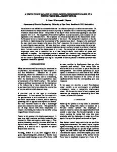
failure of grasp. Using tactile sensors needs to do continuous replanning to reach the final grasp state, which is time consuming. Considering all the advantage and disadvantage of using partial information and tactile sensors, and the inspiration from the PR2 and Baxter robots, we propose to use two 3D sensors distributed as the camera sensor structure used by the PR2 and Baxter robots (seen as Fig.1) to construct a partial point cloud. Then, exploration on the partial point cloud is carried out to find the most reliable and stable grasp. Unlike the traditional exploration, we propose to explore the unknown object through a partial point cloud in the virtual environment. Traditionally, exploration grasping methods require the robot to move around the object and find the best grasp configuration, like[16], which requires significant time consumption. In this paper, we try to decrease the grasp computation time within 1 or 2 seconds. Using two 3D inputs can actually build a “big” partial point cloud for the unknown objects. The robot will grasp the unknown object between the two sensor points, which can greatly decrease the uncertainty. And the “big” partial cloud will not greatly increase the computation time. In order to find a stable grasp, we created a force balance search method to carry out force balance exploration on the partial point cloud. A best stable grasp is returned as the final grasp. All the force balance exploration is executed on the partial point cloud. There is no need to drive the robot moving to another viewpoint or do replanning for the robot hand, which can greatly accelerate the process of unknown object grasping.
transformation matrix from the hand sensor coordinate system (HASCS) to the ECS can be obtained. Thead and Thand are used to describe the two transformations from the two SCSs to the WCS, as can be seen in the equation (1). Fig.2 demonstrates the whole distribution of the coordinate systems mentioned above. The inside of the dashed line means the robot, consisting of a robot arm and the robot head. The green ASUS Xtion sensor is installed on the robot head, another ASUS Xtion sensor (in black) is mounted on the end-effector of the robot arm.
This paper is organized as follows. Section II contains a detailed explanation of our algorithm, Sections III shows the simulation results, Section IV is a discussion about two grasping methods, Section V is about our future work and section VI is the conclusion.
Fig.3 shows the transformation of the point clouds obtained from the two 3D sensors. Fig. 3(a) and (d) are the raw point clouds from the two 3D sensors, (b) and (e) are the isolated point clouds of the target object in the SCS. (c) and (f) are the transformed point clouds in WCS. (h) is the registered point cloud of the target object in the WCS. (i) shows the registered point cloud in the object coordinate system (OCS).
Thead = THESCS_BCS Thand = THASCS_ECS * TECS_BCS
(1)
Fig. 2. Distribution of all the coordinate systems. The dashed line means the robot consisting of the robot arm and the robot head, green cuboid and black cuboid respectively stand for the sensor on the robot head and the sensor on the robot hand.
Fig. 1. Two illustrations of robots using two camera sensors.
II. DETAILED ALGORITHM A. Construction of the partial model of the target object Two raw point clouds from the two 3D sensors mounted on the robot head and robot hand are first downsampled in order to accelerate the processing speed by using voxel grid downsampling and distance filtering. Then, the RANSAC (Random Sample Consensus) method is used to isolate the point cloud of the target object by removing the supporting plane. So far, the two point clouds are separately located at their own sensor coordinate systems (SCS). Further analysis requires to transfer the two point clouds from the SCS to the world coordinate system (WCS). Joint position information from the encoders inside the robot joints can be used to calculate the real time transformation matrix from the end-effector coordinate system (ECS) to the base link coordinate system (BCS). The transformation matrix from the head sensor coordinate system (HESCS) to the BCS can be acquired through calibration. Using the same method, the
Fig. 3. The process to obtain the registered partial point cloud of the target object in the object coordinate system.
B. Establishment of the OCS Fig.4 demonstrates the establishment of the object coordinate system (OCS). Principal component analysis (PCA) is used on the registered point cloud (Fig.3 (h)) of the target object in the WCS to calculate the principal axis, which will work as the Y axis of the OCS. In order to work out the X axis of the OCS, a random point on the principal axis (Rp) and the Sensor point on the robot hand (Sp) need to be known first. The Rp point can be extracted on the positive principal axis. The position of Sp point can be obtained through the feedback information from the encoders in the joints of the robot. The calculation of the OCS is according to equation (2). The registered point cloud in the object coordinate system (OCS) can be seen in Fig.3 (i). 8
OcY = Oc Rp Oc Sp × Oc Rp O= cX Oc X × OcY cZ O=
carried out in the configuration free space C free (seen as equation (4)).
(2)
n
C free = {q | q ∈ Cobj ∧ q ∉ ΓΓi }
(4)
i =1
In order to find a stable and reliable grasp, we propose to search in the configuration space of the target object, check the force balance quality for every possible grasp configuration, and then choose a grasp with the best force balance. In the SE(3) group, the number of possible configuration of the fingers is almost infinite. Some grasp tools like OPENRAVE or GraspIt try to configure fingers in the Cobj . This kind of grasping tools usually requires full 3D mesh model of the target object. They try to generate random grasps in SE(3) and evaluate the grasp quality until the robot finding a suitable grasp. This process is time consuming and requires the full 3D model. Actually, in many robot application it is impossible to get a full 3D model, for example, the objects in the fridge. In order to simplify the computation and accelerate the searching process, we propose to calculate the force balance on the local point cloud directly, instead of on a mesh model.
Fig. 4. Establishment of the object coordinate system (OCS).
C. Construction of all virtual object coordinate systems After the previous steps, we already get the registered partial point cloud of the target object. How to find a suitable grasp on the partial point cloud? Problem of grasping unknown objects can be understood as finding a proper grasping configuration for the robot. From the perspective of motion planning, the grasping problem can be formulated as motion planning under the work space of robot and the configuration space of the target object. In the 3D world, the configuration space ( C space) of the target object ( Cobj ) actually follows a SE(3) group. An object configuration in Cobj is named q , q = {qx , q y , qz , qq 1 , qq 2 , qq 3 } where qx , q y ,
As can be seen in Fig.5, if the configuration of the hand is in SE(2), it will greatly cut the search number. Illuminated by SE(2), the principal axis of the target object is used to guide the search process. Just as described in Fig.5, on the XOZ plane of the OCS, the configuration of the robot hand is actually a rotation around the Y axis. Then the configuration of the hand can be considered as Γ[q yi | qqi ] in the SE(2)
qz and qq 1 , qq 2 , qq 3 corresponds coordinates of position in the Cartesian frame and coordinate along the rotational orientation. Ο[q] , Ο[q xyz ] and Ο[qq ] are the corresponding target object at configuration q .
group. In order to get the point cloud in every grasp configuration, we use series of virtual viewpoints (shown as in Fig.6) distributed around the principal axis of the target object. ∆θ is employed as the fixed rotation step.
Grasping can be thought as the configuration of the fingers ( Γi , i = 1, 2,..., n , n is the number of fingers) of the robot in
the Cobj . Γi is formed by independent fingers and
corresponds to f i , i = 1, 2,..., n in the work space ( W space). The configuration of fingers Γi can be considered as
configuration obstacles in Cobj .
From the perspective of motion planning, the grasping algorithm needs to calculate a pregrasp. And then the robot tries to approach the target object by using the pregrasp. Usually, for grippers without tactile sensors, the grasping algorithm needs to work out the final grasp state. After obtaining this state, what the robot needs to do is just to close its gripper. That is the whole procedure of the unknown object grasping. the equation (3) shows the final grasp configuration. This equation means the finger configuration belong to the target object configuration and fingers should have intersection so that the gripper can grasp the target object.
= Γi {q | q ∈ Cobj ∧ (Ο[q] fi ≠ f )}
Fig. 5. Configuration of robot hand in SE(2).
(3)
After the robot obtained the final grasp configuration, the robot needs to work out an collision free trajectory to drive the robot arriving at the grasping point. This trajectory planning is
Fig. 6. Virtual viewpoints distribution. ∆θ is the searching step. The most left and most right black point correspond to the viewpoints of the robot head and robot hand. 9
At every virtual viewpoint, a virtual 3D sensor is defined. The concept of virtual viewpoints is created to make the description easier. At every virtual viewpoint, using what has been described in Fig.4, we can build a virtual object coordinate system (VOCS). In every VOCS, we can get a local point cloud directly facing to the virtual 3D sensor. Fig.7 shows all the local point clouds from the position qq 0 of the 3D sensor on the robot hand to the position qq 1 of the 3D sensor on the robot head. qq 0 and qq 1 means the start point of hand configuration and the end point of the hand configuration in SE(2) group with the searching step ∆θ . At every virtual object coordinate system, a straight line ( lvirtual ) can be obtained by connecting the virtual viewpoint and the object center. Hand sensor is chosen as the start virtual viewpoint. Then lvirtual is projected to the XOY plane of the VOCS of the
The force balance computation on O[qq ] can be divided into two parts, that is the force balance on XOY plane ( FXOY ) and the force balance on XOZ plane ( FXOZ ). All these computation is carried out in every VOCS. The purpose of force balance computation on the XOY plane is to find Ο[q ym | qq ] ,which stands for the maximum force balance among all the Ο[q yi | qq ] ( i is a variable, i = 1, 2,..., n ). The purpose of force balance computation on the XOZ plane is to find the maximum force balance Ο[q ym | qq m ] among all the
Ο[q ym | qq h ] , θ h starts from θ 0 to θ 1 with the step of ∆θ (can be seen in Fig. 6). Equation (5) shows the force balance computation method. = FXOY max{F {O[q yi | qq ] ∧ O[q yi | qq ] ∈ O[ qq ]}} = FXOZ max{F {O[q ym | qq h ]}}
hand sensor to get the project line ( l projected ). qq is the angle
between l projected to the Z axis of the VOCS. q= n * ∆q , n q
(5)
D. Force balance computation on the XOY plane
means the nth virtual viewpoint and n starts from 0.
The computation of force balance on the XOY plane ( FXOY ) starts from the local point cloud O[qq ] in the VOCS. Fig.8 is a random object configuration at qq and it will be used to explain the specific algorithm. Firstly, O[qq ] is projected to XOY plane of the VOCS. The projected point cloud ( O[qq ] p ) is shown as Fig.9 (a). Then, the concave hull is employed to extract the contour of O[qq ]c , the concave hull contour is shown as Fig.9 (b). In order to make it convenient for the following computation, a straight line is used to search along Y axis of the VOCS. The straight line is distributed along the Y axis at an interval of δ (shown as Fig.9 (c)). The most left and most right points are extracted to build a point cloud used for force balance computation. It is called force balance computation point cloud ( O[qq ] f ) seen as Fig.9 (d). Then the
Fig. 7. The distribution of all the local virtual point clouds in all VOCSs.
Fig. 7 demonstrates the distribution of all the local virtual point clouds in all VOCSs. After we get all the local virtual point clouds, Force balance computation is carried out on every local point cloud O[qq ] . Ο[q yi | qq ] ( i is a variable,
i = 1, 2,..., n ) is used to represent the ith local point cloud of the robot hand configuration. And it’s obvious this local point cloud belongs to O[qq ] , that is Ο[q yi | qq ] ∈ Ο[qq ] . Fig.8
grasp range of the robot hand is taken into consideration. d is used to represent the grasp range of the robot hand. If the distance between the left point and the right point is smaller than d, then the two points are saved. Finally, all the saved points can construct a point cloud as Fig.9 (e) and it is called point cloud within grasping range ( O[qq ]w ). After that, discontinuity computation is carried out to find all the discontinuity. In Fig.9 (e), every rectangular means a possible grasp. The algorithm will search from the top to the bottom to check every possible grasp ( O[qq ]wi , i = 1, 2,..., n ). The main purpose of this step is to remove the grasp candidates with large discontinuity. Large discontinuities like circumstances in Fig.9 (f) greatly increase the possibility of grasp failure. In Fig.9 (f), the distance of the two adjacent points is represented by ∆x and ∆y . A threshold ( ∆xth ) is set by the algorithm, if ∆x > ∆xth , then it means that a big discontinuity exists. Big discontinuity may lead to the failure of grasp, so the grasp needs to be abandoned. After the above steps, a comparably reliable graspable region ( O[qq ]r ) is found as shown in Fig.9 (g). Then force balance computation is carried out on O[qq ]r . From the top to the bottom, Force balance computation is executed on every grasp candidate ( O[qq ]ri , i = 1, 2,..., n ) shown as Fig.9 (h). Fig.9 (i) is a random grasp candidate
shows the description of O[qq ] and Ο[q yi | qq ] . O[qq ] means the whole point cloud (the blue and green point cloud in Fig.8). Ο[q yi | qq ] means the point cloud covered by the ith hand configuration. The red, blue and the green rectangular can respectively represent the Ο[q yi | qq ] , Ο[q yi +1 | qq ] and
Ο[q yi + 2 | qq ] .
Fig. 8. Description of O[qq ] and Ο[q yi | qq ] , O[qq ] means the whole point cloud in this virtual object coordinate system. Ο[q yi | qq ] means the ith hand configuration on the point cloud of O[qq ] . 10
best force balance can be extracted. The extracted point clouds can be found in Fig.12(a). Fig.12(b) is a top view. From O[qq 0 ] to O[qq 1 ] , every O[qq ] has its own virtual coordinate system. Force balance computation FXOZ is carried out in every virtual coordinate system.
O[qq ]rr abstracted from the O[qq ]r . Two straight lines can be fit out on the two grasp sides of the O[qq ]rr . Least squares fitting is used to fit the straight lines. If the function of the straight line is = y kx + b , then k and b can be worked out according to least squares fitting method, seen as the equation (6). The angle ( β ) between the two fitting straight lines is used to evaluate the force balance quality. Then the smallest β among all the O[qq ]rr means the best grasp on XOY plane. The blue points in Fig.9 (j) means the grasp with smallest angle β min . Fig.10 shows the result of force balance computation on the O[qq ]r . There are 12 grasp candidates on O[qq ]r , The smallest angle is 0.357629 radian when the search number comes to 10, that is O[qq ]r10 . n n 1 n xi yi − ∑ xi ∑ yi ∑ n =i 1 =i 1 k = = i n1 n 1 n 2 x xi ∑ xi − ∑ ∑ i n i 1 =i 1 = =i 1 1 n 1 n yi − k ∑ xi = b ∑ n i 1= ni1 =
Fig. 11. The result of force balance computation on the XOY plane from O[qq 0 ] to O[qq 1 ] . (b) is an enlarged image of (a) , the colored points except the blue points in (b) stand for all the grasp candidate with the best force balance on the XOY plane in every virtual coordinate system.
(6)
Fig. 12. Abstract point cloud Ο[q ym | qq ] according to the result of force balance on XOY plane in every virtual coordinate system.
Fig. 13 gives an example of force balance computation on the XOZ plane. Fig.13(a) shows the extracted point cloud Ο[q ym | qq ] according to the previous force balance computation result on the XOY plane. The red points in Fig.13(b) means the grasp with the best force balance on the corresponding point cloud within grasping range ( O[qq ]w ). Pr is used to represent the red point cloud, and it can be divided into two parts, the left part Prl and the right part Pr r . The both
Fig. 9 The process of force balance computation on XOY plane of the VOCS.
sides of the Pr are used to extract the area which will contact with the fingers when the robot try to grasp the target object. If the total number of points in Pr is 2k, then Prl starts from 0 to
2k-2, then Pr r starts from 1 to 2k-1. Then the equation (7) is used to abstract the left and right contact region and n is from 0 to k-2. The two inequality in equation (7) are used to extract the green and purple areas shown in Fig. 14.
Fig.10. The result of force balance calculation on XOY plane of the VOCS.
Fig. 11(a) shows the result of force balance computation on the XOY plane from O[qq 0 ] to O[qq 1 ] . The blue points means all the corresponding O[qq i ] f for every point cloud of the object in the virtual object coordinate system from O[qq 0 ] to O[qq 1 ] . Fig. 11(b) is a partial enlarged image, it shows all the grasp candidates with the best force balance on the XOY plane. E. Force balance computation on the XOZ plane According to the result of force balance computation on the XOY plane, the corresponding point clouds which have the
Fig. 13. An extracted point cloud with the best force balance on the XOY plane of its virtual coordinate system. 11
( X 2 n ≤ X i ≤ X 2 n + 2 ) || ( X 2 n + 2 ≤ X i ≤ X 2 n ) ( X 2 n +1 ≤ X i ≤ X 2 n + 3 ) || ( X 2 n +1 ≤ X i ≤ X 2 n + 3 )
(7)
Fig. 14. Extract the left and right contact region to do force balance computation on the XOZ plane.
Fig. 15. The result of force balance calculation on XOZ plane from O[qq 0 ] to O[qq 1 ]
In Fig.14, all the points (the blue, the green and the purple) represent the extracted point cloud Ο[q ym | qq ] , the green and
of the UR5 arm in Gazebo. The other sensor is installed on robot head. A three finger gripper is installed at the end of the arm to work as grasping tool. The Simulation setup can be seen as the first column in Fig.16. The two sensors will acquire the data of the target object and the data will be processed according to the steps described in section II.
the purple respectively represent Prl and Pr r , the red points are the same as the red points in Fig.13. Fig.14(a) is an overview, (b) is a side view. After the Prl and Pr r is obtained, the average Z1 and Z 2 are worked out, and the difference (
∆Z seen as equation (8)) between Z1 and Z 2 is used to evaluate the force balance on the XOZ plane. Fig.15 shows the result of force balance computation on the XOZ plane from O[qq 0 ] to O[qq 1 ] . Force balance quality is best when θ i comes
In order to verify our grasping algorithm, several objects in different geometry shape are chosen to do simulations. All the tested objects can be seen in the first column in Fig.16. In order to prove the effectiveness of our algorithm, the tested objects are placed at different positions and orientations. The second and third column show the result of force balance exploration. The fourth column shows the best grasp in OCS found by our grasping algorithm. The last column shows the grasp execution in the configuration free space C free . Table I shows the result of force balance exploration. The second row shows the force balance result of the final grasp configuration shown in last row of the table. It is easy to find that all those five objects have very good force balance performance on both the XOY plane and the XOZ plane, which can make sure the grasp is stable and reliable. The coresponding overview about point sets and the grasp computation time is shown as the Table II. The algorithm can quickly process the partial point cloud and output the final grasp within 1 or 2 seconds (varying according to the point sets). The simulation demonstrated the effectiveness of our grasping algorithm.
to θ 4 , therefore, this configuration will be chosen as the final grasping configuration.
1 n 1 n zi − ∑ zi ∑ n i 1= ni1 =
∆Z= Z left − Z right=
(8)
III. SIMULATION In order to test the algorithm, various objects are chosen to conduct simulation to determine the grasping performance. The simulation system consists of Robot Operating System(ROS), Gazebo (an Standalone Open Dynamics Engine based simulator) and MoveIt! (an state of art software for mobile manipulation, incorporating the latest advances in motion planning, manipulation, 3D perception, kinematics, control and navigation).
Table II. Simulation results of the grasp computation time
As we said in the abstract, this algorithm uses two 3D sensors to build a partial point cloud to carry out force balance exploration. In the simulation, two Asus Xtion PRO Live sensors are used. One 3D sensor is installed on the end effector
Unknown Objects points Time(s)
Spray bottle 9801 1.068
Table tennis bracket 1358 0.515
Vase 19583 1.653
Shampoo bottle 7059 0.994
Oatmeal box 11214 1.198
Table I. Simulation results of the final grasp configuration and the corresponding force balance coefficient on the XOY plane and the XOZ plane
xoy
xoz
xoy
xoz
xoy
xoz
xoy
xoz
xoy
xoz
0.3576
0.0002
0.0618
0.0021
0.0034
0.0005
0.0003
0.0054
8.5e-6
0.0021
12
Fig. 16. Simulation results.
moving around the target object to find the maximum curvature. Then, the maximum curvature works as the grasping point. This kind of grasping algorithm can find grasp on the partial view of the object and does not require the robot moving around the whole object to acquire information. It is applicable for all kinds of grippers include underactuated gripper and it is very cheap. However, driving the robot moving around the object is also time consuming. In addition, comparing with the tactile sensor based grasping algorithm and our grasping algorithm, EFD method is not stable enough (seen as the blue points in bottom picture of Fig.17 (b)). If the robot grasps the two blue points, the spray bottle will have a rotation, which may lead to the failure of the grasp. Our grasping algorithm (Fig.17 (c)) uses the inputs from two 3D cameras to construct a partial point cloud of the target object. Virtual viewpoints are set between the two 3D cameras. Force balance computation is carried out at the virtual viewpoints, which does not need to drive the robot moving around the target object. It can quickly find the grasp with the best force balance (seen as the bottom left picture in Fig.17 (c)). Comparing with tactile sensor based grasping and the EFD based exploration, our algorithm is applicable for both underactuated gripper and dexterous hand. The force balance exploration is carried out on the partial point cloud in the virtual object coordinate systems. Therefore, the robot using our algorithm does not need to move the robot around the object or do replanning for fingers. It has a much better performance in time efficiency and grasping stability.
IV. DISCUSSION This section is a discussion about 3 typical exploration used for unknown object grasping. The first one is tactile sensor based exploration[15]. Many tactile sensors are installed on the fingers of a gripper (seen as Fig.17(a)). This kind of grasping is usually combined with robot vision (2D vision or 3D vision). Vision is used to find a grasp and tactile sensors are used to obtain information of force and torque to continually revise the grasp when the robot executes the grasp found by vision. This revise is usually called reactive grasping, which is actually doing continuous replanning for finger motion until the best force closure grasp is found. Tactile sensors are pretty helpful to explore the unseen part of the target object to reduce the uncertainty appearing during the execution of a grasp. Another obvious advantage of using tactile sensors is that it can get a better force closure grasp, which can make the grasp action more stable and reliable. However, tactile sensors are usually very expensive and doing replanning for finger motion is time consuming. In the meantime, tactile sensor based grasping is not applicable for many underactuated gripers which usually can only open and close. But underactuated grippers are widely used in many robotic occasions. The second exploration method is using eye in hand system, [16] is a very good exploration based on only one camera (seen as the top picture of Fig.17 (b)). The contour of every image is extracted to work out the maximum curvature by using elliptic Fourier descriptors (EFD). Extremum Seeking Control (ESC) is used to drive the robot 13
used to do simulations. Our algorithm can quickly process the partial point cloud and output the final grasp within 1 or 2 seconds (varying according to the point sets). The simulations demonstrated the effectiveness of our grasping algorithm. ACKNOWLEDGMENT The work leading to these results has received funding from the European Community’s Seventh Framework Programme (FP7/2007-2013) under grant agreement n° 609206.
(a) (b) (c) Fig. 17. Three typical exploration for unknown object grasping, (a) tactile sensor based exploration, (b) one 2D camera based exploration, (c) Two 3D cameras based exploration.
REFERENCES [1]
V. FUTURE WORK
[2]
Our future work will mainly focus on the grasping of large scale complex unknown objects, which is a big challenge in robotic grasping field. A promising way to solve the problem of large scale complex unknown object grasping is using decomposition, which conforms well with human intuition about grasp searching based on object parts. Point cloud segmentation is a commonly used method to decompose unknown objects. The existing 3D segmentation techniques of point cloud is to compute the surface features which contrast boundary and non-boundary points and then to decompose the object into parts at the boundary points. The key issue of point cloud segmentation is how to reliably locate the part boundaries. Fig.18 is a segmentation example of a chair by using region growing segmentation. Our previous grasping algorithm[17] and the grasping algorithm in this paper can be employed to work out a suitable grasp by using force balance optimization on a local object part. Region growing segmentation is a useful method to segment point cloud, however, it requires manually inputting several parameters. Therefore, our future work will mainly concentrate on the development of a new automatic segmentation algorithm specially designed for the purpose of large scale complex unknown object grasping.
[3] [4] [5]
[6] [7] [8] [9] [10] [11] [12] [13] [14] [15] [16]
Fig. 18. Future work
[17]
VI. CONCLUSION In this paper, a novel grasping exploration algorithm for unknown objects is presented. Using two 3D sensors, a partial point cloud of the target object can be quickly constructed by using the two 3D inputs. Force balance exploration is then carried out on the partial point cloud. This algorithm can quickly work out the grasp with best force balance and output the grasp position and orientation to drive the robot grasping the target object promptly. In order to verify the effectiveness of our algorithm, several objects commonly used by other grasping algorithms with different geometric shapes were 14
Kai Huebner, Danica Kragic, “Selection of robot pre-grasps using box-based shape approximation,” in IROS, 2008, pp. 1765–1770. Bone GM, Lambert A, Edwards M, “Automated modeling and robotic grasping of unknown three dimensional objects,” in ICRA, 2008, pp. 292–298. E. Lopez-Damian, D. Sidobre, and R. Alami, “A grasp planner based on inertial properties,” in ICRA, 2005, pp. 754–759. H.-K. Lee, M.-H. Kim, and S.-R. Lee, “3d optimal determination of grasping points with whole geometrical modeling for unknown objects,” Sensors and Actuators, vol. 107, 2003, pp. 146-151. K. Yamazaki, M. Tomono, and T. Tsubouchi, “Picking up an Unknown Object through Autonomous Modeling and Grasp Planning by a Mobile Manipulator,” Field and Service Robotics, Springer Berlin / Heidelberg, 2008, vol. 42, pp. 563–571. A. T. Miller, S. Knoop, H. I. Christensen, and P. K. Allen, “Automatic grasp planning using shape primitives,” in ICRA, 2003, pp. 1824–1829. Hao Dang and Peter K. Allen, “Semantic Grasping: Planning Robotic rasps Functionally Suitable for An Object Manipulation Task,” in IROS, 2012, pp. 1311-1317. Goldfeder C, Ciocarlie M, Peretzman J, Dang H, Allen PK, “Data-driven grasping with partial sensor data,” in IROS, 2009, pp. 1278–1283. Goldfeder C, Ciocarlie M, Dang H, Allen PK, “The Columbia grasp database,” in ICRA, 2009, pp. 1710–1716. Collet A, Berenson D, Srinivasa SS, Ferguson D, “Object recognition and full pose registration from a single image for robotic manipulation,” in ICRA, 2009, pp. 48–55. R. Platt Jr., A. H. Fagg, and R. A. Grupen, “Nullspace composition of control laws for grasping,” in IROS, 2002, pp. 1717–1732. J. Felip and A. Morales, “Robust sensor-based grasp primitive for a three-finger robot hand,” In IROS, 2009, pp. 1811–1816. K. Hsiao, P. Nangeroni, M. Huber, A. Saxena, and A.Y. Ng, “Reactive grasping using optical proximity sensors,” in ICRA, 2009, pp. 2098– 2105. M. Prats, P. Martinet, S. Lee, and P.J. Sanz, “Compliant physical interaction based on external vision-force control and tactile-force combination,” In MFI, 2008, pp. 405–410. K. Hsiao, S. Chitta, M. Ciocarlie, and E. G. Jones, “Contact-reactive grasping of objects with partial shape information,” in IROS, 2010, pp. 1228–1235. Calli B, Wisse M, Jonker P, “Grasping of unknown objects via curvature maximization using active vision”, in IROS, 2011, pp. 995-1001. Qujiang Lei, Martijn Wisse, “Fast grasping of unknown objects using force balance optimization”, in IROS, 2014, pp. 2454–2460.