SIMULATION http://sim.sagepub.com
Usefulness of Software Architecture Description Languages for Modeling and Analysis of Federates and Federation Architectures Frederic D. McKenzie, Mikel D. Petty and Qingwen Xu SIMULATION 2004; 80; 559 DOI: 10.1177/0037549704050185 The online version of this article can be found at: http://sim.sagepub.com/cgi/content/abstract/80/11/559
Published by: http://www.sagepublications.com
On behalf of:
Society for Modeling and Simulation International (SCS)
Additional services and information for SIMULATION can be found at: Email Alerts: http://sim.sagepub.com/cgi/alerts Subscriptions: http://sim.sagepub.com/subscriptions Reprints: http://www.sagepub.com/journalsReprints.nav Permissions: http://www.sagepub.com/journalsPermissions.nav
Downloaded from http://sim.sagepub.com at PENNSYLVANIA STATE UNIV on April 14, 2008 © 2004 Simulation Councils Inc.. All rights reserved. Not for commercial use or unauthorized distribution.
Usefulness of Software Architecture Description Languages for Modeling and Analysis of Federates and Federation Architectures Frederic D. McKenzie Department of Electrical and Computer Engineering Old Dominion University Norfolk, VA 23529
[email protected] Mikel D. Petty Qingwen Xu Virginia Modeling Analysis and Simulation Center Old Dominion University Norfolk, VA 23529 Software architecture is high-level software design dealing with the structure and organization of large software systems. Architecture description languages (ADLs) are languages designed to represent software designs at the architecture level. ADLs are not widely used in the development of simulation systems. This research investigates the utility and effectiveness of ADLs for architecture-level design and analysis of simulation systems. Experimental applications of two ADLs to the specification and analysis of simulation architectures were conducted. Rapide was used to model the EnviroFed federation architecture and analyze data volume with and without interest management. Acme was used to model the ModSAF federate architecture and to analyze execution time at the component and federate levels in ModSAF. The experiments showed that ADLs could be used to discover important features of simulation system architectures. Keywords: Software architecture, architecture description languages, performance analysis
1. Introduction
to the task of representing two existing military simulation software systems, one at the federation level and one at the federate level. These experiments are among the first applications of general-purpose ADLs to simulation systems. This article has three main sections. First, an introductory description of software architecture and software architecture description languages is provided. Second, the project goals and methodology are explained. Finally, the architecture model and the results of the runtime performance analysis based on the model are presented for each experiment.
Software architecture is high-level software design dealing with the structure and organization of large software systems. Architecture description languages (ADLs) are languages that represent software designs at the architecture level, typically in terms of computational components and interactions among them. Formal tools and techniques for software architecture design, including ADLs, have so far been underused in the modeling and simulation development community. A motivating question of this research was whether there was a reason for the underutilization (i.e., whether there was some characteristic of simulation systems that made conventional ADLs unsuitable for them). To examine the utility and effectiveness of using ADLs for the architecture-level design of simulation systems, two different ADLs were experimentally applied SIMULATION, Vol. 80, Issue 11, November 2004 559-576 © 2004 The Society for Modeling and Simulation International DOI: 10.1177/0037549704050185
2. Software Architecture This section introduces software architecture and software architecture description languages and discusses their application to simulation systems. | | | | |
2.1 Introduction to Software Architecture What is software architecture? Perhaps because the discipline of software architecture is relatively new, no two
Downloaded from http://sim.sagepub.com at PENNSYLVANIA STATE UNIV on April 14, 2008 © 2004 Simulation Councils Inc.. All rights reserved. Not for commercial use or unauthorized distribution.
McKenzie, Petty, and Xu
definitions of software architecture are quite identical, but most are substantially in agreement. Software architecture involves the description of elements from which systems are built, interactions among those elements, patterns that guide their composition, and constraints on these patterns. . . . The architecture of a software system defines that system in terms of computational components and interactions among those components [1]. The essential idea of software architecture is that software at a high level of abstraction can be described as a number of distinct elements or subsystems together with their interconnection and interactions [2]. A software architecture describes a software system as a configuration of components and connectors [3]. Software architecture can be understood as the subset of software design that is concerned with the software’s structural aspects. Those structural aspects are centered on the components of the system and the connections between them. Software architecture can also be understood as the highest (least detailed) level of software design. At the highest level of software design, most details are eliminated from consideration, leaving or revealing the structure. Detailed software design issues such as specific algorithms and data structures, while important, are not generally the concern of software architecture, unless they affect the overall organizational structure of the software system. Software design in general, and software architecture in particular, includes the notion of design patterns. Design patterns are design and organizational structures that have proven to be useful, flexible, or efficient and reappear in multiple systems [4]. An architecture design pattern is “an abstraction over a family of software architectures” [3]. It is possible to “identify a set of architecture patterns, or styles, that currently form the basic repertoire of a software architect” [1]. Many architecture patterns have been developed and promulgated as software architects, and system designers have recognized architecture patterns that are consistently useful. A basic principle of architecture design is that system or component architectures at one design level may be composed into larger systems at a higher level and/or decomposed into subsystems at lower levels. Indeed, software architectures are often developed in practice by composition. Software architecture patterns are in many ways patterns of composition. An architecture pattern describes a way to compose components, connectors, and other architecture objects. As stated in Shaw and Garlan [1], “Composing a system from subsystems is unlike programming the algorithms and data structures that lie within the primitive
subsystems”; the composition activity takes place at the architecture level. 2.2 Specifying Software Architectures Descriptions of large software systems often include a representation of the system architecture, which is valuable, but those representations typically use an informal graphical notation known as a “box-and-line” diagram. In boxand-line diagrams, boxes usually represent system components or layers, and lines usually represent some data flow or control connection between the components. Such diagrams are ubiquitous, widely understood at a general level, and certainly better than nothing. Unfortunately, because box-and-line diagrams are informal, the semantic meanings of the boxes and lines vary from one box-and-line diagram to the next [5]; indeed, they often vary within a single diagram. Textual description is also used informally in software architecture practice. The text may mention a particular architecture pattern (e.g., “client-server”); it is rare see a detailed explanation of how the architecture being described is consistent with, and differs from, the named pattern. While such descriptive text is again certainly better than nothing, like informal box-and-line diagrams, it is generally ambiguous and not amenable to analysis. Less informal than box-and-line diagrams, the Unified Modeling Language (UML) is a graphical language in which various aspects of a system are represented by different types of diagrams [6]. UML can represent significant structural aspects of a system that have been defined to be software architecture; for example, the UML class diagrams show the packages and component classes of a system, and UML interaction and state chart diagrams show the behavior of the components. While it is powerful and widely used, UML may yet still be too broad and not deep enough for use specifically at the architecture and architecture design levels. Formal specification languages (FSLs) are characterized by their mathematical formality, including precisely defined syntax and unambiguous semantics. FSLs are intended to be sufficiently formal to be the subject of logical analysis, proofs of correctness, and automated reasoning. For example, the FSL Z (pronounced “zed”), developed primarily at the University of Oxford and perhaps the most widely used FSL, is based on first-order logic and set theory [7]. The reasoning potential provided by the formality of FSLs is appealing. However, the actual structure of the architecture pattern can be difficult to discern in an FSL specification, and the nonintuitive and unfamiliar syntax of FSLs can be an obstacle to their use by many practicing software architects. FSLs are generally more often used to specify the details of systems at the computation or interface design levels rather than the architectural levels. Architecture description languages (ADLs) have been developed to avoid the shortcomings of informal architecture specification methods and general-purpose design
560 SIMULATION Volume 80, Number 11
Downloaded from http://sim.sagepub.com at PENNSYLVANIA STATE UNIV on April 14, 2008 © 2004 Simulation Councils Inc.. All rights reserved. Not for commercial use or unauthorized distribution.
SOFTWARE ARCHITECTURE DESCRIPTION LANGUAGES
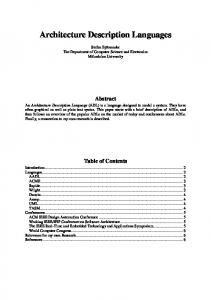
notations. An ADL is “a notation that allows for a precise description of the externally visible properties of a software architecture” [3]. In particular, ADLs “provide constructs for specifying architectural abstractions in a descriptive notation. They provide mechanisms for decomposing a system into components and connectors, specifying how these elements are combined to form a configuration and defining families of architectures or styles” [8]. They generally contain language elements for components and connections that define those types of objects rigorously enough to perform architectural reasoning about them without delving too deeply into the lower-level details of computation and interfaces.ADLs are “aimed at giving practitioners better ways of writing down architectures so that they can be communicated to others and in many cases analyzed with tools” [1]. ADL examples include Darwin [9, 10], Aesop [1, 11], Unicon [1], Wright [1, 12], Rapide [13, 14], and Acme [15, 16]. It has been claimed that six types of ADL language elements form a sufficient vocabulary for expressing any software architecture [1]. They are listed below and illustrated in Figure 1. 1. Component. Components perform computation and retain state; they are “independent units of computation” [8] and “loci of computation and state” [17]. Components correspond to the boxes in informal box-and-line diagrams. They are “black box entities that encapsulates services behind well-defined interfaces” and “static abstractions with plugs” [3]. Components may have a type, such as “filter” or “manager”; these types are analogous to a type definition in a conventional programming language or a class definition in an object-oriented language. Components may be primitive, not further decomposable at the architecture level, and generally implemented as compilation units in a programming language, or composite, formed by composing other architecture objects. Components have interfaces, through which they interact with other parts of the system. 2. Connector. Connectors are relations between components; they “represent interactions among components” and “model interactions among components and rules that govern those interactions” [8]. They are not objects to be connected in an architecture; they do the connecting. They embody the expected patterns of communication and interactions between components. Connectors represent any type of interaction, such as data flow and control, between components. Connector descriptions may specify which types of interactions they represent and which protocols are associated with those interactions. Unlike components, connectors do not generally correspond to compilation units. Like components, connectors may be primitive or composite, and connectors may be typed, with the types definable in
Composite component A Configuration Binding
Port of A
Component B
Ports of B
Connector C
Roles of C
Component D
Ports of D
Binding
Port of A
Figure 1. Generic architecture description elements. Adapted from Shaw and Garlan [1].
the ADL; “pipeline” and “event” are examples of connector types. 3. Port. A port is a component’s point of interaction with the rest of the architecture. Ports may have interface and protocol details associated with them. Ports on components connect to roles on connectors (roles are defined next). 4. Role. A role is a connector’s point of interaction with the rest of the architecture. Roles may have interface and protocol details associated with them. Roles on connectors connect to ports on components. 5. Representation. For a composite object (component or connector), a representation is a description of the subordinate objects that have been composed to form the composite object. 6. Binding. For a composite object, a binding specifies the mapping or correspondence between the interfaces (ports or roles) of the objects that have been composed and the external interfaces of the composite object. Using an ADL is similar to using a general-purpose programming language or specialized modeling language in both mechanics and difficulty. Different ADLs are defined in textual or graphical forms (or both in some cases). Creating an architecture specification in an ADL requires entering the text or arranging the graphical elements as one would do for a program in a general-purpose language. The elements of the ADL are generally those architectural elements just listed, so ADL statements (or symbols) define the attributes and characteristics of components, connectors, and so on in the architecture, especially how the elements are linked. Many of the features of an ADL as a language would seem familiar to most programmers; for example, some ADLs allow the definition of types (and type hierarchies) of components and connectors, with specialized attributes and characteristics, for later use. ADLs Volume 80, Number 11
Downloaded from http://sim.sagepub.com at PENNSYLVANIA STATE UNIV on April 14, 2008 © 2004 Simulation Councils Inc.. All rights reserved. Not for commercial use or unauthorized distribution.
SIMULATION
561
McKenzie, Petty, and Xu
also have features specialized for architectural specification and, in this way, are similar to specialized modeling languages. Once an architecture specification has been entered in an ADL, it can be processed in various ways, including simulating the architecture (as for Rapide, described below) or statically analyzed (as for Acme, also described below). ADLs provide greater formality of representation than informal box-and-line diagrams during the design process. This forces the architect to consider and specify his or her design for the system with more precision, thereby uncovering architectural problems earlier. ADLs increase the likelihood of correctly designed connections (i.e., interfaces, protocols, and data flows) between the components (i.e., modules, algorithms, and data structures) in an architecture [1]. ADLs also allow more powerful analysis of designs. ADLs that are sufficiently formal and rigorous so as to express architectural properties in unambiguous ways provide a basis for reliable reasoning, manual and automated, about the properties of software systems. Indeed, some ADLs support the simulation of an architecture represented in the ADL. The goal is that such ADL-enabled reasoning and simulation will reveal architectural properties earlier in the development cycle, when changes are easier and less costly, than would occur otherwise [1]. 2.3 Software Architecture of Simulation Systems The architecture of a software system can depend on both the computational requirements of the system and the application domain of the system. Simulation systems are generally software systems, at least in part, so our discussion of software architecture and ADLs in general applies to simulation systems as a special case. Beyond this general applicability, software design patterns specific to particular application domains, sometimes called reference architectures, have been receiving increasing research attention [1]. Modeling and simulation (M&S) is such an application domain. It is clear that architecture patterns have emerged for simulation software. One example of an architecture pattern in the M&S domain is distributed simulation; distributed simulation systems are assembled from sets of communicating simulations that cooperate to simulate a common simulated scenario. In the military domain, distributed simulations are enabled by interoperability protocols such as Simulator Networking (SIMNET) [18-20], Distributed Interactive Simulation (DIS) [2125], and High Level Architecture (HLA) [26-30], which combine both communications standards and system architecture requirements. An example of a different sort of architecture pattern in the M&S domain is discrete event simulation (DES). DES is a venerable and widely applied simulation paradigm [31, 32]. In a discrete event simulation, simulated objects change state at discrete instants in time, called events, typically doing so while flowing through a series of discrete process steps. The DES
paradigm combines both modeling methods and a software architecture pattern. An example of the latter is the event queue, a data structure in which pending events are maintained and organized, which is nearly universal in DES implementations. The point of these examples is that architecture patterns exist in the simulation domain. Note also that patterns exist at different levels; distributed simulation is primarily a system-level architecture pattern, as distinguished from a individual simulation-level architecture pattern such as DES. The relationship between software architecture, composition, ADLs, and simulation composability is important. Because software architectures are often developed by composition, an ADL should have a composition operator or notation or capability; ideally, the semantics of composition in the ADL should be equivalent to the actual effect of composing software. Simulation composability is more than just architecture or software composition. It is the ability to assemble sets of simulation components into simulation systems specific to particular applications [33]. To achieve simulation composability, it is not enough that the components can be combined as software modules; the composition must also produce a valid model of the system being simulated. Hence architectural composition as defined here is necessary but not sufficient to support simulation composability. 3. Research Overview Experimental applications of two ADLs were conducted to determine the utility and effectiveness of using ADLs to specify and analyze simulation architectures. Two different existing simulation architectures, EnviroFed and ModSAF, at two different levels of organization, federation and federate, respectively, were modeled so as to provide a range of architectural aspects to model. Existing simulations, instead of new ones, were modeled to provide realistic tests of the languages, access to documentation on which to base the architecture models, and bases for comparison with the results of the architecture models. Because different simulations were used, a single aspect of the architectures, runtime performance, was chosen for analysis to provide some basis for comparison. Runtime performance is often a crucial issue in simulation applications, so ADL support for automated analysis of expected performance at the architecture level could be quite valuable. Six specific ADLs were considered for the experiments: Darwin [9, 10], Aesop [1, 11], Unicon [1], Wright [1, 12], Rapide [13, 14], and Acme [15, 16]. Two of the ADLs, Rapide and Acme, were selected. Two ADLs were chosen, rather than one, so as to gain experience with more than one language. Rapide was selected because its architecture simulation capabilities were well suited to runtime performance analysis. Although both Wright and Acme support static architecture analysis, Acme appeared to be a better
562 SIMULATION Volume 80, Number 11
Downloaded from http://sim.sagepub.com at PENNSYLVANIA STATE UNIV on April 14, 2008 © 2004 Simulation Councils Inc.. All rights reserved. Not for commercial use or unauthorized distribution.
SOFTWARE ARCHITECTURE DESCRIPTION LANGUAGES
choice for the second ADL because of its design intent as an architecture interchange language, a characteristic that could also be valuable in the simulation development community, and the fact that Acme could be automatically analyzed without recourse to an embedded formal language (unlike Wright, which requires another language called CSP). 4. EnviroFed Experiment In the first experiment, Rapide was used to simulate a federation architecture. The experiment was intended to determine if an ADL could be effectively and usefully applied at the federation level and if ADL-based architecture simulation could be used to analyze a federation’s performance. Rapide was used to model the EnviroFed federation architecture and to analyze its runtime performance. The EnviroFed experiment had two specific objectives: first, to determine if an ADL could be applied effectively and usefully at the federation level and, second, to determine if ADL-based architecture simulation could be used to analyze a federation’s performance. The experiment simulated data flow in the EnviroFed federation in two modes: HLA’s interest management services Data Distribution Management (DDM) in use and not in use. The Rapide architecture model was used to identify federates within the federation that might be unable to process the incoming data quickly enough.
used in two ways. One way is to specify the expected behavior of underlying components in the interfaces themselves that allows the execution of an architecture model without actually creating models for the components. The second way is to create models for the components and allow the outgoing calls of a particular component to access its own interface instead of the public interface of the target component. This second method is a powerful feature for both static and dynamic composability. For static composability, this feature can be used to ensure that composable components conform not only to a public interface but also to an internal behavioral expectation. For dynamic composability, there is an added benefit that components that conform to a given interface can be mapped and executed at runtime. Using Rapide’s interface connection architecture, one can determine if a system’s design conforms to a particular architecture “family” or class of architectures, such as HLA federations. Conformance may imply the following [13]: 1. The components in the system design comply with the reference architecture interfaces. 2. The components comply with the reference behavior identified by their interfaces. 3. The components are connected in a manner identified by the reference architecture. 4. All constraints within the reference architecture are satisfied.
4.1 Rapide Capabilities Rapide is a language for defining and executing software architectures. Rapide is an ADL oriented toward architecture simulation [13]. It simulates patterns of events that occur in an architecture as it executes [34]. The development of Rapide was initially funded by the Defense Advance Research Projects Agency (DARPA) and subsequently by the Air Force Office of Scientific Research (AFOSR). The output of Rapide after a simulation run is an event list that provides causal and timing relationships among the events. Sets of causal events are termed partially ordered event sets or posets [34, 35]. These posets are powerful in that they may be searched and analyzed for patterns that could impose constraints on systems of interest. This is a particularly powerful capability for simulations in that the notion of events and causality is central to the core of simulation architectures and may easily be applied to distributed and concurrent systems. For example, one may develop a constraint (pattern) for a family of simulation systems or a particular federation and test the architecture model for compliance with the constraint. Rapide uses a method of encapsulating the outgoing procedure calls in addition to the typical public interface to a component into a structure called an interface [36]. Interfaces are then connected together instead of the components themselves. This interface connection architecture (as opposed to an object connection architecture) may be
The last point is important because constraints can define what an architecture cannot do as well as what it must do. Such constraints are expressed as an event pattern that may or may not appear in a poset. When comparing a test architecture and a reference architecture, Rapide uses only points 1 and 4 above. In addition to conformance testing, Rapide is described as having an “architecture-driven system development” capability [35]. The idea is to first model the system architecture from the system requirements using Rapide. This is done with only interfaces and connections without implementing the components. Then, Rapide’s analysis methods are used to verify and validate the architecture in simulation. Finally, components are added incrementally until the system’s modules are developed to the satisfaction of the architecture. In the actual simulation execution of architectures, Rapide uses three analysis methods: constraint checking, poset browsing, and animation. Constraint checking is automatically done during the execution of the architecture. Poset browsing is performed after the execution completes. The posets may be searched and queried to find interesting sequences of events that occurred during the simulation of the architecture. Animation occurs during the execution and is a human-friendly visual check of the system simulation. Volume 80, Number 11
Downloaded from http://sim.sagepub.com at PENNSYLVANIA STATE UNIV on April 14, 2008 © 2004 Simulation Councils Inc.. All rights reserved. Not for commercial use or unauthorized distribution.
SIMULATION
563
McKenzie, Petty, and Xu
Rapide’s architectural simulation capabilities allow consistency checking and performance analysis for race conditions and other execution sequence issues [8]. Rapide can produce executable code in C, C++, or Ada to execute a model, making its analysis capabilities more powerful and accessible. In Rapide, graphical models can be exported to a Rapide file with corresponding interface, module, and architecture components. The Rapide file may then be edited directly to add further complexity. 4.2 EnviroFed Architecture Model in Rapide Given Rapide’s close ties to distributed simulation architectures and defense, it is no surprise that Rapide has already been used to study HLA [37, 38]. These studies concentrated primarily on HLA interface specification robustness and compliance; for example, the mechanism and sequence of attribute ownership transfer was examined. However, Rapide was deemed useful for other applications as well, including the analysis of simulation behavior models and their conformance to standard architectures. Rapide was used to specify and simulate the architecture of EnviroFed, a distributed simulation system based on HLA. EnviroFed was developed under the sponsorship of the Defense Modeling Simulation Office (DMSO) to “demonstrate the state-of-the-art with regard to the representation of the natural environment in DoD simulations” [39]. It is an HLA federation composed of a variety of models that either produce or make use of high-fidelity environmental features or capabilities. In EnviroFed, environmental impacts are manifested as dynamic terrain and weather, such as muddy soil and high winds, that affect simulation events, such as vehicle mobility or chemical weapon plume dispersion. The HLA-compliant federates in EnviroFed include the following: 1. JSAF. Constructive simulation; generates and controls battlefield entities, such as vehicles, troops, sonar systems, and other sensors. 2. WALTS (Weapons Analysis and Lethality Tool Set). Calculates combat damage and provides realistic weapon effects modeling. 3. CUSP (Combined Urban Dispersion Model). Models the dispersion of chemical and biological contaminants. 4. OASES (Ocean Atmospheric Space Environment Server). Models current weather conditions. 5. DTSim. Models dynamic terrain and provides polygons for dynamic terrain features, such as craters. Works closely with HydroSim to model terrain effects. 6. HydroSim. Models effects of wet conditions on terrain trafficability.
7. ModStealth. Synthetic environment viewer. 8. WARCON. Aircraft carrier simulation; models the logistics of launching aircraft from a carrier, including below-deck operations. 9. hlaControl. Controls federation execution. 10. hlaResults. Logs and analyzes federation execution. Figure 2 shows the Rapide model of the EnviroFed federation. The architecture components that represent the federates are connected by another component that represents the HLA runtime interface (RTI) and the network. Note that this view is a logical view of the federation; some of the logical federates may actually be composed of more than one federate joined to the federation execution. However, for the purposes of the experiment, this logical view was sufficient. Figure 2 also shows the simulation with animation of the EnviroFed model executing in Rapide. The visualization capability in Rapide is called Rapide Animator (Raptor). The shaded boxes indicate control and data flow events involving a variety of federates occurring, in this case, concurrently. The white alert box is a behavior implementation of an “overload” constraint, discussed later. This Rapide model of the EnviroFed federation was designed for studying data flow between the federates. Table 1 shows the data exchanged among the federates; columns in the table identify the data published and subscribed to by each federate. Unless otherwise noted, data exchanges are a one-time occurrence of 48 bytes occurring after an indicated sequence of activity. For example, consider the JSAF entry in the table. It indicates that JSAF publishes entity updates, crater requests, dynamic road requests, contamination reports, and weapon target impact data. The frequency in which the data are provided varies depending on the type of information. JSAF entity updates are modeled to occur every 10 seconds for each entity, and the size of the data is arbitrarily chosen at 48 bytes per entity. (The 48-byte message size corresponds to the size of one of the most common messages on the network, a HydroSim feature. That size was used as the default size for other messages whose sizes were not available.) As for data subscribed to, JSAF does not subscribe to all of the published data from the federates identified in the table, and every JSAF federate (in federations with more than one) does not subscribe to the same data; different JSAF federates subscribe to different data depending on their role in the simulation. However, JSAF federates subscribe to the majority of all data published, and the data not subscribed to by a typical JSAF federate are relatively insignificant. In the EnviroFed Rapide architecture model, DTSim and HydroSim were treated as a single federate because of the close relationship of their processing and data flow characteristics. The experiment compared the performance of the federation architecture with and without employing DDM. The
564 SIMULATION Volume 80, Number 11
Downloaded from http://sim.sagepub.com at PENNSYLVANIA STATE UNIV on April 14, 2008 © 2004 Simulation Councils Inc.. All rights reserved. Not for commercial use or unauthorized distribution.
SOFTWARE ARCHITECTURE DESCRIPTION LANGUAGES
Figure 2. Simulation of EnviroFed model in Rapide
final column in Table 1 indicates the significance of DDM to a particular federate. The difference between DDM and no DDM is seen in amount of data on the network and the amount of data passed on to the federate from the network interface, which in the model is also part of the network component. Based on an assumption that DDM is implemented using multicast and the federation is implemented on a local-area network (LAN), in the model, the amount of data on the network will increase when going from no DDM to DDM. In a wide-area network configuration in which different subnets are separated by routers, multicast-addressed data have the opportunity to be screened and, therefore, the data on a particular subnet may be reduced. However, the only opportunity for the data to be screened on a purely LAN configuration (all federates on the same network) is at the network interface for each federate. Therefore, in the model’s assumed LAN configuration, data on the network increase as packets are
repeated for each multicast address required for the data. Nevertheless, because DDM filters data before it gets to the federate, not all network data have to be processed by the federate itself, resulting in a decrease in data processed by the federate when DDM is used. Not using DDM means less data on the network but more for the federate, while using DDM means more data on the network but less for the federate. A Rapide constraint was defined to detect when a federate was overloaded with incoming data, which was the condition of interest in the experiment. When a given incoming data limit was exceeded, the federate was deemed to be overloaded; if that occurred, the overload alert message was displayed for that federate, as shown in Figure 2. Figure 3 illustrates Rapide interface descriptions, using the JSAF federate as an example. The shaded dialog box allows one to choose the interface to edit, whereupon the rightmost dialog box may then be used to input actions Volume 80, Number 11
Downloaded from http://sim.sagepub.com at PENNSYLVANIA STATE UNIV on April 14, 2008 © 2004 Simulation Councils Inc.. All rights reserved. Not for commercial use or unauthorized distribution.
SIMULATION
565
McKenzie, Petty, and Xu
Table 1. Data flow among federates in Rapide model of EnviroFed Federate
Data Published
Data Subscribed
Entity updates (vehicles, troops, sonar, sensors) for ∼100 entities: 48 bytes/entity/10 sec Requests (crater requests, dynamic road requests): 48 bytes/3 min ContamSensor: 48 bytes/3 min ContamReport: 48 bytes/3 min WeaponTargetImpact: 48 bytes/3 min
OASES DTSIM (HYDROSIM) WARCON (PC-SWAT) CUSP
Yes
WALTS
AgentRelease: 48 bytes/3 min
JSAF: WeaponTargetImpact
No
CUSP
Entity dosage updates: 1 Kbyte/entity/10 sec ContamDetect: 48 byte/3 min
OASES WALTS: AgentRelease JSAF: ContamSensor, ContamReport
No
OASES
Sea state object updates (wind, wave, precipitation, clouds, and haze on rectangular grid; salinity, temperature, current, and tides on curvilinear grid): 1 Kbyte/3 min
None
No
DTSim & HydroSim
Repolygonalization service and terrain modification report: 1 Kbyte/request/3 min Feature updates for ∼1000 features: 48 bytes/feature/3 min
JSAF OASES
Yes
ModStealth
None
All
No
WARCON
Aircraft launch: 48 bytes/3 min Mine detection probability: 48 bytes/3 min
OASES JSAF: sonar, mine
No
hlaControl
None
All
No
hlaResults
None
All
No
JSAF
and behaviors into the interface. Actions indicate the public functionality of a module as well as the internal function calls of the module. Behaviors define rules for executing the actions and provide the basis for executing the architecture. Figure 3 also shows an example of a constraint. The constraint is commented out in the figure as this architecture is to be simulated. If the architecture were to be used as a reference architecture, the constraint would be applicable while the behavior portion would be commented. In this particular example, the constraint requires that JSAF never receive more than 1024 Kbytes of data in one time interval. The excerpt below is an example specifying component behavior in Rapide, again for the JSAF federate. In essence, the behavior specified is for JSAF to send out a contamination report when a contamination detection event is received from CUSP. The first line in the example identifies three relevant variables for the behavior, ?t, ?ObjID, and ?DATA. The second line in the example obtains values for two of the variables via a network event. The Packets_Receive and Packets_Send behavior generates events that are stored and sequenced. Finally, the where statement tests that the event is of type ContamDetect and initiates the sending of a Contam Report upon a successful test. Note that the DDM_flag static variable provides information as to whether the data were sent using DDM.
DDM?
In this particular case, the J_NTS interface component indicates to the DT_NTS interface component in the network module whether DDM is to be used. The DT_NTS component resolves the routing of the data, depending on Table 1 and the usage of DDM. (?t: time; ?ObjID : Integer; ?DATA : Integer) J_NTS.Packets_Receive(?ObjID, ?DATA, DDM_flag) where(?ObjID = CUSP_ContamDetect) => J_NTS.Packets_Send(JSAF_ContamReport, 48, DDM_flag);;
The next excerpt is from the Rapide definition for the overall EnviroFed federation. The excerpt shows the connections of the module interfaces to the RTI or network module interface. Global constraints that cover many or disparate modules may be added here, and just as with the behaviors in interface components, the connections in this architectural component would be commented. As shown in the excerpt, modules that represent federates must communicate via the NETWORK module, which represents the HLA federate rule stating that all federates must communicate through the RTI [28]. ARCHITECTURE -- EnviroFed containing -- a network NETWORKmod :
NTFED () is architecture: Top level module, module and eight federation modules. NETWORK;
566 SIMULATION Volume 80, Number 11
Downloaded from http://sim.sagepub.com at PENNSYLVANIA STATE UNIV on April 14, 2008 © 2004 Simulation Councils Inc.. All rights reserved. Not for commercial use or unauthorized distribution.
SOFTWARE ARCHITECTURE DESCRIPTION LANGUAGES
Figure 3. Rapide interface definitions for EnviroFed model
JSAFmod : JSAF; WALTSmod : WALTS; CUSPmod : CUSP; WARCONmod : WARCON; OASESmod : OASES; DTSIMmod : DTSIM; MODSTEALTHmod : MODSTEALTH; HLACRmod : HLACR; -- Architecture constraint rules can be added here, if any -- Below is a set of connection rules that define -- communication between the modules connect JSAFmod.J_NTS => NETWORKmod.DJ_NTS; WALTSmod.W_NTS => NETWORKmod.DW_NTS; CUSPmod.C_NTS => NETWORKmod.DC_NTS; WARCONmod.WC_NTS => NETWORKmod.DWC_NTS; OASESmod.O_NTS => NETWORKmod.DO_NTS; DTSIMmod.D_NTS => NETWORKmod.DD_NTS; MODSTEALTHmod.M_NTS => NETWORKmod.DM_NTS; HLACRmod.H_NTS => NETWORKmod.DH_NTS; END;
In this simple model, further HLA details beyond those
already mentioned are not implemented and are assumed to be within the federation modules. For complex software such as EnviroFed, we may have many different views of its software architecture. The Rapide language is flexible enough to simulate them at different levels of detail, from the abstract level implemented here to more detailed levels as desired. As mentioned, a Rapide architecture simulation produces as output a poset whose event causality and timing may be examined. Figure 4 shows an example portion of the poset generated from an execution of the EnviroFed model. The full EnviroFed poset is quite extensive, approximately 50 times as large as that shown in the example. Rapide provides a browser capability that allows queries on a poset. These queries may be used to search for anomalies or to verify that a certain sequence of events always or never occurs. Furthermore, it is possible to specify operations and relationships among events and test for their existence in a poset. As seen in Figure 4, the ContamSensor event in JSAF (highlighted in yellow) is sent to CUSP and eventually triggers a ContamDetect which is sent back from CUSP to JSAF. The yellow ContamSensor is triggered by Volume 80, Number 11
Downloaded from http://sim.sagepub.com at PENNSYLVANIA STATE UNIV on April 14, 2008 © 2004 Simulation Councils Inc.. All rights reserved. Not for commercial use or unauthorized distribution.
SIMULATION
567
McKenzie, Petty, and Xu
Figure 4. Rapide poset example
a CURRENT_TIME event. The rest of the events in the figure represent a causal audit trail of behavior from the model execution, which includes sets of dual network events that indicate communication from federates to the network and communication from the network back to federates. The objective of this experiment was not to produce a high-fidelity model of a particular distributed simulation federation (specifically, EnviroFed) but rather to assess the effectiveness of Rapide at modeling and analyzing such architectures. As much information as possible about the EnviroFed federation and its federates was gleaned from the available documentation, such as INE [39], but some detail (e.g., data send frequencies) was not available. Therefore, the EnviroFed architecture model contains assumptions with respect to the actual EnviroFed architecture, primarily in the size and frequency of interfederate data transfers. For that reason, the model architecture might more accurately be called “EnviroFed-like” rather than EnviroFed, but we use the latter term for expository convenience. The
changes and assumptions may affect the numerical analysis results with respect to EnviroFed, but they do not affect the experimental findings with respect to using Rapide for architectural analysis of a federation such as EnviroFed. 4.3 EnviroFed Experiment Findings The Rapide model enabled the analysis of data flow in the EnviroFed architecture. Predictions of federates that could become overloaded by data flow in the federation were found using the Rapide architecture model. In the model, using DDM produced more outgoing data flow per federate but reduced the incoming data flow per federate compared to not using DDM, as would be expected. Outgoing data flow per federate is thought to be less important, as it was believed to be a burden on the network interface card and not the federate itself. Therefore, if adequate network bandwidth is available, using DDM reduces a federate’s burden in processing extraneous messages, as evidenced by the architecture simulation results.
568 SIMULATION Volume 80, Number 11
Downloaded from http://sim.sagepub.com at PENNSYLVANIA STATE UNIV on April 14, 2008 © 2004 Simulation Councils Inc.. All rights reserved. Not for commercial use or unauthorized distribution.
SOFTWARE ARCHITECTURE DESCRIPTION LANGUAGES
As far as the general utility of Rapide and the Rapide development environment, Rapide provides some added user-friendly capabilities that make the utilization of an ADL attractive: 1. Graphical editor. The graphical editor provided a quick startup capability in creating the architecture and entering the interface and architecture components. 2. Animation capability. The animation capability provided the ability to convey architecture simulations and issues in a user-friendly way. 3. Behavior rules. The behavior rules allowed the simulation execution of the architecture without defining the component modules. 4. Constraints. The constraints allowed the definition of a reference architecture that could be compared to other architecture designs and tested for conformance. 5. Poset browser. The poset browser allowed the close examination of event causality and timing. In addition, the utility of a reference architecture may be increased when using a reference Federation Object Model (FOM). Using a Rapide model, a federation architect could be able to test both whether the federation architecture complies with the reference FOM and also whether the federates in the federation follow necessary sequences of events during the federation execution. 5. ModSAF Experiment For the second experiment, the focus of the experiment was narrowed from a federation to a federate. ModSAF was selected as the subject of the experiment because of its widespread use, its importance as the basis for other federates, and its familiarity. Acme was used to model the ModSAF federate architecture and to analyze its runtime performance. The experiment analyzed execution time within the ModSAF architecture and its components while simulating differing numbers of internal and external entities. The analysis was used to determine how many internal and external entities the architecture could simulate before becoming overloaded. 5.1 Acme Capabilities Acme is a simple, generic ADL that can be used to specify software architectures and families of architectures (styles) [15]. Acme was developed at Carnegie Mellon University. Acme is intended not only to be an ADL in its own right but also to serve as a common interchange format forADLs and ADL tools [11]. The process of modeling an architecture with Acme has three basic steps [40]:
1. Identify types. Identify the architectural objects in the architecture that correspond to the Acme language elements. 2. Define family. Define a family or set of families for the model. A family is a set of architectural object types specialized for a particular architecture or set of architectures. Define a component, connector, port, or role type to represent each of the architectural concepts in the family. 3. Specify architecture. Using the architecture object types in the family, specify the architecture to be modeled. Acme is supported by a development environment called AcmeStudio [41]. AcmeStudio is a Windows application for graphically editing architectural descriptions written in Acme, which is a textual language. In AcmeStudio, Acme descriptions can be opened, edited graphically, and saved in text form. AcmeStudio provides simple general support for externally developed architecture tools, which allow third-party tools to be added into the environment. One such tool integrated into the AcmeStudio environment (in fact, the only one in the AcmeStudio version used for this work) is a performance analysis tool [42]. The performance analysis tool can be used to perform static analyses of the system performance of architectures modeled in Acme. The basis of the tool’s analysis is queuing theory [43]. In a general queuing network, the basic units are requests, service centers, and queues, connected in a network or flowchart. Requests arrive and move through the network, wait at queues for their turn to receive service at a service center, and receive service. When their service is complete, they again move through the network. To analyze an architecture’s performance using the tool, requests are associated with components, representing processing. Requests may be initiated locally in the component or triggered by a request arriving from another component. A request can trigger one or more requests in other components, with the probability of doing so a parameter. A request transfers from one component to another along connectors. The user specifies the arrival rate of initiated requests. Requests triggered in a component are serviced by that component. The user also specifies the service time of each component. Only one service time can be specified for a component. Initiating a request requires no service time. The utilization of a component is arrival rate multiplied by service time. 5.2 ModSAF Architecture Model in Acme AnAcme architecture family, ModSAF_Family, was created for the ModSAF architecture model. The ModSAF software architecture in Acme is shown graphically in Figure 5. (Figure 5 is a screen capture from the AcmeStudio graphical development environment for Acme. The Acme Volume 80, Number 11
Downloaded from http://sim.sagepub.com at PENNSYLVANIA STATE UNIV on April 14, 2008 © 2004 Simulation Councils Inc.. All rights reserved. Not for commercial use or unauthorized distribution.
SIMULATION
569
McKenzie, Petty, and Xu
scheduler
entity_model
po_db
task_manager
task
c2_db
ev_db
terr_u
ter_db
sim_u
cfg_db
network_interface
federation Figure 5. ModSAF software architecture in Acme
textual code equivalent to the graphical version can be found in Petty, McKenzie, and Xu [44].) The ModSAF architecture model consists of 13 interacting components. They are of two component types, which are not predefined types but were user-defined in ModSAF_Family: 1. Internal component. A component within (i.e., part of) the ModSAF federate. 2. External component. A component outside the ModSAF federate.
The only external component in the model is federation, which is not part of ModSAF itself but is included in the model for analysis purposes; it represents all of the other federates that ModSAF may interact with in a federation and is the source and sink of network communication requests. It is connected to the ModSAF internal component network_interface by the network connector, which represents the physical network as well as the network communications infrastructure, including the HLA RTI. The other components in the model are all internal ModSAF components.
570 SIMULATION Volume 80, Number 11
Downloaded from http://sim.sagepub.com at PENNSYLVANIA STATE UNIV on April 14, 2008 © 2004 Simulation Councils Inc.. All rights reserved. Not for commercial use or unauthorized distribution.
SOFTWARE ARCHITECTURE DESCRIPTION LANGUAGES
Table 2. ModSAF architecture model components Component federation scheduler entity_model task task_manager terr_u sim_u ter_db cfg_db po_db ev_db c2_db network_interface
Service Time 0.0 0.0 0.5 0.5 0.5 0.5 0.5 0.2 0.2 0.2 0.2 0.2 0.2
Represented Functionality Represent entire federation outside ModSAF; source of incoming network messages Control execution flow within ModSAF; initiate execution of other internal components Simulate physical dynamics of individual entities Simulate tactical behaviors of groups of entities Initiate and control execution of tactical behaviors Provide terrain services to other components Provide initialization and parameter services Maintain and access terrain database Maintain and access parameter database Maintain and access simulated entity database Maintain and access event database Maintain and access command and control database Receive incoming network messages
The connectors also fall into two connector types defined in ModSAF_Family: 1. Control connector. A connector that mediates control invocation between components. 2. Data flow connector. A connector that passes data between components. Control connectors connect the scheduler component and the components below it (entity_model, task, task_manager, terr_u, sim_u) and between the task_manager and task components. The remaining connectors are data flow connectors, representing data passing between components. Most of the connectors in the model represent bi-directional data flow. Acme models normally use one connector between two components, instead of two, to represent bi-directional data flow. However, at several places in the model, two or more connectors were required between two components for performance analysis (the reason is described later). One port type and one role type were defined in ModSAF_Family. Table 2 lists the components, gives their service times, and summarizes their ModSAF function. Of course, the components do not actually perform those functions in the Acme architecture model; rather, they generate and/or service Acme requests with the given service times. A model component servicing a request represents the processing of the actual ModSAF components that the component corresponds to. The set of components in the ModSAF model is a simplification of the actual ModSAF architecture, but it is sufficient to test the utility of Acme for modeling a ModSAF-like architecture. In the ModSAF architectural model, Acme requests are used to model flow of control and processing by the architecture components. Different types of requests represent different processing tasks by the components. Components pass requests to represent one component invoking or initiating another. Table 3 lists all of the request types in the ModSAF architecture model. As can be seen from the table, requests may have successors, meaning that when such
a request is serviced, the servicing may produce another request, which itself may have a successor as well, and so on. The successor requests are generated in the component servicing the request according to the probabilities for each type of successor request shown in the table. The requests flow from component to component on the connectors in the architecture model. Two of the components (federation and scheduler) have service times of 0.0 in Table 2 because they do not service requests; they generate initial requests (requests without predecessors). These initial requests have special roles in the model. Initial requests generated in the federation component represent the arrival of network messages from the federation that must be processed by the ModSAF architecture. The request that models the arriving network message net_msg_in triggers another request that models the receipt of the network message by the network_interface component. There, another request, which may be of one of three different types, is generated probabilistically; the three types correspond to three different types of network messages, each requiring different actions within the architecture. They are sent to different components and are serviced at the destination components. This probabilistic flow of requests is intended to model the processing that may result from the arrival of a network message. The requests in this flow move along data flow connectors. The scheduler component generates five different types of initial requests. These requests move along control connectors and are serviced at the destination components. These requests model the execution “ticks” for entity_model and service manager (task, task_manager, terr_u, and sim_u) components in the architecture. The independent variables in the ModSAF architecture model are the number of external entities being simulated by the rest of the federation and the number of internal entities being simulated by the ModSAF federate. These independent variables are modeled by the rate of generation of initial requests in federation and scheduler, respectively; additional external entities are modeled by Volume 80, Number 11
Downloaded from http://sim.sagepub.com at PENNSYLVANIA STATE UNIV on April 14, 2008 © 2004 Simulation Councils Inc.. All rights reserved. Not for commercial use or unauthorized distribution.
SIMULATION
571
McKenzie, Petty, and Xu
Table 3. Flow of requests in the ModSAF architecture model Request
Servicing Component
Predecessor Request
Successor Request(s)
net_msg_in net_msg_out get_net_msg_in
federation federation network_interface
None get_net_msg_out net_msg_in
get_net_msg_out po_query po_update_int
network_interface entity_model entity_model
po_update_out tick_em tick_em
po_data_return ev_query ev_update_int ev_data_return c2_query c2_data_return task_control cfg_query cfg_data_return tdb_query tdb_data_return po_data po_update_ext rec_po_update_int po_update_out ev_data rec_ev_update_int ev_update_ext c2_data c2_update_ext tdb_data cfg_data tick_em
entity_model entity_model entity_model entity_model task task task_manager sim_u sim_u terr_u terr_u po_db po_db po_db po_db ev_db ev_db ev_db c2_db c2_db ter_db cfg_db scheduler
po_data tick_em tick_em ev_data tick_t c2_data tick_tm tick_su c2_data tick_tu tdb_data po_query get_net_msg_in po_update_int get_net_msg_out ev_query ev_update_int get_net_msg_in c2_query get_net_msg_in tdb_query cfg_query None
tick_t tick_tm tick_su tick_tu
scheduler scheduler scheduler scheduler
None None None None
get_net_msg_in None po_update_ext ev_update_ext c2_update_ext net_msg_out po_data rec_po_update_int po_update_out None ev_data rec_ev_update_int None c2_data None None cfg_data None tdb_data None po_data_return None None net_msg_out ev_data_return None None c2_data_return None tdb_data_return cfg_data_return po_update_int po_query ev_update_int ev_query c2_query task_control cfg_query tdb_query
Successor Probability 1.00 NA 0.95 0.04 0.01 1.00 1.00 0.90 0.10 NA 1.00 1.00 NA 1.00 NA NA 1.00 NA 1.00 NA 1.00 NA NA 1.00 1.00 NA NA 1.00 NA 1.00 1.00 1.00 0.50 0.01 1.00 1.00 1.00 1.00 1.00
NA = Not Applicable
additional network message requests, and additional internal entities are modeled by additional execution tick requests of various types. Both external and internal entities impose processing requirements on the ModSAF architecture, modeled by the service times of the components processing the corresponding requests. Service times of 0.2 msec per request for the network interface and database components and 0.5 msec per request for the other components are assumed. The model simulates a single ModSAF processing cycle of 200 msec. During a processing cycle, each arriving network message should be processed, and each internal entity model should be given a chance to execute (i.e., “ticked”). In a cycle, request net_msg_in is generated once per external entity, and request tick_em is generated once per internal entity. Requests tick_tm, tick_tu, and tick_su are generated once per cycle. One tick_t request is generated per cycle for every five internal entities.
In Acme, requests are generated according to user-supplied arrival rates, so to achieve the frequencies desired for the initial requests, those frequencies were converted to equivalent arrival rates. For example, if the internal entity count is 50, the arrival rate of tick_em requests is 50 · 0.005 msec = 0.25 msec, and the arrival rate of tick_t requests is 10 · 0.005 msec = 0.05 msec. (The arrival rate multiplier of 0.005 msec corresponds to 1 arrival per 200 msec.) As with the first experiment, the objective of the ModSAF experiment was not to produce a high-fidelity model of a particular federate (ModSAF) but rather to understand the effectiveness of Acme at modeling and analyzing such architectures. The parameters of the ModSAF architecture model, including processing cycle duration, entities per task, and component request service times, are based on experience profiling ModSAF implementations and are reasonable values but should be considered approximations for experimental purposes. The approximations may
572 SIMULATION Volume 80, Number 11
Downloaded from http://sim.sagepub.com at PENNSYLVANIA STATE UNIV on April 14, 2008 © 2004 Simulation Councils Inc.. All rights reserved. Not for commercial use or unauthorized distribution.
SOFTWARE ARCHITECTURE DESCRIPTION LANGUAGES
Table 4. ModSAF architecture utilization analysis results with 50 internal entities Component entity_model task task_manager terr_u sim_u ter_db cfg_db po_db ev_db c2_db network_interface Overall utilization
100
120
0.501 0.050 0.003 0.005 0.005 0.001 0.001 0.170 0.055 0.011 0.105 0.907
0.501 0.050 0.003 0.005 0.005 0.001 0.001 0.189 0.055 0.011 0.125 0.946
Table 5. ModSAF architecture utilization analysis results with 100 external entities External Entities/Tasks Component
50/10
55/11
60/12
entity_model task task_manager terr_u sim_u ter_db config_db po_db ev_db c2_db network_interface Overall utilization
0.501 0.050 0.003 0.005 0.005 0.001 0.001 0.170 0.055 0.011 0.105 0.907
0.551 0.055 0.003 0.005 0.005 0.001 0.001 0.178 0.060 0.012 0.106 0.977
0.601 0.060 0.003 0.005 0.005 0.001 0.001 0.185 0.065 0.013 0.106 1.045
affect the numerical analysis results with respect to ModSAF, but they do not affect the experimental findings with respect to using Acme for architectural analysis of a federate such as ModSAF. 5.3 ModSAF Experiment Findings Tables 4 and 5 show the results of the static performance analysis of the ModSAF architecture model using the parameters mentioned with different independent variables (i.e., internal and external entity counts). The tables’ entries are component utilization values. The last row in the table is the processing utilization of the overall ModSAF system. It is the sum of the individual utilization of components. If the overall utilization value reaches or exceeds 1.0, then the architecture is overloaded and cannot complete all the required processing within the processing cycle, typically resulting in the internal entity models not being ticked often enough. Table 4 shows the results of multiple analyses when the internal entity number was held constant at 50 and the
External Entities 140 146 0.501 0.050 0.003 0.005 0.005 0.001 0.001 0.208 0.056 0.011 0.145 0.986
0.501 0.050 0.003 0.005 0.005 0.001 0.001 0.214 0.056 0.011 0.151 0.998
147
148
0.501 0.050 0.003 0.005 0.005 0.001 0.001 0.215 0.056 0.011 0.152 1.0
0.501 0.050 0.003 0.005 0.005 0.001 0.001 0.216 0.056 0.011 0.153 1.002
external entity count was increased from 100. According to the analysis, the architecture becomes overloaded when the external entity number reaches 147. Table 5 shows the results when the external entity count was held constant at 100 and the internal entity count was increased from 50. According to the analysis, the architecture becomes overloaded when the internal entity number reaches 60. In the tables, we observe processing concentrated in entity_model and po_db; this was expected because these modules are involved in the processing associated with internal entities in the ModSAF architecture. Because these modules are the busiest, and adding internal entities directly increases the processing of these modules, it makes sense that more external entities can be added than internal entities before an overload is detected. Note that the federation and network_interface components are not included in Tables 3 and 4 because they have service times of 0.0, and so their utilization is always also 0. At the conceptual level, the process of using Acme to construct an architectural model of ModSAF was straightforward. The Acme language elements were easy to understand, and Acme’s typing capabilities were sufficient to create specialized types for the type family Mod SAF_Family. As an ADL, Acme was easy to use and powerful—for the most part, it was well able to express the structure of the ModSAF architecture. The question here is not whether 147 is the actual number of external entities or 60 is the actual number of internal entities at which a real ModSAF federate becomes overloaded; it is whether Acme can usefully support such analyses. These results, with numerical values that are generally consistent with practical ModSAF experience, indicate that it can. Turning from the Acme language to the AcmeStudio development environment, its utility in this experiment was mixed. The graphical work environment was certainly more convenient and accessible than writing Acme code directly. The features of AcmeStudio, if they all worked properly, would have made a software architect using it Volume 80, Number 11
Downloaded from http://sim.sagepub.com at PENNSYLVANIA STATE UNIV on April 14, 2008 © 2004 Simulation Councils Inc.. All rights reserved. Not for commercial use or unauthorized distribution.
SIMULATION
573
McKenzie, Petty, and Xu
to be quite productive in creating Acme architecture designs and families. Unfortunately, the available version of the AcmeStudio tool was both unstable, crashing repeatedly with loss of data during use, and incomplete, in that some of its features did not work properly. It is possible that these problems have been corrected in newer versions of AcmeStudio. The performance analysis tool in AcmeStudio had a number of shortcomings when applied to a complex architecture such as ModSAF. The architecture was simplified significantly to fit the limitations of the tool, yet even with those simplifications, many details of the architecture are hidden or implied in the parameters of the model. The most important of those issues are as follows: 1. Entity counts. Entity counts could not be explicitly given as parameters in the system. The number of entities, external and internal, is represented implicitly in the request arrival rates at the federation and scheduler components, respectively. 2. Utilization analysis. The overall utilization values had to be summed manually from the utilization values for the individual components. This would have been impractical for large or multilevel architecture models. 3. Connectors and requests. Because of the way requests and connectors are associated, it was necessary to have two or more connectors between two components if one request in a component triggered two or more requests in another component. 4. Single service times. One component in the system can only have only one service time for all types of requests serviced in the component. This is clearly a serious problem in the type of analysis attempted in this experiment, where different request types represent different types of processing in the component. 5. Static analysis. Dynamic analysis with request arrival rates, service times, and flows that change over time are not possible. The analysis is static. However, even with these shortcomings, the performance analysis tool could be very helpful at the architecture design stage when the designers do not yet have many details but would like to identify possible bottlenecks or inefficiencies in the architecture. It was encouraging to be able to use the ModSAF architecture model, simplified as it was, to determine entity count overload levels that were in the same range as those found for some real ModSAF federates. 6. Conclusions The ADL experiments were successful. In the first experiment, a Rapide simulation allowed a prediction of which
federates in a federation might be overloaded when faced with expected federation data volume, as well as what effect HLA DDM might have on that flow. In the second experiment, an Acme analysis produced an estimate of how many internal and external simulated entities a federate architecture could support before encountering performance problems. In each experiment, a relatively simple architecture model, developed with a modest level of effort, produced a finding about the architecture that would have been quite valuable in a nonexperimental context. In a full-scale development effort, such findings early in the development process could be very valuable. Informal software architecture design methods are widely used in the modeling and simulation development community. Would that community benefit from a more formal approach to software architecture that includes using ADLs? From this study, the answer seems to be yes. Contrary to expectations, no fundamental problems were found with applying general-purpose ADLs to simulation systems. The conclusion from this finding is that there are no architectural-level characteristics of simulation systems that make them different enough from software systems in general to explain the observed underutilization of ADLs in the simulation development community. We found that ADLs could be applied to simulation systems and that application could benefit the simulation development process. The possible benefits include the following: 1. Robustness. Simulation architectures that are more reliable, stable, and expandable than previous and current architectures will result from the employment of software architecture discipline, with or without the explicit use of ADLs. 2. Composability. The use of ADLs will support the community goal of composability, at least at the conceptual level, by making explicit the notions of simulation components, connectors, and their interfaces, at a level of detail more accessible than an API, and helping architects to see their simulation systems as compositions. 3. Knowledge transfer. Simulation architectures specified using ADLs can be studied as examples of good (or bad) design, and ADL descriptions for production simulations will serve as a good starting point for developers who need to become familiar with a system. 4. Risk reduction.Analysis of architectures usingADLbased reasoning can, as demonstrated in this study, reveal key aspects of simulation architectures, such as performance. This should lead to identification of potential problems earlier in the development cycle. Although some benefits will accrue even from the use of any or multiple ADLs, we believe that the simulation community will derive maximum benefit from adoption of a
574 SIMULATION Volume 80, Number 11
Downloaded from http://sim.sagepub.com at PENNSYLVANIA STATE UNIV on April 14, 2008 © 2004 Simulation Councils Inc.. All rights reserved. Not for commercial use or unauthorized distribution.
SOFTWARE ARCHITECTURE DESCRIPTION LANGUAGES
standard community-wide ADL, due to the usual benefits of standardization. More study and research are needed to identify or develop an appropriate ADL for the simulation community. 7. Acknowledgments This work was sponsored by the U.S. Army Program Executive Office for Simulation, Training, and Instrumentation, under contract N61339-01-P-0293. We gratefully acknowledge that support. We also thank the anonymous referees for their helpful ideas and recommendations. 8. References [1] Shaw, M., and D. Garlan. 1996. Software architecture: Perspectives on an emerging discipline. Upper Saddle River, NJ: Prentice Hall. [2] Barroca, L., J. Hall, and P. Hall. 2000. An introduction and history of software architectures, components, and reuse. In Software architectures: Advances and applications, edited by L. Barroca, J. Hall, and P. Hall, 1-11. London: Springer. [3] Schneider, J., and O. Nierstrasz. 2000. Components, scripts, and glue. In Software architectures: Advances and applications, L. Barroca, J. Hall, and P. Hall, 13-25. London: Springer. [4] Gamma, E., R. Helm, R. Johnson, and J. Vlissides. 1995. Design patterns: Elements of reusable object-oriented software. Reading, MA: Addison-Wesley. [5] Garlan, D., and M. Shaw. 1993. An introduction to software architecture. In Advances in software engineering and knowledge engineering, edited by V. Ambriola and G. Tortora, 1-39. Singapore: World Scientific. [6] Rumbaugh, J., I. Jacobson, and G. Booch. 1999. The Unified Modeling Language reference manual. Reading, MA: Addison-Wesley. [7] Potter, B., J. Sinclair, and D. Till. 1991. An introduction to formal specification and Z. London: Prentice Hall. [8] Fuxman, A. D. 1999. A survey of architecture description languages. Technical Report CSRG-407, Department of Computer Science, University of Toronto. [9] Jazayeri, M., A. Ran, and F. van der Linden. 2000. Software architecture for product families: Principles and practice. Reading, MA: Addison-Wesley. [10] Magee, J., N. Dulay, S. Eisenbach, and J. Kramer. 1995. Specifying distributed software architectures. In Proceedings of the Fifth European Software Engineering Conference ESEC ’95, September 25-28, Sitges, Spain, pp. 137-53. [11] Garlan, D., R. Allen, and J. Ockerbloom. 1994. Exploiting style in architecture design environments. In Proceedings of SIGSOFT ’94: Foundations of Software Engineering, December 6-9, New Orleans, LA, pp. 175-88. [12] Allen, R. 1997. A formal approach to software architecture. Ph.D. diss., Carnegie Mellon University, Pittsburgh, PA. [13] Luckham, D. C., L. M.Augustin, J. J. Kenney, J. Veera, D. Bryan, and W. Mann. 1995. Specification and analysis of system architecture using Rapide. IEEE Transactions on Software Engineering 21 (4): 336-55. [14] Luckham, D. C., and J. Vera. 1995. An event-based architecture definition language. IEEE Transactions on Software Engineering 21 (9): 717-34. [15] Carnegie Mellon University. 1998. The Acme architectural description language. Accessed from http://www-2.cs.cmu.edu/∼acme/ [16] Garlan, D., R. T. Monroe, and D. Wile. 1997. Acme: An architecture description interchange language. In Proceedings of CASCON ’97, November 11, Toronto, Canada, pp. 169-83. [17] Shaw, M., R. DeLine, D. Klein, T. Ross, D. Young, and G. Zelesnik. 1995. Abstractions for software architecture and tools to support
them. IEEE Transactions on Software Engineering 21 (4): 314-35. [18] Thorpe, J. A. 1987. The new technology of large scale simulator networking: Implications for mastering the art of warfighting. In Proceedings of the 9th Interservice/Industry Training Systems Conference, November-December, Orlando, FL, pp. 492-501. [19] Pope, A. R. 1989. The SIMNET network and protocols. Report No. 7102, BBN Systems and Technologies. [20] Cosby, L. N. 1995. SIMNET:An insider’s perspective. In Distributed interactive simulation systems for simulation and training in the aerospace environment, SPIE Critical Reviews of Optical Science and Technology, Vol. CR58, edited by T. L. Clarke, 59-72. Bellingham, WA: SPIE Press. [21] Institute for Electrical and Electronics Engineers. 1995. IEEE standard for distributed interactive simulation—application protocols. IEEE Standard 1278.1, IEEE, New York. [22] Institute for Electrical and Electronics Engineers. 1998. IEEE standard for distributed interactive simulation—application protocols. IEEE Standard 1278.1a, New York. [23] Institute for Electrical and Electronics Engineers. 1995. IEEE standard for distributed interactive simulation—communication services and profiles. IEEE Standard 1278.2, New York. [24] Institute for Electrical and Electronics Engineers. 1996. IEEE standard for distributed interactive simulation—exercise management and feedback. IEEE Standard 1278.3, New York. [25] Institute for Electrical and Electronics Engineers. 1997. IEEE standard for distributed interactive simulation—verification, validation and accreditation. IEEE Standard 1278.4, New York. [26] Kuhl, F., R. Weatherly, and J. S. Dahmann. 1999. Creating computer simulation systems. Englewood Cliffs, NJ: Prentice Hall. [27] Dahmann, J. S., F. Kuhl, and R. Weatherly. 1998. Standards for simulation: As simple as possible but not simpler: The High Level Architecture for simulation. SIMULATION 71 (6): 378-87. [28] Institute of Electrical and Electronics Engineers. 2000. IEEE standard for modeling and simulation (M&S) High Level Architecture (HLA)—framework and rules. IEEE Standard 1516, New York. [29] Institute of Electrical and Electronics Engineers. 2000. IEEE standard for modeling and simulation (M&S) High Level Architecture (HLA)—object model template (OMT) specification. IEEE Standard 1516.2, New York. [30] Institute of Electrical and Electronics Engineers. 2000. IEEE standard for modeling and simulation (M&S) High Level Architecture (HLA)—federate interface specification. IEEE Standard 1516.1, New York. [31] Banks, J., J. S. Carson, and B. L. Nelson. 1996. Discrete-event system simulation. 2nd ed. Upper Saddle River, NJ: Prentice Hall. [32] Banks, J., ed. 1998. Handbook of simulation: Principles, mMethodology, advances, applications, and practice. New York: John Wiley. [33] Petty, M. D., and E. W. Weisel. 2003. A composability lexicon. In Proceedings of the Spring 2003 Simulation Interoperability Workshop, March-April, Orlando, FL, pp. 181-7. [34] Luckham, D. C. 1996. Rapide: A language and toolset for simulation of distributed systems by partial orderings of events. In DIMACS Workshop on Partial Order Methods in Verification, July 24-26, Princeton University, Princeton, NJ, pp. 329-58. [35] Rapide Design Team. 1997. Guide to the Rapide 1.0 language reference manual (draft). Stanford, CA: Computer Systems Lab, Stanford University. [36] Katiyar, D., D. C. Luckham, and J. Mitchell. 1994. A type system for prototyping languages. In Proceedings of the 21st ACM Symposium on Principles of Programming Languages, January 17-21, Portland, OR, pp. 138-50. [37] Guimbretiere, F. V., D. C. Luckham, and F. C. Belz. 1995. Rapide ADS HLA simulation: A simple illustrative demonstration. Unpublished paper. [38] Luckham, D. C., F. V. Guimbretierre, H. Wang, and Y. Lu. 1995. Applying event-based modelling to the ADS High Level Architecture development process. Unpublished paper. [39] Integrated Natural Environment (INE). 2001. EnviroFed phase III
Volume 80, Number 11
Downloaded from http://sim.sagepub.com at PENNSYLVANIA STATE UNIV on April 14, 2008 © 2004 Simulation Councils Inc.. All rights reserved. Not for commercial use or unauthorized distribution.
SIMULATION 575
McKenzie, Petty, and Xu
[40] [41] [42] [43]
[44]
demonstration CD. Alexandria, VA: Defense Modeling and Simulation Office. Kompanek, A. 1998. Modelling a system with Acme. Accessed from http://www-2.cs.cmu.edu/∼acme/acme_extending_acme.html Kompanek, A. 1998. AcmeStudio user’s manual. Accessed from http://www-2.cs.cmu.edu/∼acme/acme_documentation.html Monroe, R. T. 1998. Capturing software architecture design expertise with Armani. Technical Report CMU-CS-98-163, CMU School of Computer Science. Spitznagel, B., and D. Garlan. 1998. Architecture-based performance analysis. In Proceedings of the 1998 Conference on Software Engineering and Knowledge Engineering, June 19-20, San Francisco. Petty, M. D., F. D. McKenzie, and Q. Xu. 2002. Software architecture description languages for simulation applications: Tutorial, survey, and experiment report. VMASC Technical Report.
Frederic (Rick) D. McKenzie is an assistant professor of electrical and computer engineering at Old Dominion University, Norfolk, Virginia. He received a Ph.D. in computer engineering from the University of Central Florida in 1994. He previously held a senior scientist position at Science Applications International Corporation. He has had several years of research and develop-
ment experience in the software and artificial intelligence fields. Both his M.S. and Ph.D. work was in artificial intelligence. Mikel D. Petty is a chief scientist of the Virginia Modeling, Analysis and Simulation Center at Old Dominion University, Norfolk, Virginia. He received a Ph.D. in computer science from the University of Central Florida in 1997, as well as M.S. and B.S. degrees, also in computer science. He has worked in modeling and simulation research and development since 1990 in areas that include simulation interoperability, computer-generated forces, multiresolution simulation, and applications of theory to simulation. He has served on a National Research Council committee on modeling and simulation and was the dissertation adviser to the first two students to complete Ph.D.s in M&S at Old Dominion University. Qingwen Xu is a Ph.D. student in computer science at Old Dominion University, Norfolk, Virginia, and a graduate research assistant at the Virginia Modeling, Analysis and Simulation Center. He received a M.S. degree in computer science from Wake Forest University in 1999 and a B.S. degree in auditing from Wuhan Unversity in 1991. His dissertation research involves self-organizing wireless sensor networks.
576 SIMULATION Volume 80, Number 11
Downloaded from http://sim.sagepub.com at PENNSYLVANIA STATE UNIV on April 14, 2008 © 2004 Simulation Councils Inc.. All rights reserved. Not for commercial use or unauthorized distribution.