University of Utah
User Guide for Characterizing Particulate Matter Evaluation of Several Real-Time Methods
University of Utah K.E. Kelly, A.F. Sarofim, J.S. Lighty, D.A. Wagner Desert Research Institute W.P. Arnott, C.F. Rogers, B. Zielinska Univeristy of California San Diego K.A. Prather
This project was sponsored by the Strategic Environmental Research and Development Partnership, CP-1106 characterization of particulate emissions: size fractionation and chemical composition.
ii
Table of Contents Introduction ....................................................................................................................................1-1 What is particulate matter? ......................................................................................................1-1 Why is particulate matter important? .......................................................................................1-2 Why characterize PM? ............................................................................................................1-3 How can newly developed instruments help characterize PM? ...............................................1-3 How do you collect PM samples? ...........................................................................................1-4 Resources .................................................................................................................................1-4 References ................................................................................................................................1-4 Photoacoustic Analyzer ..................................................................................................................2-1 What is soot? ...........................................................................................................................2-1 How does it work? .................................................................................................................2-2 When can you use the photoacoustic analyzer? .......................................................................2-2 Cost comparison ......................................................................................................................2-4 Comparison of the PA with other methods ...............................................................................2-5 Vision for use ...........................................................................................................................2-6 Resources .................................................................................................................................2-7 References ................................................................................................................................2-7 Photoelectric Aerosol Sensor .........................................................................................................3-1 What are PAHs? .......................................................................................................................3-1 How does it work? ...................................................................................................................3-2 When can you use the photoelectric aerosol sensor? ...............................................................3-4 Cost comparison ......................................................................................................................3-5 Comparison of the PAS with other methods ............................................................................3-5 Vision for use ...........................................................................................................................3-7 Resources .................................................................................................................................3-7 References ................................................................................................................................3-7 Aerosol Time-of-Flight Mass Spectrometer ..................................................................................4-1 Why is understanding the size and composition of individual particles useful? ......................4-1 How does it work? ...................................................................................................................4-1 When can you use the ATOFMS? .........................................................................................4-5 Cost comparison ......................................................................................................................4-6 Comparison of the ATOFMS with other methods ....................................................................4-6 Vision for use ...........................................................................................................................4-8 Resources .................................................................................................................................4-8 References ................................................................................................................................4-9
iii
Table of Contents (continued) Dilution and Sampling ..................................................................................................................5-1 Sample types ............................................................................................................................5-1 Types of measurements ............................................................................................................5-2 Effects of dilution systems ......................................................................................................5-2 Dilution gas ..............................................................................................................................5-4 General ecommendations for dilution/sampling systems ........................................................5-4 Common systems .....................................................................................................................5-5 Rules of thumb for selecting a dilution/sampling system .......................................................5-10 Resources ................................................................................................................................5-11 References ................................................................................................................................5-11
iii
Introduction
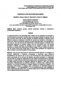
This User’s Guide is intended to assist environmental or military personnel who work with air quality measurements, regulations, and planning for the Department of Defense. Specifically, it focuses on an evaluation of three newly developed instruments for characterizing particulate matter (PM), general PM sampling recommendations, and background on PM. What is particulate matter? PM is material suspended in the air, and it can include soil, road dust, soot, smoke, and liquid droplets. PM can come directly from sources like vehicles, ships, aircraft, unpaved roads, and wood burning. Larger particles, those with a diameter larger than 2.5 µm (PM2.5), typically come from unpaved roads and windblown dust, but finer particles, Particulate Matter those smaller than PM2.5, typically come from Chemical Reactions combustion Water sources: vehicles, vapor Direct Indirect Ammonia VOCs ships, etc. PM is release formation Combustion also formed in the Emissions air when gases from burning fuels react with sunlight VOCs: volatile organic compounds and water vapor (Figure 1-1). Figure 1-1. Example of the direct release and indirect formation of particulate matter.
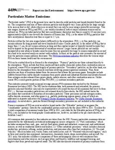
PM found in the atmosphere is made up of many compounds including soil, nitrate, sulfate, soot and organic carbon (Figure 1-2). Organic carbon includes products of incomplete combustion, such as polycyclic aromatic hydrocarbons (PAHs) and unburned fuel. The composition of PM can vary dramatically depending on the source or process condition. For example, PM from a gasoline vehicle, diesel vehicle, woodstove, or a coal-fired boiler would have dramatically different composition. 1-1
Introduction
Why is particulate matter important? Particulate matter can cause serious health effects and impair visibility. Studies over the last ten years have linked PM concentration to increased death rates, an increased incidence of asthma, and adverse cardiac effects (EPA 2000, 2002; Dockery et al. 1993; Morawska and Zhang 2002; Peters et al. 2001). More recent evidence indicates that size, surface area, and composition of PM are important factors in determining the heath effects associated with PM. For example, fine particles are thought to deposit more deeply in the lungs than larger particles (Lighty et al. 2001, Maynard and Mayndard 2002). In addition PM, especially PM from combustion sources, contains polycyclic aromatic hydrocarbons organic carbon (PAHs), which are soot reasonably anticipated nitrate to be carcinogens (NTP soil 2003), and elemental sulfate carbon, which is linked not characterized to adverse cardiac effects (Tolbert et al. 2001).
Figure 1-2. Composition of an example atmospheric particle. PM causes adverse health effects
The EPA directly regulates atmospheric levels of PM10, and it indirectly regulates PM through its visibility programs. New regulations to control PM2.5 concentrations have recently been developed. In addition to regulations on the atmospheric PM Size and composition of levels, the EPA, the states, and other agencies also regulate PM PM are important emissions from a variety of sources, such as vehicles, power factors in determining plants, aircraft, and various industries. Finally, the Occupational their heath effects Safety and Health Administration regulates PM levels in workplaces.
1-2
Introduction
Why characterize PM? Information about the size and composition of PM in the atmosphere can provide clues about its source. For example, larger particles that contain distinctive compounds, such as iron, silica, potassium, sodium, magnesium and chloride, are likely from wind-blown soil and ocean spray, but smaller particles that contain elemental and organic carbon are likely from a combustion sources. As another sample, PM from a Minuteman rocket motor contains large quantities of aluminum PM composition can compared to soil particles (Sarofim and Lighty 2003). provide information The size and composition of PM can also provide clues about about its source and its process performance. For example, an engine operating at idle health effects tends to emit smaller particles than the same engine under load. Engine operating condition also effects the portion of the particle made of organic and elemental carbon. Characterizing PM can also help understand its potential health effects (EPA 2002, HEI 2002). Research in this area is still ongoing (NRC 1988-2001), and the Health Effects Institute is a good resource for health effects information (See the resource list at the end of this section). How can newly developed instruments help characterize PM? Traditionally, determining the composition of PM was a time-consuming process. It required collecting and analyzing filters or sets of impactor substrates for composition. Although filter samples can provide detailed information about PM composition and some information about PM size, their analysis can be expensive and time consuming. The analysis methods also require a minimum amount of material, so collecting samples from the atmosphere can take many hours or even days. It is also challenging to collect sufficient PM from clean sources, such as a new gasoline vehicle. In addition, filter samples cannot provide information about process transients, when high PM emissions typically occur. This guide reviews three newly developed instruments for use in determining PM composition. •
The photoacoustic analyzer measures black carbon, also called elemental carbon, or soot (Section 2).
•
The photoelectric aerosol sensor measures particle-bound polycyclic aromatic hydrocarbons (Section 3).
•
The aerosol time-of-flight mass spectrometer measures the size and composition of individual particles (Section 4).
These instruments offer several potential benefits over traditional measurements including near real-time results, cost savings, and information about transient conditions. 1-3
Introduction
How do you collect PM samples? Designing or selecting a system for collecting PM samples can be challenging, and it is important to consider the PM source, the type of measurements you need, and the potential errors associated with the system. Section 5 of this guide discusses several common systems and offers some general guidelines. Resources General information about airborne particles: EPA’s PM information page http://www.epa.gov/oar/oaqps/regusmog/infpart.html Hinds W.C. Aerosol Technology, 2nd edition, John Wiley & Sons: New York, 1999. Kouimtzis T. (ed.) Airborne Particulate Matter, Springer Verlag: Heidelberg 1995. Maynard R.L., C.V. Howard, Particulate Matter: Properties and Effects Upon Health, Oxford: Bios Scientific, 1999. Wilson R., D. Spengler (eds). Particles in Our Air: Concentrations and Health Effects, Harvard University Press: Cambridge MA, 1996.
Health effects of particles: Health Effects Institute http://www.healtheffects.org Information about the User’s Guide: Kerry Kelly
[email protected] References EPA, PM-How Particulate Matter Affects the Way We Live & Breathe, Office of Air Quality Planning & Standards, Washington DC, 2000. EPA, Health Assessment Document for Diesel Exhaust, EPA 600/8-90/057F. National Center for Environmental Assessment, Office of Research and Development, Washington DC, 2002. Dockery, D.W., A.C. Pope, X. Xiping, J.D. Spengler, J.H. Ware, M.E. Fay, B.G. Ferris, F.E. Speizer, An Association between Air Pollution and Mortality in Six U.S. Cities; New Engl. J. Med. 1993, 329 (24) 1753-1759. HEI (Health Effects Institute) Understanding the Health Effects of Components of the Particulate Matter Mix: Progress and Next Steps, HEI Perspectives, April 2002. Lighty, J.S., J.M. Veranth, A.F. Sarofim, Combustion Aerosols: Factors Governing their Size and Composition and Implications to Human Health. Critical Review; J. Air & Waste Man. Assoc. 50 2000, 50, 1565-1618.
1-4
Introduction
Maynard A.D., R.L. Maynard, A Derived Association between Ambient Aerosol Surface Area and Excess Mortality using Historic Time Series Data, Atmos. Environ. 36 2002, 5561-5567. Morawska L., J. Zhang Combustion Sources of Particles 1. Health Relevance and Source Signatures, Chemosphere 49 (2002) 1045-1058. National Research Council (NRC), Research Priorities for Airborne Particulate Matter, volumes I – III, 1998, 1999, 2001 Washington D.C.: National Academy Press, http://www.nas.edu/nrc/ National Toxicology Program, 10th Report on Carcinogens, U.S. Department of Health and Human Services, National Toxicology program, 2003, http://ehis.niehs.nih.gov/roc Peters A.; D. Dockery, J.E. Muller, M.A. Mittleman M.A. Increased Particulate Air Pollution and the Triggering of Myocardial Infarction; Circulation, 2001, 2810-2815. Sarofim A.F., J.S. Lighty; Characterization of Particulate Emissions: Size Fractionation and Chemical Speciation, Final Report, Strategic Environmental Research and Development Program, 2003. Tolbert P.E., M. Klein, K.B. Metzger, J. Peel, W.D. Flanders, K. Todd, J.A. Mulholland, P.B. Ryan, H. Frumkin Interim Results of the Study of Particulates and Health in Atlanta (SOPHIA), J. Exposure Analy. and Env. Epid. 10 2000, 446-460.
1-5
Photoacoustic Analyzer for the measurement of soot
The photoacoustic analyzer (PA) measures soot concentration, also called black carbon or elemental carbon, in real time. The PA actually measures light absorption, which is closely correlated to soot concentration. It offers several advanThe PA measures tages over traditional filter measurements of soot including rapid turnsoot concentration around of results, study of transient conditions, large dynamic range, and in real time
What is soot?
Soot is linked to health effects
Soot comes from the combustion of jet fuel, gasoline, diesel and other fuels, and it makes up a large fraction of particulate matter in the atmosphere. Soot has been linked to adverse health effects including dysrhythmia and cardiovascular disease (Tolbert et al. 2000), and it is a significant component of diesel exhaust particulates, which are reasonably anticipated to be carcinogenic (National Toxicology Program 2003). Soot also contributes to global warming and impaired visibility (haze).
When discussing soot, it is useful to understand the terms elemental carbon (EC), soot, and black carbon (BC). If you collect particulate matter on a filter, elemental carbon is the material that remains after heating the filter to 700°C, and soot is the material remaining on a filter after extracting it with a solvent. Black carbon is the part of particulate matter that absorbs light. The PA actually measures black carbon, but it is closely correlated to elemental carbon and soot concentration. For simplicity, we’ve used the term soot throughout the guide. In general, soot isn’t regulated directly, but it is a significant component of particulate matter, especially particulate matter smaller than 2.5 ∝m in diameter (PM2.5). However, soot is regulated indirectly through standards for particulate matter, opacity, smoke, and visibility. As evidence for the health effects of particulate matter grows, regulations on particulate matter are becoming increasingly stringent. In addition, increasing emphasis is being placed on fine particulate matter. This will likely result in requirements for reduced Soot is a major soot emissions from diesel and aircraft engines. component of PM2.5
2-1
Photoacoustic Analyzer
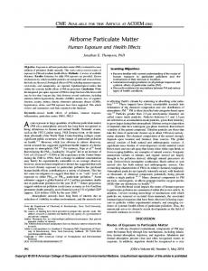
How does it work? The PA rapidly measures light absorption as particles flow through the instrument, without the need to collect particles on a filter. The light absorption correlates to soot concentration. The PA also has a large dynamic range (130 dB), making it suitable for use on a wide range of exhaust and ambient samples. Specifically, the instrument measures light absorption at a laser wavelength of 1047 nm. Soot absorbs very strongly at this wavelength, in contrast to other types of particles and gases. Sample air is pulled continuously through an acoustical waveguide, and the laser also passes through the waveguide (Figure 2-1). The laser power is modulated at the resonance frequency of the waveguide. Now when soot absorbs light, it is heated. This heat transfers very rapidly to the surrounding air, in a time that is much shorter than the period of the laser-beam modulation, so all of the heat from light absorption comes out of the particles during each acoustic cycle. Upon receiving heat, the surrounding air expands, generating a pressure disturbance (i.e. an acoustical signal) that is measured with a microphone attached to the waveguide. Since soot absorbs light throughout the entire particle volume, the light absorption measurement is also a measure of soot mass concentration. This is the reason that light absorption can be used as a measure of black carbon mass concentration.
Microphone and Surrounds
Window
Piezoelectric Transducer
Coupling Section
Coupling Section
Window
1047 nm Laser
Resonator Section
Sample Outlet
Photodetector
Sample Outlet
Figure 2-1. Schematic of the photoacoustic analyzer.
2-2
Photoacoustic Analyzer
When can you use the photoacoustic analyzer? The PA can measure soot from a variety of emission sources and ambient air. It is portable and suitable for field testing. However, there are a few practical considerations for using the PA:
The PA operates best between temperature ranges of 40. F to 100. F. Particle concentrations should range from 50 ng/m3 to 100 mg/m3. The relative humidity of a sample should not exceed 80%. The PA must remain dry and protected from the elements.
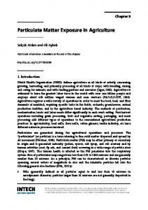
The PA has been successfully demonstrated on emissions from gasoline and diesel vehicles, jet aircraft, brick kilns, and domestic trash burning. Figure 2-2 shows an example of how well the results from the PA correspond to filter measurements of elemental carbon (not organic carbon) for a variety of aircraft ground support equipment. Organic carbon is the portion of particulate matter that volatilizes when heating a filter from 300. C to 700. C.
700
500
f(x) = 0.994x - 4.4 R^2 = 0.974
EC PA (µg/m3)
EC PA (µg/m3)
600
700 600
400 300 200
500 400 300 200
100
100
0
0 0 100 200 300 400500 600 700 EC MOUDI (µg/m3)
0
f(x) = 0.36x - 53 R^2 = 0.70
500 1000 1500 2000 2500 OC MOUDI (µg/m3 )
Figure 2-2. Comparison of PA results with filter measurements of EC and organic carbon OC.
2-3
Photoacoustic Analyzer
One of the main benefits of the PA is its ability to provide information on transient conditions, as in Figure 2-3. It shows how soot concentration varies with engine condition for a diesel Dodge Bobtail (Hill Air Force Base, 2000).
black carbon
total mass
45% load 12000
black carbon (ug/m3)
200.0
8000
150.0
23% load
6000
100.0
4000
11% load 2000 50.0
total mass (ug/m3 )
10000
34% load
0 0.0
1500
-2000
2000
2500
3000
3500
4000
4500
5000
5500
time (seconds) Figure 2-3. PA signal versus engine load.
Cost comparison Currently, the purchase price of PA assembled from premium components is approximately $36,000, including a computer. However, it is expected to decrease in the future. Analyzing filters for elemental carbon is relatively inexpensive. If you collected a set of cascade impactor filters, it would cost approximately $550 to analyze a set of nine filters. One common system for collecting filter samples is a Micro Orifice Uniform Deposit Impactor (MOUDI ), and it costs approximately $12,000. The MOUDI contains eight or ten stages, with cut points ranging from 10 µm to 56 nm. Other impactors are available, but when measuring soot remember that much of it is associated with particles less than 1 µm in diameter. So, care must be taken to ensure that particulate matter is collected in the correct size range. A qualified technician could operate the photoacoustic analyzer or a system to collect filter samples. Because the PA can produce measurements more rapidly, it offers the potential for some labor savings.
2-4
Photoacoustic Analyzer
As a rule of thumb, if you are interested in collecting a few samples, filter samples are likely to be more cost effective. However, if you need to make numerous measurements or require information on transient conditions, the PA would be more cost effective and relevant. Comarison of the PA with other methods The PA provides results more rapidly than filters
There are some differences in how soot, elemental carbon, and black carbon are measured. Elemental carbon is measured as the mass of carbon that evolves on ramping an exposed quartz filter sample form a lower to upper temperature range, typically 500. C to 700. C. In practice, the most reproducible elemental carbon concentration is when 47-mm filters are loaded with 1 mg of material. Filters are exposed, shipped to the laboratory, put in the analysis queue, and eventually analyzed, perhaps months after they were exposed, so the data acquisition rate is often slow. The dynamic range is limited by the need to obtain a loading of about 1 mg/sample on the filter. On the other hand, if you are interested in the size-segregated distribution of elemental carbon, cascade impactors, such as a MOUDI, are more appropriate.
Black carbon is measured by light absorption, and this correlates to soot concentration. The absorption efficiency of soot is much larger than the efficiency of other atmospheric aerosols. Soot aerosols are small enough that the light is absorbed throughout the aerosol volume, so that aerosol light absorption is proportional to the mass concentration of light-absorbing aerosols. The proportionality between aerosol light absorption and soot mass concentration is typically obtained from the linear rgression coefficient against elemental carbon. In this sense, soot should be equivalent to elemental carbon in source-profile measurements. Light absorption measurements are commonly made by filter-based methods in instruments such as aethalometers (Hansen et al. 1984) and particle soot absorption photometers (PSAP). In these methods, a quartz filter is exposed to aerosol, and the attenuation of light through the filter is monitored over time. The filter is a multiple scattering substrate so that the reduction in the transmitted light is proportional to the aerosol absorption cross section. The PSAP calibration requires simultaneous measurement of aerosol scattering coefficient with a nephelometer because a fraction of scattering is subtracted from the apparent light absorption from the filter attenuation (Bond et al. 1999). For very black aerosols, such as those from diesel engines or coal combustors, the multiple scattering character of the filter reduces with aerosol load. Consequently, the reported black carbon concentration can be incorrect by a factor of two, depending on the time history of filter loading. These filter-based methods suffer from low dynamic range because the black carbon concentration is proportional to filter attenuation only 2-5
Photoacoustic Analyzer
for light filter loads. This limitation reduces the effectiveness of the filter method for source profile measurements of high emitters, as filter Filter-based changes are needed often. Secondary dilution can extend the upper instruments work limit, although quantification of the dilution ratio increases measurement best for low soot errors. Filter-based measurements perform best with low concentrations concentrations of black carbon, such as in ambient applications. The practical flow rates for these instruments range from 1 to 6 l/min , and the flow rate must be accurately determined to quantify filter exposure during a particular time interval. Rapid changes in the relative humidity (over seconds to many minutes) can cause unsatisfactory measurements by these methods. The PA also measures aerosol light absorption and can be calibrated to read soot concentration (Arnott et al. 1999, 2000). The aerosol light absorption measurement can be verified independently with measurements of light-absorbing gases, such as NO2 at known concentrations and for visible wavelengths. Aerosol light absorption is measured in situ, no filters are needed, and flow rates are only important to ensure that aerosols are not deposited in the instrument or sample lines before they are measured. Since the PA’s microphones have such a wide dynamic range, the black carbon measurements have the same dynamic range, e.g. a factor of 106. The PA can quantify a The PA can equally be used in pristine ambient locations or in large range of soot source profile measurements for high emitters. There are no concentrations and is less filter artifacts. Relative humidity influence is likely not sensitive to humidity important when it is below 80%.
Vision for use DoD users should look to the PA for all of their black carbon mass concentration needs. It is useful in doing ambient measurements at fixed locations such as in air quality measurements at military bases. It is useful in profiling sources at these bases, particularly when dynamometers and constant-volume samplers are used. It is also useful in instrumented vehicles to measure black carbon issuing from the vehicle it is on, or as a function of time and space.
2-6
Photoacoustic Analyzer
Resources Website for the photoacoustic analyzer: http://photoacoustic.dri.edu For more information about the photoacoustic analyzer, Dr. Pat Arnott:
[email protected] For general information or information about this User’s Guide, Kerry Kelly:
[email protected] References Arnott W.P., H. Moosmuller, J.W. Walker, Nitrogen-Dioxide and Kerosene-Flame Soot Calibration of Photoacoustic Instruments for Measurement of Light Absorption by Aerosols. Rev. Sci. Instrum. 71 2000 4545-4552. Arnott W. P., H. Moosmüller, C. F. Rogers, T. Jin, R. Bruch, Photoacoustic spectrometer for measuring light absorption by aerosols: Instrument description. Atmospheric Environment 33 1999 2845-2852. Bond T.C., T L. Anderson, D. Campbell, Calibration and Intercomparison of Filter-Based Measurements of Visible Light Absorption by Aerosols. Aerosol Science and Technology 30(6) 1999 582-600. Hansen, A.D.A., H. Rosen, T. Novakov (1984). The Aethalometer - An Instrument for the Real-Time Measurement of Optical Absorption by Aerosol Particles. Science of the Total Environment 36 1999 191196. NTP (National Toxicology Program 10th Report on Carcinogens, U.S. Department of Health and Human Services, National Toxicology Program, 2003, http://ehis.niehs.nih.gov/roc/ Tolbert P.E., M. Klein, K.B. Metzger, J. Peel, W.D. Flanders, K. Todd, J.A. Mulholland, P.B. Ryan, H. Frumkin Interim Results of the Study of Particulates and Health in Atlanta (SOPHIA), J. Exposure Analy. and Env. Epid.10 2000 446-460.
2-7
Photoelectric Aerosol Sensor for measuring particle-bound polycyclic aromatic hydrocarbon concentration
The photoelectric aerosol sensor (PAS) qualitatively measures the concentration of particlebound polycyclic aromatic hydrocarbons (PAHs). It gives a relative measure of particle-bound PAH concentration or, with appropriate calibration, a more accurate measure of PAHs. The PAS may provide a qualitative measure of total PAS measures PAH concentrations more rapidly and cost effectively than traditional particle-bound measurements, such as filter extraction and subsequent GC/MS analysis. PAHs However, the PAS cannot provide concentrations of individual PAHs, and developing a calibration curve for each instrument and source can be expensive and time consuming. What are PAHs?
PAHs have negative health effects
PAHs are a complex group of hundreds of chemicals that are formed during the incomplete burning of fuels, such as oil, wood, gasoline, diesel and jet fuel, and garbage. They are commonly found in vehicle exhaust and cigarette and wood smoke. Figure 3-1 gives the structure of some PAHs. PAHs as a group are reasonably anticipated to be carcinogenic (NTP 2003), and a few individual PAHs, such as benz[a]anthracene and benzo[a]pyrene, are probably carcinogenic (IARC 2003).
Naphthalene
Pyrene
Benzo[a]pyrene
Indeno[1,2,3cd]pyrene
Benz[a]anthracene
Figure 3-1. Example structure of a few PAHs.
3-1
Photoelectric Aerosol Sensor
In the atmosphere or in exhaust from a combustion source, PAHs can be found on particles or as a vapor. Heavier molecular weight (MW) PAHs tend to be found on particles, whereas lighter MW PAHs are more typically found as vapors. The phase of the PAHs will also depend on their source and its operating condition. For example, diesel exhaust tends to contain more particlebound PAHs at higher engine load than at idle conditions. A few PAHs are regulated directly in the United States, and other countries regulate individual PAHs or classes of PAHs. The EPA regulates emissions of one PAH, naphthalene, as a hazardous air pollutant, and seven PAHs are included on EPA’s list of urban air toxics, which may be regulated in the future. PAHs can be Particle-bound PAHs are regulated indirectly through standards for found in vapor or particulate matter, opacity, smoke, and visibility. Typically, PAHs make up on particles a small fraction of particle mass. How does it work? Figure 3-2 shows a schematic of the PAS, and additional instrument details can be found in EPA (1997) and Burtscher (1992). Briefly, samples flow continuously into the PAS and through the eximer-lamp ionization region, where particle-bound PAH molecules are ionized and loose an electron. The photon energy of the lamp is chosen so that gas-phase molecules are not ionized. The negatively charged particles collect on a filter where charge is measured with an electrometer. The charge is integrated over time to give the photoelectric current (in femto- or picoamps). This current should be proportional to the PAH loading on a particle. Three versions of the PAS are available commercially, but they all have similar operating principles.
Ionization Chamber
Flow Inlet Charge Separation
Filter Flow Outlet
Mass Flow Meter
Figure 3-2. Schematic of the PAS.
3-2
Photoelectric Aersol Sensor
The PAS was originally calibrated to fifteen individual PAHs (called For a more accurate the Siegmann sum) from several sources, with a universal conversion measure of PAHs, 3 -1 factor of 1-3 µg/m picoamp (Wilson and Barbour 1994, Wilson et al. calibrate each PAS 1991, EPA 1999). Because PAHs are such a complex mix of vapor and for each source type particle-phase compounds, the PAS responds differently to each type of source, and calibration factors can vary widely (Figures 3-3 and 3-4). Without an appropriate calibration curve, the PAS will only give you a relative measure of particle-bound PAH levels. Independent comparisons of the PAS and filter measurements are limited (Chuang et al. 1999, Chetwittayachan et al. 2002, Tang et al. 2001, Arnott et al. in progress), and the results are contradictory. Figures 3-3 and 3-4 compare PAS results with filter measurements for military vehicles and aircraft, and they show how the PAS response varies for different sources. The PAS results correlate reasonably well with filter measurements for military vehicles (R2 = 0.762) and better for military aircraft (R2=0.99), but the aircraft correlation is heavily weighted by one data point. The response of each PAS instrument varies for each source type, so a calibration curve for each instrument should be developed for each source. For vehicle and aircraft emissions, it is also interesting to note that the PAS correlates well with soot concentration (Baltensperger et al. 2001, Matter et al. 1999, Arnott et al. in progress).
10000 Gasoline, diesel, and JP-8 fueled vehicles y = 6.2x -18 (R2 = 0.762)
PAS (femtoamp)
8000
6000
4000
2000
0
0
200
400
600
800
1000
1200
1400
1600
Denuder filter Siegmann sum of PAHs (ng/m3)
Figure 3-3. Correlation of PAS readings with denuder filter measurements of particle-bound PAHs for several vehicles.
3-3
Photoelectic Aerosol Sensor
4500
Aircraft
4000
y = 2.1x +299 (R2 = 0.99) 3500
PAS (femtoamp)
3000 2500 2000 1500 1000 500 0 0
200
400
600
800
1000
1200
1400
1600
1800
2000
Denuder filter Siegmann sum PAH (ng/m3)
Figure 3-4. Correlation of PAS readings with denuder filter measurements of particle-bound PAHs for aircraft.
When can you use the photoelectric aerosol sensor? The PAS can qualitatively measure PAH emissions from a variety of emission sources and ambient air. For source sampling, there are a few practical considerations: •
•
PAS results correlate somewhat with filter measurements
Maintain PAS readings below 50 picoamps. Exposing the PAS to high levels of water vapor or source emissions, such as diesel exhaust, will cause erratic results. Measurements of anything other that ambient air requires dilution with dry, particle free air. Keep the PAS inlet temperature constant because PAS results vary with inlet temperature. Studies at the University of Utah found a temperature of approximately 250-300°F to be reduce erratic negative signals. The PAS manufacturers sell a dilution/heated inlet system. Alternatively, you can wrap the inlet line with heating tape.
3-4
Photoelectric Aerosol Sensor
• • •
The instrument itself should operate at temperatures between 0°F and 105°F. Depending on the source, the PAS can detect a minimum PAH concentration of 10 ng/m3. The PAS must remain dry and protected from the elements.
Cost comparison Chemical analysis of PAHs from filter samples is expensive. For example, analyzing nine stages of a cascade impactor for PAHs costs approximately $4,700 and analyzing a denuder/filter system costs approximately $1,500 (if the three components are analyzed separately). These costs do not include the labor costs associated with collecting the samples or the costs of the sampling devices. One type of cascade impactor, a micro-orifice uniform deposit impactor (MOUDI), costs approximately $12,000 for the entire complete setup and a denuder/filter system costs approximately $2,000 – 4,000 (depending on configuration). Furthermore, chemical analyses for PAHs are time consuming; it typically takes several months to receive the analytical results. Alternatively, the PAS collects data in real time, and the data can be downloaded and analyzed in the matter of days. The PAS 2000 costs approximately $15,000 (2003 price). Comparison of the PAS with other methods There are two basic methods for measuring particle-bound PAHs. The first involves collecting samples on a filter followed by chemical analysis, and the other is the PAS. Filter samples are commonly collected on cascade impactors, such as MOUDIs, or on a denuder/filter system. The MOUDI contains eight to ten stages plus an after filter, and each stage contains a filter. A denuder/filter system contains three parts, a resin-coated denuder that absorbs vapor-phase PAHs, a filter that collects particles, and a cartridge to collect excess particles and vapor from the filter and denuder. The next step in chemical analysis is extracting the filters or denuder/filter components with a solvent, such as hexane. The extract may be concentrated to improve the detection of low-concentration PAHs, and impurities may be removed. Next, the extract is analyzed by an advanced analytical method, such as gas chromatography/mass spectrometry. The entire process of PAH analysis is PAH analysis challenging because of the low concentrations of PAHs, the potential is challenging interference from the complex mixtures of chemicals in which PAHs are found, and the reaction of compounds during sampling and storage. Traditional filter measurements and denuder/filter systems provide some information that cannot be obtained with the PAS. For example, the traditional analyses measure concentrations of individual PAHs, instead of the total particle-bound PAH content as measured by the PAS. In addition, the denuder/filter system provides information on vapor- and particle-
3-5
Photoelectric Aerosol Sensor
phase concentrations of individual PAHs. Finally, substrates collected on a MOUDI or other cascade impactor can give information on the size of particles on which PAHs are found. A filter or denuder/filter system requires a minimum amount of material for analysis, but excessive amounts of sample may cause artifacts. If a Chemical analysis filter is properly prepared, a trained graduate student or technician can provides more collect a filter or impactor sample. However, it is difficult to determine if information there is sufficient sample for PAH analysis before the sampling is complete. After sampling is complete, a small section of the filter can be analyzed for organic carbon content, which provides an indication of the PAH loading. A further complication for cascade impactors, such as a MOUDI, is that mass loading will vary by impactor stage. Operation of the denuder/filter system is delicate and requires an experienced scientist. For example, an individual must ensure that the flow is sufficiently high to prevent very small particles from depositing on the denuder portion. However, if one overloads the denuder, the flow will drop, causing particle deposition and erroneous results. For ambient samples, collecting sufficient material may require several days of sampling, and for source samples it may require from tens of minutes to hours. The PAS is relatively easy to operate, and it provides results rapidly. However, it is not as accurate as the chemical analysis methods, and it provides less detailed information. A technician or student could operate the PAS. The PAS can measure a large range of PAH concentrations, and it is sensitive enough to detect ambient levels of PAHs down to 10 ng/m3. With dilution the PAS can measure emissions from combustion sources, such as diesel engines. However, care must be taken not to expose the PAS directly to undiluted exhaust from a source like a diesel engine, which will cause erratic signals. Because the PAS records PAH concentrations rapidly (at intervals less than 10 seconds), it is particularly useful for studying transient conditions, such as process start up or engine acceleration. On the other hand, filter analyses require sufficient time for material to deposit on the substrates, and these analyses are not sensitive enough to provide information on transient conditions. The PAS does have a few disadvantages: is not as accurate as the chemical analysis methods, and each instrument should be calibrated for each source type, which is expensive and time consuming. Furthermore, the PAS provides the total The PAS provides concentration of particle-bound PAHs; it cannot provide the rapid results concentrations of individual PAHs or information about vapor-phase PAHs.
3-6
Photoelectric Aerosol Sensor
PAH detection and analysis is challenging, and there are significant tradeoffs between chemical analysis methods and the PAS. Chemical analysis provides accurate concentrations of individual PAHs. They can provide the size of particles on which PAHs are associated and which PAHs are found in vapor and particle phases. However, chemical analysis methods are expensive, time consuming, and subject to artifacts. The PAS rapidly provides a relative measure of total PAH concentrations and can provide information on transient conditions. However, more accurate results could be obtained by calibrating each PAS for each source. Chemical analysis is more accurate and Vision for use provides more data but is more expensive and The PAS is a good choice when a relative measure of particle-bound time consuming PAHs is desired or when transient conditions are studied. For example, it would be useful for the preliminary evaluation of a control device, for screening sources for further analysis, or for studying transient conditions. The PAS is a relatively new instrument, and with additional study and independent calibration it may produce more valuable results. Chemical analysis methods are a good choice if you want quantitative PAH concentrations, accurate concentrations of individual PAHs, or information about the phase distribution of PAHs. Resources Website for the photoelectric aerosol sensor: http://www.ecochem.biz/PAH/PAS2000.htm For general information or information about this User’s Guide, Kerry Kelly:
[email protected]
References Arnott et al., Evaluation of 1047 nm Photoacoustic Instruments and Photoelectric Aerosol Sensors in Source-Sampling of Black Carbon Aerosol and Particle-Bound PAH’s from Gasoline and Diesel Powered Vehicles, in progress. Baltensperger, U. E. Weingartner, H. Burtscher, J. Keskienen, Dynamic Mass and Surface Area Measurements. In: P.A. Baron and K. Willeke (eds.) Aerosol Measurement 2001 New York:Wiley, pp. 387-418. Burtscher, H. Measurement and Characteristics of Combustion Aerosols with Special Consideration of Photoelectric Charging and Charging by Flame Ions; J. Aerosol Sci. 1992, 23 (6) 549-595.
3-7
Photoelectric Aerosol Sensor
Chetwittayachan T., D. Shimazaki, K. Yamamoto, A comparison of temporal variation of particle-bound polycyclic aromatic hydrocarbons (pPAHs) concentration in different urban environments: Tokyo, Japan, and Bangkok, Thailand, Atmos. Environ. 36 2002 2027-2037. Chuang, J.C, P.J. Callahan, C.W. Lyu, N.K. Wilson, Polycyclic aromatic hydrocarbon exposures of children in low-income families, J. Exposure Analysis and Environ. Epid. 2 1999 85-98. EPA. Field and Laboratory Analyses of a Real-Time PAH Analyzer, EPA/600/R-97/034; EPA Office of Research and Development, 1997. International Agency for Research on Cancer, IARC Monographs, 2003, vol. 1-82 http:// monographs.iarc.fr/monoeval/crthall.html Matter U., H.C. Siegmann, H. Burtscher, Dynamic Field Measurements of Submicron Particles from Diesel Engines, Environ. Sci. Technol. 33 1999 1946-1952. National Toxicology Program, 10th Report on Carcinogens, U.S. Department of Health and Human Services, National Toxicology program 2003, http://ehis.niehs.nih.gov/roc Tang, S., R. Johnson, T. Lanni, W. Webster, T. Tagliaferro, H. Munn, C. Barnes, D. Barnes, K. Newkirck, D. Rivenburgh, D. Guerrieri, Monitoring of PM-bound polycyclic aromatic hydrocarbons from diesel vehicles by photoelectric aerosol sensor (PAS), Automotive Emissions Laboratory, New York Department of Environmental Conservation, March 22, 2001. Wilson N.K., Barbour, R,K., Evaluation of a real-time monitor for fine particle-bound PAH in air, Polycyclic Aromatic Compounds 5 1994 167-174. Wilson N.K., Chuang, J.C., MR. Sampling polycyclic aromatic hydrocarbons and related semivolatile organic compounds in indoor air. Indoor Air 4 1991 513-512.
3-8
Aerosol Time-of-Flight Mass Spectrometer for measuring individual particle size and composition
The aerosol time-of-flight mass spectrometer (ATOFMS) determines size and composition of single particles in near real-time. It is available commercially from TSI Inc. (Model 3800). The ATOFMS is a powerful tool because it provides associations between compounds within single particles, and this information can be used to identify a particle’s source. The ATOFMS also provides PM composition The ATOFMS for transient conditions, when bulk techniques, such as filters, cannot. determines a particle’s size and composition Why is understanding the size and composition of individual particles useful? Studies over the last ten years have linked particulate matter (PM) concentration to adverse health effects, and more recent evidence indicates that size, surface area, and composition of PM are important factors in determining the heath effects associated with PM. For example, certain metals found in PM, such as iron, nickel and vanadium have been linked to adverse effects on the lung. The composition of individual particles can also provide insight into particle formation and chemistry, and it can help identify the source of a particle by its chemical composition, i.e., fingerprint. For A particle’s size example, it can provide fingerprints for specific sources, such as exploand composition sives, diesel engines, and biological aerosols. can provide clues about its source How does it work? and health effects Figure 4-1 shows a schematic of the ATOFMS. The ATOFMS consists of three regions: • • •
Particle sampling region Particle sizing region Mass spectrometry region
In the commercially available ATOFMS, particles are introduced into the particle-sampling region under atmospheric pressure through a converging nozzle where they are accelerated according to their aerodynamic size. Smaller particles reach a higher terminal velocity than larger particles. The accelerated particle next enters the particle sizing region, where particle velocity is measured by recording the transit time for the particle to pass between two continuous-wave laser beams 4-1
ATOFMS
positioned a fix distance apart. Particle size is then determined by comparing the velocity of the particle to a calibration curve, which is obtained using particles of known size. Finally, the particle reaches the mass spectrometry region. Using the known speed of the particle, a Nd:YAG laser at 266 nm is fired at the exact time the particle reaches the center of the ion source in the mass spectrometer. This laser pulse desorbs and ionizes the compounds making up the particle. The ions formed in this process are analyzed by a bipolar time-of-flight mass spectrometer. The resulting mass spectra are then used to determine the chemical composition of the particle.
Particles
Ellipsoidal Mirrors
Reflectron
PMTs
Diode Lasers (532 nm)
Reflectron
+ ions
- ions
Nd:YAG Laser (266 nm)
Detectors
Figure 4-1. Schematic of the ATOFMS.
The operation of the ATOFMS is based on two established methods: • •
Aerodynamic particle sizing Time-of-Flight Mass Spectrometry (TOFMS)
4-2
ATOFMS
What is aerodynamic sizing? Aerodynamic particle sizing is based on the inertia of particles. When a gas expands, it is accelerated. Particles suspended in the gas are also accelerated, but the extent of the acceleration depends on their aerodynamic diameter. The aerodynamic diameter is defined as the diameter of a unit density (density = 1 g/cm3) sphere that has the same settling velocity as the particle (TSI, 2002). Not only the physical diameter but also the shape and density of the particle are taken into account. The smaller a particle, the higher the acceleration and therefore the terminal velocity it reaches. This velocity can be determined by measuring the time it takes the particle to travel a known distance. Usually this transit time is measured using a split laser beam or with beams from two lasers (which is used in the 3800 ATOFMS). The scattered light is collected with a detector and the signals are used to start and stop a clock registering the transit time. Transforming the transit time into size is done by calibrating the instrument with a number of particles of known size to create a calibration curve. This calibration curve is then used to determine the size of the unknown sample (TSI, 2002). What is time-of-flight mass spectrometry? There are many types of mass spectrometry (MS). A common component of all MS systems is that ions are separated based on their mass-to-charge ratio (m/z). The first mass spectrometry instruments used a magnetic field to separate ions. Later instruments used magnetic and electric fields. Other common methods include those that use quadrupole mass filter, quadrupole ion traps, ion traps in static magnetic fields (Fourier transform mass spectrometry), and time-of-flight (TOF-MS) measurements. Each method has its advantages and disadvantages depending on the application. FTMS, for example, can provide extremely high mass resolution. Quadrupole and quadrupole ion trap instruments can be very small. TOF instruments offer the advantage of not being a scanning method, that is, you get a complete spectrum for each ionization event. As the name suggests, TOFMS accelerates ions to a specific kinetic energy and measures the ions’ time-of-flight between a distinct starting point (often the ionization event) and the arrival at the detector. The ions arrival times are correlated with their mass-to-charge ratios, with smaller m/z ions arriving before larger m/z ions. Upon calibration of the mass spectrometer, the measured ion transit times can be converted to the corresponding mass-to-charge ratios, which are related to the chemical components in the original particles. The most common start event is the pulse of the desorption/ionization (D/I) laser. This event starts the data logging; the ion current from the detector is recorded over time and creates the mass spectrum. Ions created in the ion source are accelerated into the flight tube by a potential that is usually created by two source plates. As all ions have the same energy, the potential where they were formed, the acceleration (and therefore the velocity they reach at the end of the ion source) depends only on their mass-tocharge ratio: 4-3
ATOFMS
=
eV
v
=
mv 2 2z 2 zeV m
where: eV is the potential energy of the ion, m/z is the mass-to-charge ratio, and v is velocity.
This equation shows that ions with a small m/z are accelerated to a higher terminal velocity than ions with a large m/z. After the initial acceleration step, the ions enter the flight tube, also known as the field free region or drift region. This part of the mass spectrometer is held at a constant potential (hence the name field free region) and the ions drift at the velocity they achieved from their acceleration in the ion source (drift region). During this time, ions separate based on their velocity and therefore their m/z. At the end of the flight tube, they hit a detector and create an ion current that is measured and recorded to create the mass spectrum.
Figure 4-2. Time-of-flight mass spectrometry principles.
4-4
ATOFMS
During the desorption/ionization event, ions can obtain additional kinetic energy from the explosion during desorption. Some ions travel in the direction they are accelerated in, while other ions travel in the opposite direction. This leads to a spread in energy for ions with the same m/z. As a result of this, ions with the same m/z end up with different velocities, which results in peak broadening due to different arrival times at the detector (low mass resolution). One way to correct this resolution issue is to use a reflectron or ion-mirror. The reflectron consists of a number of parallel, concentric electrodes to which a potential ramp is applied. The most common type of reflectron is the linear reflectron, which shows a linear potential increase. As the ions enter the reflectron, they slow down, stop, turn around, and are accelerated out of the reflectron again. Ions with higher energies penetrate the reflectron more deeply than ions with a smaller energies. Faster ions (high energy ions) therefore travel deeper into the reflectron than slower ions of the same m/z and spend more time in the reflectron. With the voltages set correctly, all ions of the same m/z are focused at the same arrival time on the detector surface (see Figure 4-3).
Figure 4-3. The reflectron focuses ions with different velocities/energies in time onto the detector.
When can you use the ATOFMS? The ATOFMS has a few practical considerations: • • • • •
The commercially available version of the ATOFMS detects PM in the size ranging from 300 nm to 3 µm. It is possible to modify the ATOFMS with an aerodynamic lens to detect smaller sized particles, as small as 50 nm. The ATOFMS is mobile and frequently operates in the field. However after moving, the instrument’s lasers may need alignment. In addition, it weighs approximately 800 lbs. For power, the ATOFMS requires 20 A of 220-240 VAC and 20 A of 110-120 VAC. The instrument itself should operate at temperatures between 50°F and 95°F. The ATOFMS must remain dry and protected from the elements. 4-5
ATOFMS
Cost comparison The ATOFMS is relatively expensive compared to an individual bulk sample. It currently costs $360,000. However, it can provide information that is not available through any other methods. Costs for the analysis of bulk samples (i.e., filters) range from a few dollars to a few thousand dollars per filter. If The ATOFMS is you are collecting and analyzing many bulk samples, the analysis costs more expensive than can quickly run into the range of the ATOFMS’s price. For the bulk samples, but it ATOFMS, a trained scientist must collect the samples and interpret the can provide more results. By comparison, bulk samples can be collected by a technician data and sent away for analysis. Comparison of the ATOFMS with other methods There are two basic methods for measuring particle size and concentration. The first involves single-particle mass spectrometry and the other involves collecting bulk samples on a set of cascade impactors or filters followed by chemical analysis. Single-particle mass spectrometry A number of mass spectrometer designs have been developed for aerosol analysis in the past decade. The other alternative single-particle methods (i.e. PALMS, RSMS) either provide limited size information or must step through discrete particle sizes. The ATOFMS is the only commercially available single particle MS and the system offers the highest size resolution and real-time analysis of particle size and composition across a range of sizes from 50 nm up to 78 µm. A complementary alternative to single particle mass spectrometry is aerosol mass spectrometry (AMS), a system developed by Aerodyne, which collects the average composition of an ensemble of many particles. This technique can be more quantitative than single-particle instruments but does not provide any information on the chemical associations within individual particles (or mixing state). Single-particle mass spectrometry is the only method to provide the composition of single particles, and the ATOFMS was the first commercially available instrument. When comparing ATOFMS to bulk methods, the advantages and disadvantages are similar to other single-particle mass spectrometry methods. The key advantage is that ATOFMS can be used to determine associations between species within individual particles. These associations can be linked with sources, making source apportionment much more straightforward than bulk measurements, which scramble the chemical information from multiple sources collected over some long sampling interval. 4-6
ATOFMS
Also, the associations are key to understanding the health effects of these particles, as well as their optical properties, which are important in climate change issues. It is impossible to get these associations with bulk techniques, which mix the chemical signatures of thousands of particles together. Furthermore, the ATOFMS can acquire information on much shorter timescales than bulk measurements, which must sample for many hours in order to collect enough material for analysis, precluding the observation of short-term changes in PM composition. Experience is needed The key disadvantage of the ATOFMS is its cost and the learning curve to operate the required to interpret the spectra. However, the commercial system is ATOFMS and internow being successfully used by a broader set of users, and more pret its results information is becoming available on particle types and analysis methods. The commercial ATOFMS is the only available method that can continuously measure single particle size and composition. New ATOFMS systems are currently being designed which will reduce the size, weight, and power requirements and the overall cost of the system. This will make them more widely available. Bulk samples Bulk PM samples are commonly collected on cascade impactors, such as a micro-orifice uniform deposit impactors (MOUDIs) or Andersen impactors. The impactors contain eight to ten stages plus an after filter, and each stage contains a filter. Depending on the analysis method, the next step may be extracting the filters a solvent, such as hexane. The extract can be concentrated to improve the detection of low-concentration compounds, and impurities may be removed. Next, the extract or the filter is analyzed by an advanced analytical method, such as gas chromatography, mass spectrometry, x-ray fluorescence, or instrumental neutron activation analysis. Some compounds are present in low concentrations, so analysis can be challenging. Furthermore, evaporation, condensation, and reaction of compounds during sampling, extraction, and storage can also cause artifacts. Chemical analysis of filter samples for some compounds is challenging
Cascade impactor samples provide PM within a certain size range, such as 0.05 µm to 0.1 µm, so the PM sizing is not as precise as the ATOFMS. Furthermore, a filter requires a minimum amount of material for analysis; depending on the source, sample collection may take hours or even days, so any transient differences in PM composition will be lost in the bulk sample. It is also difficult to determine if there is sufficient sample for analysis before the sampling is complete. A further complication for cascade impactors is that material loading will vary by impactor stage.
4-7
ATOFMS
The key advantage of a filter/impactor samples is that they are less expensive than ATOFMS measurements or other single-particle mass spectrometry methods. Furthermore, a trained technician can collect samples instead of an experienced scientist. However, these bulk measurements lack the ability to provide rapid results, information about transient conditions, and associations Bulk samples cannot between species in individual particles. provide data on transient conditions Vision for Use The most obvious applications for DoD users would be source apportionment (as demonstrated in SERDP project CP1106) and detection of signature compounds, including biowarfare detection. Biological particles can easily be discriminated from other atmospheric particles on a continuous basis. These instruments conceivably could detect individual bacteria and discriminate between them and particles from other sources. ATOFMS could acquire this information continuously so the particles of concern could be detected instantaneously for early warning. This has serious defense ramifications. Resources For more information about time-of-flight mass spectrometry: Cotter, R.J. The new time-of-flight mass spectrometry. Analy. Chem.71(13) 1999 445A-451A. Cotter, R. J. Time-of-flight mass spectrometry, instrumentation and applications in biological research. J. Liq. Chrom. & Rel. Technol. 21(6) 1998 903-914. Mamyrin, B.A., V.I. Karataev, D.V. Shmikk, V.A. Zagulin, Sov. Phys. JETP 1973 pp. 37, 45.
For additional information about the ATOFMS: ATOFMS Web site http://www.tsi.com/particle/products/massspec/3800.shtml Galli, M., S.A. Guazzotti, K.A. Prather, Improved Lower Particle Size Limit for Aerosol Time-of-Flight Mass Spectrometry. Aerosol Sci. & Technol. 34(4) 2001 381-385. Gross, D.S., M.E. Galli, P.J. Silva, S.H. Wood, D.Y. Liu, K.A. Prather, Single Particle Characterization of Automobile and Diesel Truck Emissions in the Caldecott Tunnel. Aerosol Sci. & Technol. 32(2) 2000 152-163. Middlebrook, A.M.; D.M. Murphy, S.H. Lee, et al. A Comparison of Particle Mass Spectrometers during the 1999 Atlanta Supersite Project. J. Geophys. Res. [Atmospheres] 2003 108(D7).
4-8
Photoacoustic Analyzer
Noble, C.A, K.A. Prather, Real-Time Single Particle Mass spectrometry: A Historical Review of a Quarter Century of the Chemical Analysis of Aerosols. Mass Spec. Rev. 19(4) 2000 248-274. Noble, C.A., K.A. Prather, Aerosol Time-of-Flight Mass Spectrometry. 353-376.
Analy. Chem. Aerosols 1999
Suess D.T., K.A. Prather, Mass Spectrometry of Aerosols, Chem. Rev. 99 1999 3007-3035. Wexler, A., K.A. Prather, Introduction: Online Single Particle Analysis. Aerosol Sci.& Technol. 2000 33(1-2) 1-2.
ATOFMS Applications: Guazzotti, S. A., J.R. Whiteaker, D. Suess, K.R. Coffee, K.A. Prather, Real-Time Measurements of the Chemical Composition of Size-Resolved Particles during a Santa Ana Wind Episode, California USA. Atmos. Environ. 35(19) 2001 3229-3240. Liu, D.Y., D. Rutherford, M. Kinsey, K.A. Prather, Real-Time Monitoring of Pyrotechnically Derived Aerosol Particles in the Troposphere. Analy. Chem. 1997 69(10), 1808-1814. Liu, D.Y., R.J. Wenzel, K.A. Prather, Aerosol Time-of-Flight Mass Spectrometry during the Atlanta Supersite Experiment: 1. Measurements. J. Geophys. Res. [Atmospheres] 2003 108(D7). Prather, K., C. Noble, D. Liu, P.J. Silva, Single Particle Analysis of Transient Variations occurring in Atmospheric Aerosols. J. Aerosol Sci. 1998 29(Suppl. 1, Pt. 2), S1185-S1186. Silva, P.J, R.A. Carlin, K.A. Prather, Single Particle Analysis of Suspended Soil Dust from Southern California. Atmos. Environ. 34(11) 2000 1811-1820. Suess, D.T., K.A. Prather, Reproducibility of Single Pparticle Chemical Composition during a Heavy Duty Diesel Truck Dynamometer Study. Aerosol Sci. & Technol. 36(12) 2002 1139-1141. Wenzel, R.J., D.Y. Liu, E.S. Edgerton, K.A. Prather, Aerosol Time-of-Flight Mass Spectrometry during the Atlanta Supersite Experiment: 2. Scaling Procedures. J. Geophys. Res. [Atmospheres] 2003 108(D7). Whiteaker, J.R., K.A. Prather, K.A. Detection of Pesticide Residues on Individual Particles. Analy. Chem.75(1) 2003 49-56.
For general information or information about this User’s Guide, Kerry Kelly:
[email protected] References Hinds, W.C. Aerosol Technology, 1 ed.; John Wiley & Sons: New York 1982. TSI, Model 3800 Aerosol Time-of-Flight Mass Spectrometer Instruction Manual, P/N 1930036. TSI Incorporated 2002.
4-9
Dilution and Sampling Design and selection of a dilution/sampling system is one of the most challenging problems associated with characterizing particulate matter (PM). This section highlights some important things to consider when selecting a dilution/sampling system, and it is divided into: • • • • • • •
Sample types Types of measurements Effects of dilution systems Dilution gas General recommendations for dilution/sampling systems Common systems Rules of thumb
What type of samples will you be collecting, ambient or source?
Sample types If you are collecting a PM sample, the first question to ask is whether you’ll be collecting a source sample or an ambient sample. For sources, your sample intake will be located directly in the exhaust, i.e., in the tailpipe of a vehicle. For ambient samples, your intake is located out of the direct exhaust of any sources. Typically, ambient samples experience much lower levels of PM than source sampling. This guide focuses on source sampling. For guidance on ambient sampling see the list of resources at the end of this section. For source sampling, the instruments discussed in this guide (and most particle instruments) require dilution in order operate within their required ranges. Dilution with dry gas also may approximate the processes that occur naturally after exhaust particles and gases mix with ambient air. It also reduces the humidity of the sample gas and water condensation in the sample lines. Figure 5-1 illustrates a generic dilution system. In most systems, Dry, clean exhaust from a source is pulled dilution air into a chamber, where it mixes with dry, clean dilution air; this mixture then flows into a Source Mixing Sampling Chamber sampling chamber, where particle Diesel, gasoline, instruments are located. jet engine, etc. Figure 5-1. Generic dilution and sampling system.
5-1
Dilution and Sampling
Types of measurements Currently, particle mass is a regulated pollutant, but interest is growing in particle number and composition. Your design and selection of a dilution/sampling system will depend on what you’d like to measure. Extensive research on the effects of dilution systems on PM shows that Do you want to dilution/sampling systems typically affect particle counts for particles less measure PM than 50 nm in diameter (Maricq et al. 2001; Abdul-Khalek et al. 1999; mass, number, or Kittelson et al. 1999, 2000, 2002; Shi and Harrison 1999). There are two composition? main effects. Rapid cooling can cause nucleation of droplets of sulfuric acid or hydrocarbons. These are usually in the size range of 1 nm and produce an artificially large number count. Alternatively if large numbers of particles exist in the nucleation size range, they will agglomerate with larger particles if the dilution rate is not fast enough and the number count will be artificially low. If the systems are clean and operated properly, they have little effect on particle mass or bulk composition. In Dilution systems have other words, if you are only concerned about particle mass, the biggest effect on selection of the dilution system is not as important as if you were concerned about particle number.
Effects of the dilution systems Recent studies have shown how dilution conditions can affect particle number concentrations, particularly for very small particles (Maricq et al. 2001; Shi and Harrison 1999; Kittelson et al. 1999, 2000; Abdul-Kahlek et al. 1999). Specifically, dilution ratio, temperature, humidity, residence time, and system configuration can dramatically affect the formation of nanoparticles, particles less than 50 nm in diameter (definition from Baumgard and Johnson 1996). However, these factors tend to have little effect on particle mass. Humidity As humidity of dilution air increases, the number of nanoparticles increases (Abdul-Khalek et al. 1999). Dilution air should be dry to limit this effect. Temperature As temperature increases, the number of nanoparticles decreases (Abdul-Khalek et al. 1999; Kittelson 2000). Ensure that the temperature is recorded.
5-2
Dilution and Sampling
Residence time in the dilution/sampling chamber The effects of residence time depend upon other factors such as dilution temperature, dilution ratio, and relative humidity. If these factors are held constant, as residence time increases particle counts increase (Abdul-Khalek et al. 1999). It is possible that additional residence time allows particles that are too small to detect to grow to a detectible size (Brockhorn 1994; Gulder, 2000). Another important process in particle growth is coagulation − small particles collide and stick to each other or stick to larger particles. This causes the number of smaller particles to decrease and the number of larger particles to increase. Figure 5-2 illustrates the effect of coagulation on a particle size distribution in a bag sample. For both processes, growth of nanoparticles to a detectible size and the loss of nanoparticles through coagulation, could affect the particle number. These factors would not affect particle mass, only particle count. The Hildemann dilution system and the constant-volume dilution system have a greater residence time than eductor systems, and the bag sampling system has the longest residence time.
11
5
x 10
initial PSD experimental data simulation
4 3 2 1 0 -8 10
-7
10
-6
10
Figure 5-2. Particle size distributions in a Tedlar bag at 0.44hr and 1.24 hr, demonstrating the effect of coagulation (Jiang et al., 2002).
5-3
Dilution and Sampling
Dilution system configuration PM can adhere to sampling lines, sampling chambers, and sampling bags. Maricq et al. (2001) found that transfer hoses can act as storage reservoirs for particles. This is because particles in warm exhaust gas are attracted to cold sample lines, where they can outgas at a later time. Therefore, sample lines should be as warm as or slightly warmer than the exhaust sample to prevent particles from sticking to the sample lines. In addition, sample lines should be as short as possible and replaced or cleaned often. The surface area in a sampling system should also be limited to reduce PM wall losses. Dilution gas Typically dilution is performed using compressed air. The compressed air or other dilution gas should be dry, particle free, and free of other contaminants, such as oil. This is accomplished by a series of traps and filters. A common compressed air clean up system includes: a spin-down water filter with a sintered nylon 20-40 µm filter element, a 0.3 µm borosilicate coalescing filter, an activated charcoal filter, and two HEPA filters. Prior to testing, it’s a good idea to test the dilution air to ensure that it is clean and particle free with an optical particle counter, a scanning mobility particle sizer, or another particle measurement instrument. General recommendations for dilution/sampling systems Design your dilution/sampling system to limit particle deposition and re-entrainment by: • • • • • •
Diluting your sample as close to the source as possible. Making your sample lines as short as possible and avoiding bends and sharp turns in the lines. Matching the temperature in your sample line to the exhaust temperature and matching your diluted exhaust temperature closely to the sampling chamber temperature. Replacing or cleaning your sample inlet line often. Frequently cleaning your sampling chamber. Avoiding plastic or rubber components that could collect or outgas material into the sampling system.
5-4
Dilution and Sampling
Control and understand your sampling conditions by: • • •
Carefully measuring and recording your sample and dilution flows. Measuring and recording the temperature of your undiluted sample, and the temperature and relative humidity of the diluted sample. Using clean, dry, particle free air to dilute samples.
If you want to compare your results to previous studies: •
Ensure that you use the same sampling/dilution conditions, or duplicate the sampling/ dilution conditions as close as possible.
Common systems We’ll discuss four common types of dilution systems: an eductor system, a Hildemann system with an aging chamber, a constant-volume dilution sampler, and a bag sampling system. Other types of dilution/sampling systems exist, but these four systems are the most common. They also contain important aspects of most dilution systems. Eductor sampling system The eductor dilution/sampling system provides rapid mixing of the exhaust sample and dilution air (Figure 5-3). An eductor sampling system consists of an eductor, with a critical orifice located on the suction inlet, and an expansion/sampling chamber where individual instrument pull samples at atmospheric pressure. The eductor (also known as an ejector) operates by introducing pressurized (motive) air into a diverging nozzle system, where the motive air rapidly expands, creating a local region of low pressure that draws the sample into the eductor. The critical orifice is a Eductor systems precisely machined hole, located on the suction side of the eductor, rapidly dilute a through which the sample flow is regulated. The sample flow rate sample through the critical orifice increases with increasing motive airflow up to the point at which the pressure upstream of the critical orifice is twice that of the pressure downstream. At this point, the velocity of the sample through the critical orifice is choked and will not increase, regardless of any further increase in the motive airflow. In this system the particulate matter spends a short time between dilution and sampling, typically on the order of seconds.
5-5
Dilution and Sampling
Motive air Dry, filtered, compressed Critical orifice
Sampling Chamber
sample Eductor
Excess sample
Figure 5-3. Eductor dilution system.
Advantages 1. Small, transportable, and relatively easy to set up. 2. Number counts from this type of system agree well with wind tunnel results (Maricq et al., 2001). 3. It is simpler to operate than some other systems. 4. It is relatively inexpensive to construct. Disadvantages 1. Flows must be measured accurately. 2. The critical orifice can get clogged, so the pressure drop must be monitored continually. Hildemann Dilution Sampler The Hildemann system has a residence chamber
The dilution tunnel/residence chamber was originally developed by Hildemann et al. (1991) to characterize the organic components of particles at very low concentrations. The key property of this system is that particles spend a relatively long time between dilution and sampling, typically from tens of seconds to minutes, and this was designed to approximate atmospheric processes (Figure 5-4). In this sampling system, a portion of the exhaust from the source flows into a heated line and venturi flow meter. It then mixes with dilution air and flows into a residence chamber. Typical residence times range from tens of seconds to several minutes.
5-6
Dilution and Sampling
Source
Heated inlet
Residence chamber
Venturi
Blower
Dilution air
Sampling ports
Figure 5-4. Hildemann dilution system.
Advantages 1. It provides a large volumetric flow, which is necessary for some analyses. 2. It permits complete mixing and cooling of the sample to ambient temperature. 3. The residence chamber allows particles, exhaust gas, and dilution air to reach equilibrium. Disadvantages 1. It is large and not very portable. 2. It is time consuming to clean. 3. The long residence time can lead to the loss of nanoparticles, which coagulate to form larger particles. This would not affect particle mass but could affect particle number count. 4. The long residence time can also cause particles that are too small to detect to grow to a detectible size. 5. The system is moderately complex and must be monitored to ensure constant flows and prevent leaks. 6. It is moderately expensive to construct.
5-7
Dilution and Sampling
Constant-volume sampler Constant-volume samplers are typically found in vehicle certification laboratories, and this type of sampler is required to certify vehicle emissions according to EPA regulations. These samplers provide a constant total volume of sample plus diluted air (Figure 5-5). All of the exhaust flows into the sampler. Because the quantity of exhaust emitted by a source, such as a vehicle, changes with setting (i.e., engine speed or load), the dilution rate also changes to provided a constant volume. If you need certification testing, it is best to go to an established vehicle certification laboratory.
Filtered, clean Dilution air
PM samples Heated line
Source
Dilution Tunnel
Blower
Constant flow venturi
Figure 5-5. Constant-volume dilution sampler.
Advantages 1. The total exhaust flow rate does not need to be measured. 2. This is the EPA certification method. 3. It easily generates emission rates for vehicles in terms of particulate matter per mile.
A constant-volume sampler is used for vehicle certification
Disadvantages 1. This system is not very portable. 2. A different sized system is required for dramatically different sources (i.e., a passenger vehicle versus a heavy-duty diesel truck). 3. It must be operated by experienced personnel. 4. The heated line can act as a reservoir for particles. 5-8
Dilution and Sampling
Bag sampling system A bag sampling system can be used to capture a known volume of sample, and the contents of the bag can then be analyzed at another time and location. This type of system is particularly useful when it is not possible to place instruments close to a source or when a source produces erratic emissions. However, a bag sampling system can cause static losses of PM to the bag’s walls and changes in the particle size distribution due to coagulation. Coagulation leads to the loss of smaller particles and the growth of larger particles. Analyzing samples as rapidly as possible can reduce artifacts associated with bag sampling. Figure 5-6 illustrates an example bag-sampling system, and these systems can be purchased commercially. A stainless steel, airtight container is fitted with a sampling bag through a clamp-down lid. A twist valve is affixed to the inlet of the sampling sample source bag, and an actuated ball valve is placed in line with actuated ball valve the sample inlet. A vacuum pump evacuates the space between the stainless steel container and the sampling bag. Upon opening the ball valve on the sample inlet, vacuum pump sample is drawn into the bag until the pressure in the bag is the same as that between the stainless steel container and the sampling bag. Once the bag is filled, stainless steel, airtight the sample ball valve and twist valve are closed. After container fitted with a Tedlar sampling bag detaching the sample bag from the stainless steel container, the twist valve inlet can be connected directly to an analyzer sample inlet or to a dilution system for further analysis. Figure 5-6. Bag sampling system.
Advantages 1. The system is small, robust, transportable, and relatively easy to set up. 2. It is relatively inexpensive to construct or purchase. 3. It provides an uniform sample, which may be necessary for some instruments.
5-9
A bag-sampler is good when instruments cannot be placed near a source
Dilution and Sampling
Disadvantages 1. This system can cause changes in the particle mass and size distribution. These changes are not well quantified and can include static particle losses and changes to the particle size distributions. Bags should be analyzed as rapidly as possible. 2. The dilution ratio may be difficult to determine. If you collect emissions downwind from a source, the sample will be diluted by ambient air. For combustion sources, the dilution ratio can be estimated with CO and CO2 concentrations, but for other sources, i.e., sand blasting, the dilution ratio may be difficult to determine. A bag sampling system 3. It will provide an aggregate sample, so variations in PM can cause particle loss concentration or composition that occurred during the and changes in the sampling interval will be lost. particle size distribution Rules of thumb for selecting a dilution/sampling system To summarize, we’ve provided some general guidelines for selecting a dilution/sampling system: If you only want to measure particle mass from a source: •
For general use, select an eductor system.
•
For vehicle certification, select a laboratory with a constant-volume sampling system.
If you want to measure particle number concentration: •
Select an eductor system.
If you want to measure particle composition: •
Select an eductor system or a Hildemann system, depending on the volume of sample required.
If you want the least expensive system: •
Select an eductor system.
If you cannot place instruments or a sampling/dilution system near a source: •
Select a bag sampling system and analyze the samples as quickly as possible. 5-10
Dilution and Sampling
Resources For general information or information about this User’s Guide, Kerry Kelly:
[email protected] EPA’s PM2.5 Monitoring Information: http://www.epa.gov/ttn/amtic/amticpm.html EPA’s Supersite Program: http://www.epa.gov/ttn/amtic/supersites.html EPA’s PM Method: http://www.epa.gov/ttn/amtic/pm.html
References Abdul-Khalek, I.S.; D.B. Kittelson, F. Brear, The Influence of Dilution Conditions on Diesel Exhaust Particle Size Distribution Measurements, Paper 98011142, Society of Automotive Engineers, Warrendale, PA, 1999. Baumgard, K.J., J.H. Johnson, The Effect of Fuel and Engine Design on Diesel Exhaust Particle Size Distributions, Paper 960131, SAE International, Warrendale, PA, 1996. Brockhorn, H. Soot Formation in Combustion, Mechanisms, and Models, Springer Series in Chemical Physics, Springer-Verlag: Berlin 1994, vol. 59. Gulder, O.L. Soot Particulate Formation in Combustion, Trans. Can. Soc. Mech. Eng. 1999, 23, 225-240. Hildemann, L.M., G.R. Markowski, G. Cass, Chemical Composition of Emissions from Urban Sources of Fine Organic Aerosol, Environ. Sci. Technol. 25 1991744-759. Jiang, P., J.S. Lighty, AF. Sarofim, E.G. Eddings, 2002, Coagulation Simulation and Inference of Initial Particle Size Distributions, Annual Meeting, American Association for Aerosol Research. Kittelson, D, Watts, W., Johnson, J. Diesel Aerosol Sampling Methodology – CRC E-43, 8/19/2002, Coordinating Research Council, http://www.crcao.com/reports/recentstudies00-02/UMN%20Final%20E43%20Report.pdf Kittelson, D.B., J. Johnson, W. Watts, Q. Wei, M. Drayton, D. Paulsen, Diesel Aerosol Sampling in the Atmosphere, Paper 2212, Society of Automotive Engineers, Warrendale, PA, 2000. Kittelson, D.B., M. Arnold, W.F. Watts, Review of Diesel Particulate Matter Sampling Methods, Final Report, University of Minnesota, Department of Mechanical Engineering, Center for Diesel Research, Minneapolis, MN, 1999. Maricq, M.M.; Chase, R.E.; Xu, N. A Comparison of Tailpipe, Dilution Tunnel, and Wind Tunnel Data in Measuring Motor Vehicle PM, J. Air Waste & Man. Assoc. 51 2001 1529-1537. Shi, J.P.; Harrison, R.M. Investigation of Ultrafine Particle Formation during Diesel Exhaust Dilution. Environ. Sci. Technol. 33 1999 3730-3736.
5-11