into one of the 5 queues at SS (ex: Video packets are classified as RTPS packets and placed in the RTPS queue). As the user keeps generating data packets, ...
15 User Oriented Quality of Service Framework for WiMAX Niharika Kumar, Siddu P. Algur and Amitkeerti M. Lagare
RNSIT BVB College of Engineering Motorola Mobility India
1. Introduction IEEE 802.16 provides last mile broadband wireless access. Also called as WiMAX, IEEE 802.16 is rapidly being adopted as the technology for Wireless Metropolitan area networking (MAN). WiMAX operates at the microwave frequency and each WiMAX cell can have coverage area anywhere between 5 to 15 kilometers and provide data rates upto 70Mbps. IEEE 802.16m has been submitted to ITU as a candidate for 4G. With data rates of 100Mbps for mobile users and 1Gbps for fixed users, IEEE 802.16m holds a lot of promise as a true 4G broadband wireless technology. This chapter introduces a user based framework in WiMAX. In section 2, user based bandwidth allocation algorithms are introduced. In section 3, user based packet classification mechanism is explored. In section 4 user based call admission control algorithm is explored.
2. User based bandwidth allocation IEEE 802.16 (WiMAX) provides differentiated Quality of Service (QoS) (IEEE 802.16 2004) (IEEE 802.16e 2005) (Vaughan-Nichols 2004). This is achieved by having five different types of service classes. Each of these service classes caters to specific type of data. Unsolicited Grant Services (UGS) supports real time data streams that generate fixed size packets at periodic intervals. For example Voice over IP without silence suppression, T1/E1. Extended Real Time Polling Services (eRTPS) is designed to support real-time service flows that generate variable sized data packets on periodic basis, like VoIP with silence suppression. Real Time Polling Services (RTPS) supports real time data streams that generate variable size packets on periodic basis. For example Multimedia formats like an MPEG video. Non Real Time Polling Services (nRTPS) supports delay tolerant data streams generating variable size data packets, like FTP. Best Effort(BE) supports data streams which do not require any service level. Ex Web browsing, Email etc. User keeps generating the data. This data gets queued into one of the five service classes based on the type of data and the quality of service requirements for the data. Once the data
404
Wireless Communications and Networks – Recent Advances
gets queued, the device needs to request for bandwidth so that the data packets can be transmitted. Classically, the widely used bandwidth allocation algorithms have followed contention based logic. The device contends for the wireless medium. If no other device is contending for the bandwidth then the device transmits the data. Algorithms like ALOHA, Slotted ALOHA, CSMA, CSMA-CD use contention based bandwidth allocation. Even IEEE 802.11 (Wi-Fi) uses contention based bandwidth allocation mechanism called CSMA-CA. WiMAX supports demand based bandwidth allocation mechanism. Each Mobile Station (MS) is allocated small amount of bandwidth that is used by the MS to request for additional bandwidth. Based on the availability of bandwidth and the type of service requesting for bandwidth, the Base Station (BS) allocates bandwidth. MS requests bandwidth on a per service class basis and the BS allocates bandwidth on a per-SS basis. Various types of contention based bandwidth request/allocation mechanisms have been proposed in WiMAX. Aggregate bandwidth request mechanism is proposed in (Tao & Gani, 2009). Instead of sending separate bandwidth request for each service class, a single request is sent. Service class bandwidth allocation is proposed in (Wee & Lee, 2009). Delay intolerant service classes are provided bandwidth on priority. Subsequently delay tolerant service classes are allocated bandwidth. Adaptive bandwidth request scheme is proposed in (Liu & chen, 2008). Contention free bandwidth request opportunities are provided within the contention based request opportunities for some SS. Predictive bandwidth allocation algorithm is proposed in (Peng et. al, 2007). Based on the current arrival pattern, bandwidth is requested beforehand for future packets. Channel aware bandwidth allocation algorithm is proposed in (Lin et. al, 2008). Another form of adaptive bandwidth allocation algorithm is proposed in (Chiang et. al, 2007). The TDD frame is dynamically adjusted based on the amount of uplink and downlink data. In (Park, 2009) bandwidth request algorithm is proposed that takes both the current size of the queue and the deadline assigned to each packet. CDMA bandwidth request code based bandwidth allocation mechanism is proposed in (Lee et. al, 2010). The CDMA bandwidth request code is chosen randomly, but in (Lee et. al, 2010) the bandwidth request code is intelligently chosen so that the code itself indicates the amount of bandwidth needed by the MS. This reduces the number of control message transactions between the MS and SS. In (Rong et al, 2007) two algorithms are proposed namely adaptive power allocation (APA) and call admission control (CAC). The two algorithms work in tandem to allocate bandwidth to the MS. All the algorithms proposed above are service class based bandwidth request/allocation algorithms. MS shall send bandwidth request for all its service classes. Bandwidth is then allocated based on the service class. All UGS service classes from different users are allocated bandwidth first then the RTPS service flows are allocated bandwidth followed by eRTPS. Next, the delay tolerant service class nRTPS is allocated bandwidth. Finally BE service class is allocated bandwidth. This method of bandwidth allocation treats all MS alike. If there are 10 MS in the network and if all of them are generating BE traffic then all the BE service classes are allocated bandwidth on a first come first serve basis. Of these 10 users, there may be some users who may wish to pay more if their BE traffic is treated on priority. So, users can be segregated into different groups and bandwidth can be allotted to the users based on the group to which they belong to. In this section we shall explore three user based bandwidth allocation algorithms. Fig. 1 shows service class based bandwidth allocation mechanism.
405
User Oriented Quality of Service Framework for WiMAX
Start
Allocate bandwidth to UGS service flows
Allocate bandwidth to ertPS service flows
Allocate bandwidth to rtPS service flows
Allocate bandwidth to nrtPS service flows
Allocate bandwidth to BE service flows
Stop Fig. 1. Service class based bandwidth allocation mechanism. 2.1 Differentiated Bandwidth Allocation Mechanism (DBAM) There shall be three different categories of users/MS as listed in Table 1. User Category
Priority Value
High-Priority User/MS/SS
1
Users who will receive higher priority for their traffic within each of the WiMAX service class. High-Priority users could be those users who are ready to pay more to enjoy higher QoS.
Low-Priority User/MS/SS
2
Users who will receive lower priority for their traffic for each of the WiMAX service class. Low-Priority users could be those users who wish to pay less and settle for lower quality of service.
Regular User/MS/SS
0
Users who fall in-between High-Priority and Low-Priority users.
Description
Table 1. Classification of Users into three different categories.
406
Wireless Communications and Networks – Recent Advances
Bandwidth allocation is done for all the service class for the three types of users as per fig. 2 Start Allocate bandwidth to UGS service
Move to the next service class (ertPS >> rtPS >> nrtPS >> BE) Allocate bandwidth to high-priority service flows of this service Allocate bandwidth to regular service flows of this service class Allocate bandwidth to low-priority service flows of this service class No All service classes done Yes Stop Fig. 2. DBAM Algorithm. From the algorithm in fig.2, we see that when the BS receives bandwidth requests for BE traffic from High-Prioirty, Regular and Low-Priority users, BS shall allocate bandwidth first to the high-priority user then the regular user and finally to the low-priority user (Kumar et al. 2011a). 2.1.1 Implementation of BDAM The WiMAX Network Reference architecture is given in the fig. 3.
Fig. 3. WiMAX Network Reference Architecture.
407
User Oriented Quality of Service Framework for WiMAX
Each network service provider (NSP) has a Authentication, Authorization and Accounting (AAA) server.. This server maintains the information about the users. The Access Service Network (ASN) interacts with the AAA server to obtain the information about the user. The AAA server shall maintain a table of MAC address for the users and the priority value associated with the user. A sample state of the table could be as shown in Table-2 MAC Address 12:34:56:78:9a:bc bc:9a:78:56:34:12 11:11:11:11:11:11 22:22:22:22:22:22 33:33:33:33:33:33 88:77:66:11:22:44 ………………………
Priority Value 2 1 0 0 2 1 ……………
Table 2. Sample state table of priority values for users. When the MS initiates the ranging process, it sends the Ranging Request (RNG-REQ). Upon receiving the ranging request, BS shall query the AAA server to obtain the priority value associated with the user. BS shall store the priority value for the user in its local cache. Subsequently, when the MS makes bandwidth request for any of its service flows, BS shall check the priority of the MS. Based on the priority value, bandwidth shall be allotted to the service flow. 2.1.2 Analytical modeling Table 3 lists the notations used for analytical modeling. Symbol ertps_pri_bw_req(p) ertps_reg_bw_req(p) ertps_npr_bw_req(p) ertps_pri_bw_allot(p) ertps_reg_bw_allot(p) ertps_npr_bw_allot(p) tot_bw tr avl_bw m n o
Description Bandwidth needs of pth ertPS service flow of priority SS. Bandwidth needs of pth ertPS service flow of regular SS. Bandwidth needs of pth ertPS service flow of low-priority SS Bandwidth allotted to the pth ertPS service flow of priority SS. Bandwidth allotted to the pth ertPS service flow of regular SS. Bandwidth allotted to the pth ertPS service flow of low-priority SS. Total bandwidth available on the uplink for the current frame Minimum Reserved traffic rate Amount of unallocated bandwidth available in the frame. Number of high-priority ertPS service flows Number of regular ertPS service flows Number of low-priority ertPS service flows
Table 3. Notations used in Analytical Modeling.
408
Wireless Communications and Networks – Recent Advances
Throughput modeling is described below. For the purpose of brevity bandwidth allocation is explained for the three types of users for eRTPS service flow. Similar equations can be derived for the other service flows. BS allots bandwidth to the high-priority eRTPS service flows as per eqn 1. ertps _ pri _ bw _ req( p ) if ertps _ pri _ bw _ req( p ) tr and ertps _ pri _ bw _ req( p) avl _ bw tr if tr ertps _ pri _ bw _ req( p ) ertps _ pri _ bw _ allot( p ) and ertps _ pri _ bw _ req( p) avl _ bw avl _ bw if avl _ bw ertps _ pri _ bw _ req( p ) and avl _ bw tr tr otherwise
(1)
Once bandwidth is allotted to a high-priority eRTPS service flow, the leftover bandwidth is calculated as per eqn 2. x avl _ bw tot _ bw ertps _ pri _ bw _ allot ( j ) j1 x m,
(2)
After all the high-priority eRTPS service flows are allotted bandwidth, bandwidth is allotted to the regular eRTPS service flows as per eqn 3. ertps _ reg _ bw _ req( p ) if ertps _ reg _ bw _ req( p ) tr and ertps _ reg _ bw _ req( p ) avl _ bw if tr ertps _ reg _ bw _ req( p ) tr ertps _ reg _ bw _ allot( p ) and ertps _ reg _ bw _ req( p ) avl _ bw avl _ bw if avl _ bw ertps _ reg _ bw _ req( p ) and avl _ bw tr tr otherwise
(3)
After allocating bandwidth to a regular eRTPS service flow, leftover bandwidth is calculated as per eqn. 4 x avl _ bw avl _ bw ertps _ reg _ bw _ allot ( j ) j1 x n,
(4)
Once we are through with the regular eRTPS service flows, bandwidth is allotted to the lowpriority eRTPS service flows as per eqn. 5.
409
User Oriented Quality of Service Framework for WiMAX
ertps _ npr _ bw _ req( p ) if ertps _ npr _ bw _ req( p ) tr and ertps _ npr _ bw _ req( p ) avl _ bw if tr ertps _ npr _ bw _ req( p ) tr ertps _ npr _ bw _ allot( p ) and ertps _ npr _ bw _ req( p ) avl _ bw avl _ bw if avl _ bw ertps _ npr _ bw _ req( p ) and avl _ bw tr tr otherwise
(5)
After allotting bandwidth to the jth low-priority eRTPS service flow, leftover bandwidth is calculated as per eqn. 6 x avl _ bw avl _ bw ertps _ npr _ bw _ allot ( j ) j1 x o,
(6)
At this point bandwidth has been allotted to all the eRTPS connections. The above method of bandwidth allocation is repeated for RTPS, nRTPS and BE. This ensures that for each service flow, bandwidth is allotted to high-priority users first followed by regular users and finally the low-priority users. 2.1.3 Simulation results In order to evaluate DBAM, simulations were carried out on NS-2. Light WiMAX module (LWX) (Chen 2008) was used to simulate the WiMAX environment in NS-2. Strict priority bandwidth allocation algorithm of LWX was modified to accommodate DBAM algorithm. Simulations were carried out with the parameters from table 4.
Parameter
Value
Uplink data rate
10 Mbps
OFDMA Frame Duration
5 ms
OFDMA symbol time
100.94 μs
eRTPS data arrival rate
1 Mbps
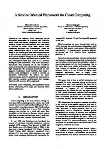
Table 4. Simulation parameters for DBAM. Simulation network was setup such that at any point in time, 33% of the SS are priority SS, next 33% are regular SS and the final 1/3rd are low-priority SS. Each SS generates only eRTPS traffic. Uplink data is generated at the rate of 1Mbps. Downlink ftp traffic was also added. Downlink data is generated at the rate of 1Mbps. Simulation results for throughput are shown in Fig. 4.
410
Wireless Communications and Networks – Recent Advances
Average Throughput (Kbps)
High Priority SS
Regular SS
Low Priority SS
1200 1000 800 600 400 200 0 0
5
10
15
20
25
Number of SS
Fig. 4. Simulation results for throughput for the three types of SS. When the number of MS is 9 each MS has sufficient bandwidth to transmit its data. But, when the number of SS is more than 9, there isn’t sufficient bandwidth to support all SS. DBAM provides bandwidth to high-priroity SS first then regular SS and the leftover bandwidth is shared by low-priority SS. When the number of SS crosses 13, bandwidth for regular SS keeps reducing. Theoretical Results are shown in Figure 5.
Theoretical High Priority SS
Theoretical Regular SS
Average Throughput (Kbps)
Theoretical Low Priority SS 1200 1000 800 600 400 200 0 0
5
10
15 Number of SS
Fig. 5. Theoretical results for DBAM.
20
25
30
411
User Oriented Quality of Service Framework for WiMAX
Comparing figure 4 and figure 5 we see that the simulation results closely follow the theoretical results. By introducing DBAM we can provide graded quality of service to the users. This is a winwin situation for both users and operators. The users win because their data gets prioritized and hence they get a better quality of service. The service providers stand to gain because they get higher revenue for the same amount of data being transmitted. Its just that the order of bandwidth allocation is modified. 2.2 Enhanced Differentiated Bandwidth Allocation Mechanism (eDBAM) In case of DBAM, the order of bandwidth allocation follows the below sequence: High-priority RTPS > Regular priority RTPS > Low-priority RTPS > High-priority nRTPS > Regular priority nRTPS > Low-priority nRTPS > High-priority BE > Regular priority BE > Low-priority BE Basically DBAM ensured that the order of service class is maintained and within the service class we can have graded users. However there is scope for further optimization. We can have seven different ways in which the bandwidth can be allotted. Table 5 and Table 6 list the seven different ways in which bandwidth can be allotted. Each column in the table represents a unique way of bandwidth allotment. The order of allotment is from top to bottom (Kumar et. al, 2011b). DBAM
eDBAM Method 1
eDBAM Method 2
eDBAM Method 3
High-priority RTPS Regular priority RTPS Low-priority RTPS High-priority nRTPS Regular priority nRTPS Low-priority nRTPS High-priority BE Regular priority BE Low-priority BE
High-Priority RTPS High-priority nRTPS High-priority BE Regular priority RTPS Low-priority RTPS Regular priority nRTPS Low-priority nRTPS Regular priority BE Low-priority BE
High-priority RTPS Regular priority RTPS Low-priority RTPS High-priority nRTPS High-priority BE Regular priority nRTPS Low-priority nRTPS Regular priority BE Low-priority BE
High-priority RTPS High-priority nRTPS Regular priority RTPS Low-priority RTPS Regular priority nRTPS Low-priority nRTPS High-priority BE Regular priority BE Low-priority BE
Table 5. Method 1 to Method 3 of eDBAM.
412
Wireless Communications and Networks – Recent Advances
eDBAM Method 4
eDBAM Method 5
eDBAM Method 6
eDBAM Method 7
High-priority RTPS High-priority nRTPS Regular priority RTPS Low-priority RTPS High-priority BE Regular priority nRTPS Low-priority nRTPS Regular priority BE Low-priority BE
High-priority RTPS Regular priority RTPS High-priority nRTPS Regular priority nRTPS Low-priority RTPS Low-priority nRTPS High-priority BE Regular priority BE Low-priority BE
High-priority RTPS Regular priority RTPS High-priority nRTPS Regular priority nRTPS High-priority BE Regular priority BE Low-priority RTPS Low-priority nRTPS Low-priority BE
High-priority RTPS Regular priority RTPS Low-priority RTPS High-priority nRTPS Regular priority nRTPS High-priority BE Regular priority BE Low-priority nRTPS Low-priority BE
Table 6. Method 4 to Method 7 of eDBAM. In eDBAM (for example Method 2), low priority service class of high priority user (ex: Low-Priority BE) can be allocated bandwidth ahead of high-priority service class of regular/low-priority user (Regular/Low priority nRTPS). This out of turn allocation of bandwidth improves the throughput for even low priority service class (BE) for highpriority users. 2.2.1 Implementation Implementation of eDBAM is similar to DBAM. The AAA server shall maintain a mapping of MAC address to the priority value associated with the MAC address. When a MS sends RNG-REQ to BS, BS shall obtain the priority value associated with the MS and allocated bandwidth based on one of the seven methods proposed for eDBAM. BS does not switch between the seven different methods of eDBAM. Each BS shall implement one of the seven methods and stick to that method throughout its operation. 2.2.2 Analytical modeling Throughput modeling follows similar patterns as that of DBAM. Only the order of bandwidth allocation shall change. Delay modeling is explained in this section. The notations used for delay modeling are given in Table 7.
User Oriented Quality of Service Framework for WiMAX
Symbol λ μ ρ L W
413
Description Mean arrival rate Mean service rate Service utilization Mean number of packets of a service flow for a particular SS in the system. Mean end-to-end delay for secure packets of a particular service flow for a particular SS.
Table 7. Delay modeling parameters. For BE packets, Packet arrivals are assumed to have a Poisson arrival.
Pn(t)
(t)n t e n!
(7)
We know that, Service Utilization = Mean arrival rate / Mean service rate. i.e.
(8)
For BE traffic (exponential distribution), mean number of packets for a service flow for a particular-SS is given in (9)
L
1
(9)
Queuing delay for a service flow for a particular SS is given in (10)
L 1 W
(10)
For RTPS and nRTPS we assume constant arrival pattern. So mean number of packets for a service flow for a particular SS is given in (11)
L
(2 ) 2(1 )
(11)
Hence the queuing delay for packets that have constant arrival pattern is: (2 ) 2(1 ) W L
(12)
2.2.3 Simulation of eDBAM Simulation was carried out using NS 2.29. LWX was used to simulate wimax on top of ns2. Simulations were carried out for method-2 for eDBAM. Simulation parameters used, are given in Table-8
414
Wireless Communications and Networks – Recent Advances
Parameter Data rate OFDMA Frame Duration OFDMA symbol time RTPS data arrival rate nRTPS data arrival rate BE data arrival rate
Value 10 Mbps 5 ms 100.94 μs 333 Kbps 333 Kbps 333 Kbps
Table 8. Simulation parameters for eDBAM. Simulation setup was done such that at any given time the network consists of 1/3rd Highpriority SS, 1/3rd Regular-SS and 1/3rd low-priority SS. Each SS is assumed to have RTPS, nRTPS and BE traffic. Downlink ftp traffic at 1 Mbps was introduced. 2.2.3.1 Throughput results Simulation was done to compare the throughput for High-Priority, Regular and LowPriority BE traffic. Fig. 6 shows the simulation results. A comparison with theoretical results is also provided. High Priority BE Regular BE Low Priority BE Theoretical High Priority BE Theoretical Regular BE Theoretical Low Priority BE
400
Throughput (in Kbps)
350 300 250 200 150 100 50 0 -50
0
5
10 15 Number of SS
20
25
Fig. 6. Throughput for BE traffic for the three different types of user. From fig. 6 we see that as the number of SS in the network increases, the throughput form Low-priority BE drops. Subsequently the throughput reduces for regular BE and finally the throughput for High-priority BE. Since method-2 prioritized high-priority BE ahead of Regular nRTPS and Low-priority nRTPS, simulations were carried out for the service flow. Results of simulation are shown in Fig.7.
415
User Oriented Quality of Service Framework for WiMAX High Priority BE Regular nRTPS Low Priority nRTPS Theoretical High Priority BE Theoretical Regular nRTPS Theoretical Low Priority nRTPS 400 350
Throughput (in Kbps)
300 250 200 150 100 50 0 0
5
10
15
20
25
-50 Num ber of SS
Fig. 7. Throughput for High Priority BE v/s Regular nRTPS v/s Low priority nRTPS. 2.2.3.2 Delay results Simulations were carried out to find the delay incurred by the service flows. Fig. 8 shows the delay for High-Priority BE, Regular BE and Low-Priority BE. High Priority BE Regular BE Low Priority BE
3500 3000
Delay (in msec)
2500 2000 1500 1000 500 0 0
5
10
15
20
-500 Num ber of SS
Fig. 8. Delay for High-Priority BE v/s Regular BE v/s Low-Priority BE.
25
416
Wireless Communications and Networks – Recent Advances
Packet delay was measured for High-Priority BE, Regular nRTPS and Low-Priority nRTPS. Results of simulation are shown in Fig. 9.
High Priority BE Regular nRTPS Low Priority nRTPS
3500 3000
Delay (in msec)
2500 2000 1500 1000 500 0 0
5
10
15
20
25
-500 Number of SS
Fig. 9. Delay Results for High Priority BE v/s Regular nRTPS v/s Low Priority nRTPS. From Fig. 8 and Fig. 9 we see that using eBBAM, packets from high-priority SS are subjected to lesser delay compared to regular and low-priority SS. 2.2.3.3 DBAM v/s eDBAM Simulations were done to compare the throughput and delay for DBAM and eDBAM. Fig. 10 shows the throughput comparision for DBAM and eDBAM. We consider method-2 for eDBAM. From Fig. 10 we observe that the throughput for DBAM drops down much before eDBAM. This is because in case of eDBAM, high-priority BE is allotted bandwidth ahead of regular nRTPS and low-priority nRTPS. Figure 11 shows the simuation results for delay. Again eDBAM fairs better than DBAM.
417
User Oriented Quality of Service Framework for WiMAX
High Priority BE eDBAM High Priority BE DBAM 350 300
Throughput (in Kbps)
250 200 150 100 50 0 0
5
10
-50
15
20
25
Num ber of SS
Fig. 10. Throughput comparison for eDBAM and DBAM for high priority BE. High Priority BE eDBAM High Priority BE DBAM
3500
Delay (in msec)
3000 2500 2000 1500 1000 500 0 -500
0
5
10
15
20
25
Number of SS
Fig. 11. Delay results for eDBAM and DBAM for High Priority BE. 2.3 Network Aware Differentiated Bandwidth Allocation Mechanism (nDBAM) Though eDBAM improves the throughput, the algorithm is indifferent to the current network conditions. Especially, if eDBAM method-1 is implemented, it could result in delays for regular and low-priority RTPS. Users might face jitter when they are viewing videos. This might not be desirable. nDBAM takes care of current network conditions before
418
Wireless Communications and Networks – Recent Advances
allocating bandwidth to the different service flows. The steps for nDBAM algorithm as given below. Step 1. Users shall be allotted bandwidth as per one of the selected Seven methods of eDBAM. BS keeps monitoring the network condition. BS could poll the SS to know their current queue length and the average queuing delays faced for each service flow. BS and SS can use the ranging mechanism to pass the information between them. Step 2. If the average queuing delay exceeds the QoS limits for the service class then the BS shall fallback from eDBAM to DBAM bandwidth allocation mechanism Step 3. BS checks with the SS if the average queuing delay has reduced. If yes then BS sticks to DBAM. If the average queuing delay is still high them BS falls back to First-come-first-serve (FCFS) method of bandwidth allocation. Step 4. BS keeps monitoring the queuing delay. If the delay reduces and stays within acceptable limits then BS moves back to eDBAM algorithm 2.3.1 Implementation BS does ranging at periodically with the SS. Ranging process is generally done to adjust the power levels and the clock skews. During the ranging process, BS can also request for the current queue state for the different service flows. As a part of ranging response (RNG-RSP) The SS can send the queue state to BS. The information is generally sent as a TLV (TypeLength-Value) header. A new header will be required to send the queue state information. Table 9 lists an example for the TLV. Type Unused TLV type (ex: 105)
Length 1
Value Average Queue delay for Service flow
Scope RNG-RSP
Table 9. TLV header used to send Queue state. BS receives the RNG-RSP from all the SS for each of their service class. BS then checks if the queuing delay is within the QoS limits for the service class. If not then it means that the eDBAM algorithm is introducing delay for regular and low-priority users. So, BS shifts from eDBAM to DBAM.
3. User based packet classification algorithm We know that WiMAX supports 5 different types of service classes i.e. UGS, RTPS, eRTPS, nRTPS, BE. When a user generates data (ex: video packets) they are classified and placed into one of the 5 queues at SS (ex: Video packets are classified as RTPS packets and placed in the RTPS queue). As the user keeps generating data packets, these are classified and placed in one of the queues. This method of classification is application specific. i.e. if the user keeps generating video packets they are always classified as RTPS packets and placed in RTPS queue and if the user generates web browsing/email packets they are generally classified as BE packets and places in BE queue. Packet classification is not user specific. i.e. there may be some users
419
User Oriented Quality of Service Framework for WiMAX
who are ready to pay more if their browsing packets are treated as high priority packets i.e. the browsing packets generated by such users are treated as RTPS packets instead of BE packets and placed in RTPS queue. There may be some users who may wish to pay less and still enjoy broadband facility. For such users we may want to downgrade even their high priority packets like RTPS packets and treat them as low priority BE packets. A third set of users may fall in-between the highpriority and low-priority users. There shall be 8 different ways of classifying the packets as given in Table 10 (Lagare & Das 2009). Priority
Bit Value
0
000
1
001
2
010
3
011
4
100
5
101
6
110
7
111
Description 802.16e’s existing packet classification mechanism is retained. i.e. real time packets will be placed in RTPS queue. Non real time packets are placed in nRTPS queue and delay tolerant packets are placed in BE queue. RTPS, nRTPS and BE packets are classified as real-time packets and placed in RTPS queue. nRTPS packets are promoted as RTPS packets and all BE packets are promoted as nRTPS packets Only the BE packets are promoted as RTPS packets. Other Packets are placed in their respective priority queues. Only the BE packets are promoted as nRTPS packets. Other Packets are placed in their respective priority queues. RTPS, nRTPS and BE packets are classified as delay tolerant packets and moved to BE queue. RTPS packets will be blocked. This priority level can be set to a certain set of users so that these users can be blocked from transmitting RTPS packets like MPEG videos. RTPS and nRTPS packets will be blocked. This priority can be set to very low priority users.
Table 10. Eight different ways of packet classification. 3.1 Implementation When the MS enters the network, it sends the RNG-REQ to BS. On receiving the range request, BS shall check the priority value associated with the SS. This priority value is passed to the SS in the RNG-RSP. On receiving the priority value the SS shall classify the packets as per table 10. 3.2 Simulation Simulations were carried out to observe the improvement in throughput by implementing user based packet classification. Priority 3 scenario of table 11 was simulated. The simulation network consists of one priority MS whose packets are prioritized as per Priority
420
Wireless Communications and Networks – Recent Advances
3. Other MS are regular users whose packets are prioritized as per priority 1. Table 11 lists the simulation parameters used. Parameter Uplink Bandwidth Uplink Frame Duration Number of Uplink frames per second Maximum Uplink bandwidth per SS per Frame Minimum Reserved Traffic Rate for RTPS Arrival Pattern for RTPS Traffic Arrival Pattern for BE Traffic Average arrival Rate for RTPS traffic Average arrival Rate for BE traffic
Value 2Mbps 1msec (2000 bits) 1000/Sec 400 bits/frame 240Kbps Variable bit rate packets at regular interval of time Poisson Arrival 160Kbps 72Kbps
Table 11. Simulation Parameters. Figure 12 shows the simulation results for BE traffic when the priority MS and regular MS generate both RTPS and BE packets. For priority MS, the BE packets are classified as RTPS packets.
Fig. 12. BE data (in Kbps) transmitted by priority-SS compared to regular-SS. From Fig. 12 we see that, when the number of MS in the network are less than 8, both Priority MS and non-priority MS are able to transmit all their data. When the number of MS in the network goes beyond 8, there isn’t enough bandwidth to support the BE traffic for non-priority users. So the average throughput for non-priority user drops. Since priority MS
User Oriented Quality of Service Framework for WiMAX
421
request bandwidth for their BE traffic as RTPS traffic, priority MS continue to receive bandwidth. Beyond 12 SS there isn’t enough bandwidth to support elevation of BE traffic as RTPS traffic. So throughput for even priority-MS drops down. Fig. 13 shows the simulation results when the network consists of only BE traffic.
Fig. 13. BE data transmitted by priority-MS and regular-MS when only BE packets are present in the network. In Fig. 13 we see that priority MS enjoy constant throughput of 70Kbps where as the throughput for non-priority MS keeps decreasing as the number of MS increases. This happens because BE traffic for priority MS is treated as RTPS traffic. So bandwidth is allotted to priority MS. The leftover bandwidth is shared by non-priority MS. So, by implementing priority based packet classification we can provide graded QoS to the users.
4. User based Call Admission Control (CAC) algorithm Call admission control (CAC) plays a very important role in the IEEE 802.16 based wireless network. WiMAX networks aim to ensure that the QoS requirements for each service class are met. In order to provide QoS, the network should have a robust CAC algorithm. When an SS/MS wants to establish a connection for a particular service class, it sends a DSA (Dynamic Service Addition) request to BS. This DSA request also contains the QoS parameters for the service class. Upon receiving the DSA request the BS decides to accept or reject the connection. If BS accepts the connection then it has to support the QoS needs of that connection. When a BS decides to accept a connection, various factors need to be considered. For example the minimum and maximum data rates on the connection, the delay and jitter parameters for the connection etc. There can be other criteria like fairness, revenue per connection that can also play a role while admitting a connection.
422
Wireless Communications and Networks – Recent Advances
Many CAC algorithms have been proposed both for wired and wireless medium. Because of the unique characteristics of wireless medium, many of the CAC algorithms of wired world cannot be applied to the wireless networks. Researches have proposed some CAC algorithms for WiMAX. In (Chen et. al, 2005) a simple bandwidth based CAC algorithm is proposed. A new connection is accepted if the bandwidth requirements for the connection can be satisfied by the BS. This algorithm does not take into consideration the deadline consideration of the connections. Once the bandwidth is allocated to the connection, the available bandwidth is calculated using the below equation: BW avail BW
Ns
C is [ rate ]
13
s{UGS , RTPS , nRTPS } i 1
Where Cis [rate] represents the data rate for the ith connection which belongs to s service class. In (Chandra & Sahoo, 2007) a QoS aware CAC is proposed. BS contains CAC queues for each service class. So there shall be 5 CAC queues (one each for UGS, RTPS, eRTPS, nRTPS and BE). When an SS makes a CAC request for a particular connection, the BS shall queue the request in one of queues based on the QoS requirements for the Class. BS then goes through each of the queues and accepts the connections. (Chandra & Sahoo, 2007) also provides criteria for call admission for each of the service class. In (Shu'aibu et. al, 2010) (Shu'aibu et. al, 2011) a partition based CAC algorithm is proposed. The total bandwidth is divided into many partitions like constant bit rate partition (CBR), variable bit rate partition (VBR) and Handover partition (HO) etc. CAC is applied to each of these partitions. CAC algorithms proposed above, are all service class based algorithms. In this section we shall look at user based CAC algorithm. The algorithm is based on (Chandra & Sahoo, 2007). 4.1 User based CAC algorithm Fig. 14 shows the control flow at the SS when a new connection request is sent.
Start
Crease DSA request Add the service flow specific QoS parameters to the DSA request Send DSA request to BS
End Fig. 14. User based CAC at SS.
423
User Oriented Quality of Service Framework for WiMAX
Fig. 15 shows the classification of DSA request into different queues based on the priority of user.
Start
Wait for DSA Request from SS
Decide Service Class for the DSA request based on QoS Parameters
Priority User?
Yes
nRTPS
RTPS
UGS
Priority User?
No
Add to priority UGS queue
Yes Add to priority RTPS queue
Add to nonpriority UGS queue
Priority User?
Priority User?
No
Yes
No
Add to priority nRTPS queue Add to nonpriority RTPS queue
BE
No
Yes Add to priority BE queue
Add to nonpriority nRTPS queue
Add to nonpriority nRTPS queue
Fig. 15. Classification of DSA request at BS based on priority of User. Because of lack of space, the control flow of eRTPS service class cannot be shown. However the logic for classifying the DSA request for eRTPS would be similar to UGS. Once DSA requests are classified into the respective queues, BS goes through the DSA requests in each queue to admit the connection. High Level view of Admission control algorithm is given in Fig 16.
424
Wireless Communications and Networks – Recent Advances
AdmissionControlAtBS( ) Begin for each service class (i.e UGS, RTPS, eRTPS, nRTPS and BE) if bandwidth available for each connection request in priority queue of service class if BS can support QoS needs of connection request Admit Connection. if bandwidth available for each connection request in non-priority queue of service class if BS can support QoS needs of connection request Admit Connection. End Fig. 16. User Based Admission control. So, first, connections of priority UGS shall be accepted, followed by Non priority UGS. Priority RTPS and Non Priority RTPS follow next. Once RTPS connections are taken care, priority and Non priority eRTPS connection as admitted in that order. Subsequently priority and Non priority nRTPS connections are admitted. And finally priority and non priority BE connections are admitted. 4.2 Simulation results Silulations were carried out to evaluate the performance of user based admission control algorithm. Simulation Parameters are given in Table-12. Parameter
Value
Uplink Capacity
16 Mbps
Arrival of Connection Requests
Poisson arrival pattern
Lifetime of Connections
2 - 6 seconds
Data rate of UGS connections
256 kbps
Data rate of RTPS connections
256 kbps
Data rate of eRTPS connections
256 kbps
Data rate of nRTPS connections
256 kbps
Data rate of BE connections
256 kbps
Simulation Lifetime
200 seconds
Table 12. Simulation parameters. Simulations were carried out to find the acceptance ratio for the connection requests for priority users and non-priority users. Acceptance ratio is defined as the ratio between the number of connections accepted to the total number of connections requested. Fig. 17 shows the simulation results for acceptance ratio when the network contains only RTPS connections.
425
User Oriented Quality of Service Framework for WiMAX
Connection Acceptance Ratio
1.2 1 0.8
Priority User Non priority User
0.6 0.4 0.2 0 0
10
20
30
40
Connection Arrival Rate (Conn/Sec)
Fig. 17. Connection acceptance ratio for RTPS connections. From Fig. 17 we can see that till the connection arrival rate is 10 connections/sec, there is enough capacity to accept both priority and non-priority connections. But beyond that the network cannot support the connection. So it starts to reject the connection. Since connection requests from priority users are processed first, the acceptance ratio for priority users would be higher compared to non-priority users. Fig. 18 shows the simulation results for RTPS connections for different uplink capacities.
Connection Acceptance Ratio
1.2 1
Priority User 16Mb Link capacity
0.8
Non priority User 16Mb Link Capacity
0.6
Priority User 18Mb Link capacity
0.4
Non priority User 18Mb Link Capacity
0.2
Priority User 20Mb Link capacity
0 0
10
20
30
40
Non priority User 20Mb Link Capacity
Connection Arrival Rate (Conn/Sec)
Fig. 18. Connection acceptance ratio for RTPS connection at different uplink capacities.
426
Wireless Communications and Networks – Recent Advances
Simulations were also carried out to check the performance of user based admission control algorithm when BS receives connection requests for all the types of service classes i.e UGS, RTPS, nRTPS, eRTPS and BE. Fig 19. illustrates the simulation results for this scenario.
Connection Acceptance Ratio
1.2 priority UGS
1
Non priority UGS
0.8
priority RTPS Non priority RTPS
0.6
priority eRTPS
0.4
Non priority eRTPS priority nRTPS
0.2
Non priority nRTPS priority BE
0 0
10
20
30
40
Non priority BE
Connection Arrival Rate (Conn/Sec)
Fig. 19. Connection acceptance ratio for connections from different service classes. From the simulation results it is clear that implementing user based admission control improves the connection acceptance ratio for priority users, there by improving the broadband experience for this section of users. 4.3 Drawback of user admission control If, at any point in time, the network receives many connection requests from priority users then there is a chance that the non-priority users might see higher rejections of their connections. This can be tackled at the operator level. Based on the capacity of the network, a network service provider can limit the number of priority users that he can support. So when signing a new user, the operator can decide whether he wishes to provide the user the privilege of being a priority user.
5. Conclusion In this chapter a comprehensive user based framework is proposed across various modules in WiMAX. Though operator can provide graded services by having different data rates at different price points, it does not give the flexibility that user based framework provides. Using the user based framework, graded services can be managed at the MAC layer and users can be up-graded/down-graded dynamically.
6. References Chandra S. & Sahoo A. (2007), An efficient call admission control for IEEE802.16 networks, in Proceedings of the 15th IEEE Workshop on Local and Metropolitan Area Networks, pp. 188–193, ISBN 1-4244-1100-9, Princeton, NJ, USA, June 2007
User Oriented Quality of Service Framework for WiMAX
427
Chen J.; Jiao W. & Wang H. (2005), A Service Flow Management Strategy for IEEE 802.16 Broadband Wireless Access Systems in TDD Mode, IEEE International conference on Communication, pp. 3422 - 3426, ISBN 0-7803-8938-7, May 16-20 2005 Chen Y. H. (2008), Light WiMAX Module, Available from http://code.google.com/p/lwx/ Chiang C.H.;Liao W.; & T. Liu (2007), Adaptive Downlink/Uplink Bandwidth Allocation in IEEE 802.16 (WiMAX) Wireless Networks: A Cross-Layer Approach, IEEE Global Telecommunications Conference, pp. 4775-4779, ISBN 978-1-4244-1043-9, Washington DC, US, Nov. 26-30 2007 IEEE (2004). IEEE 802.16, Air Interface for Fixed Broadband Wireless Access Systems, ISBN 07381-4070-8 IEEE (2005). IEEE 802.16e, Amendment to IEEE Standard for Local and Metropolitan Area Networks - Part 16: Air Interface for Fixed Broadband Wireless Access Systems - Physical and Medium Access Control Layers for Combined Fixed and Mobile Operation in Licensed Bands Kumar N.; Murthy K. N. B. & Lagare A. M. (2011), DBAM: Novel User Based Bandwidth Allocation Mechanism in WiMAX, 2nd International Conference on Recent Trends in Information, Telecommunication and Computing, pp. 229-236, ISBN 978-3-642-19541-9, March 2011 Kumar N.; Murthy K. N. B. & Lagare A. M. (2011), User oriented Network aware bandwidth allocation in wimax, International Journal on Recent Trends in Engineering and Technology, vol. 5, no. 1, pp 8-14, ISSN 2158-5555, March 2011 Lagare A.M.; Das D. (2009). Novel user-based packet classification in 802.16e to provide better performance, IEEE 3rd International Symposium on Advanced Networks and Telecommunication Systems (ANTS), pp. 1 - 3, ISSN: 2153-1676, Dec 2009 Lee N.; Choi Y.; Lee S. & Kim N. (2010), A new CDMA-based bandwidth request method for IEEE 802.16 OFDMA/TDD systems, IEEE Communications Letters, Vol 14, Iss 2, pp 124-126, ISSN 1089-7798, Feb 2010 Lin Y.N.; Wu C.W.; Lin Y.D. & Lai Y.C. (2008), A Latency and Modulation Aware Bandwidth Allocation Algorithm for WiMAX Base Stations, IEEE Wireless Communications and Networking Conference, pp. 1408-1413, ISBN 978-1-4244-1997-5, Las Vegas, Nevada, US, March 31 - April 3 2008 Liu C.Y. & Chen Y.C. (2008), An Adaptive Bandwidth Request Scheme for QoS Support in WiMAX Polling Services, Proceedings of The 28th International Conference on Distributed Computing Systems Workshops, pp. 60-65, ISBN 978-0-7695-3173-1, Beijing , China, June. 17-20 2008 ns2, Available from http://www.isi.edu/nsnam/ns/ Park E.C. (2009), Efficient Uplink Bandwidth Request with Delay Regulation for Real-Time Service in Mobile WiMAX Networks, IEEE Transaction on Mobile Computing, Vol. 8, Iss. 9, pp. 1235-1249, ISSN 1536-1233, Sept. 2009 Peng Z.; Guangxi Z.; Haibin S. & Hongzhi L. (2007), A Novel Bandwidth Scheduling Strategy for IEEE 802.16 Broadband Wireless Networks, Proceedings of International Conference on Wireless Communications, Networking and Mobile Computing, pp. 20002003, ISBN 978-1-4244-1311-9, Shanghai, China, Sept. 21-25, 2007 Rong B.; Qian Y. & Chen H.H. (2007), Adaptive power allocation and call admission control in multiservice WiMAX access networks, IEEE Wireless Communications, Vol. 14, Iss. 1, pp. 14-19, ISSN 1536-1284, Feb 2007
428
Wireless Communications and Networks – Recent Advances
Shu'aibu D. S.; Syed-Yusof S. K. & Fisal N. (2010), Partition-base bandwidth managements for mobile WiMAX IEEE802.16e, International Review on Computers and Software, vol. 5, no. 4, pp. 445–452 Shu'aibu D. S. (2011), Fuzzy Logic Partition-Based Call Admission Control for Mobile WiMAX, ISRN Communications and Networking, Article ID 171760, ISSN 2090-4355, April 11, 2011 Tao S. Z. & Gani A. (2009), Intelligent Uplink Bandwidth Allocation Based on PMP Mode for WiMAX, Proceedings of the 2009 International Conference on Computer Technology and Development, pp. 86-90, ISBN 978-0-7695-3892-1, Kuala Lumpur, Malaysia, Nov. 1315 2009 Vaughan-Nichols, S. J. (2004), Achieving Wireless Broadband with WiMAX, IEEE Computer, Vol. 37 Iss. 6 , pp. 10-13, ISSN: 0018-9162 Wee K. K. & Lee S. W. (2009), Priority based bandwidth allocation scheme for WIMAX systems, Proceedings of 2nd IEEE International Conference on Broadband Network & Multimedia Technology, pp. 15-18, ISBN 978-1-4244-4590-5, Cyberjaya, Malaysia, Oct. 18-20 2009