EPJ Web of Conferences 195, 09006 (2018) TERA-2018
https://doi.org/10.1051/epjconf/201819509006
Using a Gyrotron as a Source of Modulated Radiation for Data Transmission Systems in the Terahertz Range A. I. Tsvetkov, A. P. Fokin, A. S. Sedov, M. Yu. Glyavin Institute of Applied Physics of the Russian Academy of Sciences, Nizhny Novgorod, Russia,
[email protected]
The report describes results of preliminary experiments on using low THz range gyrotron (263 GHz) with medium output power (up to 1 kW in CW mode) as a modulated radiation source for data transmission. It was demonstrated up to 1.5 Mbit/s data rate. Estimates show that at relatively low costs it is possible to build a gyrotron-based system with a speed of about 1 Gbit/s. The scientific community is actively discussing the possibility of promotion of data transmission systems in the subterahertz and terahertz frequency range [1 ̶ 5]. Data transmission in these bands is attractive for a number of reasons including noise immunity and the complexity of signal interception. It should be taken into account that communication links at such high frequencies suffer from attenuation due to polar molecules (mainly H2O and O2) in the atmosphere in addition to the large free-space loss. A suitable transmission window of atmospheric transparency can be found at 200 – 300 GHz [6]. Another complication in the implementation of low THz communication systems is the lack of sufficiently powerful radiation sources with flexible capabilities to control the output radiation parameters in these ranges. The experiments described below demonstrate the possibility of using a subterahertz gyrotron for the data transmission. There are various methods of control of the output power and frequency of electron devices. One of the most used approaches for the gyrotrons is the variation of the potential of one of the electrodes of the magnetron-injection gun (MIG). The most economical way to quickly control the output parameters is to change the voltage at the isolated anode. This fact is caused by small capacity of anode relative to other electrodes and low anode current, so there is no need in complex and expensive power supplies. The change of anode voltage does not alter the electron energy, but only its pitch-factor (ratio of it orbital to longitudinal velocity). Such change of pitch-factor leads to change of the electron beam complex susceptibility and, hence the change of the interaction condition and, finally, frequency and amplitude of the oscillations. To control the gyrotrons output parameters the fast anode voltage control unit was developed that allows gyrotron anode voltage to be modulated in range of 1 kV with slopes better than 1 kV/µs. The active element of the control unit is the tetrode; the voltage drop is proportional to the external control signal. It was demonstrated up to 200 kHz modulation frequency bandwidth in recent experiments. In the latest experiments performed in the Institute of Applied Physics of the Russian Academy of Sciences (IAP RAS), the gyrotron with an output frequency f 0.26 THz was equipped with the PLL sys-
tem for its frequency stabilization, which was implemented on the basis of the fast variation of the anode potential. Such an approach made it possible to demonstrate the width f of a gyrotron radiation spectrum of about 1 Hz, which corresponds to the relative value of f / f 310-12[7]. The created control system was then used for the experiments described below demonstrating the principle possibility of using a lower terahertz range gyrotron for the information transmission. This paper reports on experiments in which it was first realized the transmission of an AM modulated radio signal for several meters using a 263 GHz gyrotron [8] radiation with up to 1 kW power as a carrier.
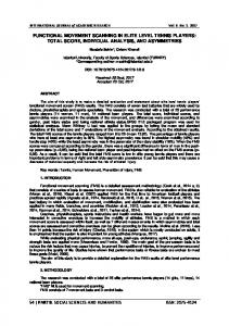
Fig. 1. Diagram of the experimental setup
An ultrafast terahertz (50 GHz – 0.7 THz) detector developed by TeraSense company [9] was used as a radiation receiver and for detecting the AM signal. The detector was installed almost on the path of the gyrotron radiation beam propagation at a distance of several meters from the output vacuum window. The voltage at the anode of the gyrotron was recorded with a NorthStar PVM-5 [10] fast high-voltage probe. Demonstration experiments were carried out at the gyrotron output power level of about 50 W, which in no way limits their generality. Similarly, the parameters of this gyrotron can be controlled at any output power level up to 1 kW. An audio recorder that provides a level of a modulation signal in the 0 – 10 V range was used in the first experiment. At the same time, the terahertz detector signal was applied to both an oscilloscope and an audio frequency amplifier, followed by output to a loudspeaker. Successful analog transmission of several audio recordings was demonstrated. Fig. 2 shows examples of oscillograms of the corresponding sound signals.
© The Authors, published by EDP Sciences. This is an open access article distributed under the terms of the Creative Commons Attribution License 4.0 (http://creativecommons.org/licenses/by/4.0/).
EPJ Web of Conferences 195, 09006 (2018) TERA-2018
https://doi.org/10.1051/epjconf/201819509006
power circuit, applying more complex methods for gyrotron output parameters control, using advanced digital signal modulation schemes, increasing the power in the data transmission channel. Simple estimates using the Shannon-Hartley theorem show that it is possible to achieve at least 1 Gbps of channel capacity (under practically the same experimental conditions) by increasing bandwidth of the channel with an improved anode power supply. It is clear that one of the next steps should be a study of the transmission system with respect to various modulation schemes and different symbol rates. The work was partially supported by the Russian Federation President Grant No. MK-3452.2017.8. References 1. J. Federici and L. Moeller, “Review of terahertz and subterahertz wireless communications,” Journal of Applied Physics, 107, 111101 (2010). 2. T. Kleine-Ostmann and T. Nagatsuma, “A review on terahertz communications research,” J. Infrared, Millimeter, and Terahertz Waves, 32,143-171 (2011). 3. H.-J. Song and T. Nagatsuma, “Present and future of terahertz communications,” IEEE Trans. Terahertz Science and Technology, 1, 256-263 (2011). 4. T. Nagatsuma et al., “Terahertz wireless communications based on photonics technologies,” Opt. Express, 21, 23736-23747 (2013). 5. T. Kürner and S. Priebe, “Towards THz communications-status in research, standardization and regulation,” J. Infrared, Millimeter, and Terahertz Waves, 35, 53-62 6. V. Petrov, A. Pyattaev, D. Moltchanov and Y. Koucheryavy, “Terahertz band communications: Applications, research challenges, and standardization activities,” in 8th International Congress on Ultra Modern Telecommunications and Control Systems and Workshops (ICUMT), Lisbon, pp. 183-190, Oct. 2016. 7. A. Fokin et al. High-power sub-terahertz source with a record frequency stability at up to 1 Hz // Scientific Reports, 8, 4317 (2018) 8. M. Glyavin et al. Experimental tests of 263 GHz gyrotron for spectroscopy applications and diagnostic of various media // Review of Scientific Instruments, 86, No. 5, 054705 (2015) 9. TeraSense: «Ultrafast Terahertz Detectors». URL: http://terasense.com/products/detectors/. 10. North Star High Voltage: «High Voltage Probes». URL: http://www.highvoltageprobes.com/high-voltageprobes
Fig. 2. Top – oscillogramms of the detector signal (1), anode voltage (2), modulation signal of the audio recorder (3); bottom – pseudo-random bit sequence: control (modulating) signal of 33521B generator (1), terahertz detector signal (2).
One can see in Fig. 2 (top) that for some values of the amplitude of the carrier signal the oscilloscope trace obtained from the terahertz detector is distorted with respect to the modulating signal. This is due to the nonlinearity of the slope of the regulating element used in the anode voltage control unit (this effect is especially noticeable near the 0 V control signal) and can in principle be compensated by the choice of a suitable control signal bias. In the second experiment, the arbitrary waveform generator Agilent 33521B has been used as a source of the control (modulating) signal. It was demonstrated the transmission of a digital signal - a pseudorandom bit sequence (an example of an oscillogram is shown in Fig. 2). In this case, just as in the previous experiment, simple amplitude modulation of the signal was used. Up to a data rate of about 1.5 Mbit/s, the logical levels of the received (detected) signal were resolvable. The authors believe that the achieved data transfer rate is far from the principal limit and can be increased by decreasing the time constant of the anode
2