University of York, York, YO10 5DD, UK. {martin.hall-may, tim.kelly}@cs.york.ac.uk. Abstract. A safety policy defines the set of rules that governs the safe interac-.
Using Agent-based Modelling Approaches to Support the Development of Safety Policy for Systems of Systems Martin Hall-May and Tim Kelly Department of Computer Science University of York, York, YO10 5DD, UK {martin.hall-may, tim.kelly}@cs.york.ac.uk
Abstract. A safety policy defines the set of rules that governs the safe interaction of agents operating together as part of a system of systems (SoS). Agent autonomy can give rise to unpredictable, and potentially undesirable, emergent behaviour. Deriving rules of safety policy requires an understanding of the capabilities of an agent as well as how its actions affect the environment and consequently the actions of others. Methods for multi-agent system design can aid in this understanding. Such approaches mention organisational rules. However, there is little discussion about how they are derived. This paper proposes modelling systems according to three viewpoints: an agent viewpoint, a causal viewpoint and a domain viewpoint. The agent viewpoint captures system capabilities and inter-relationships. The causal viewpoint describes the effect an agent’s actions has on its environment as well as inter-agent influences. The domain viewpoint models assumed properties of the operating environment.
1 1.1
Introduction Making Systems of Systems Safe
A system of systems (SoS) is a large-scale network of autonomous, heterogeneous, and often mobile entities that are individually purposeful, and yet are expected to interoperate towards a common purpose. SoS are, perhaps more than single platform systems, characterised by the interaction of feedback loops. Astonishingly complex behaviour can arise from the iteration of relatively simple cycles of behaviour. The term ‘OODA’ — observe, orient, decide, act — coined by Boyd [1], describes the process of relating perceptions of the environment to actions in that same environment, which allows systems to interact and operate together in a shared space. It is just this interaction of many autonomously operating cycles of behaviour that can give rise to hazards, and hence to accidents. The authors explained in [2] that a safety policy can be used to restrict the behaviour of the component systems of a SoS such that hazards are avoided or mitigated through corrective action. As described in this paper, a safety policy decomposition proceeds from top-level safety objectives down to low-level constraints on system behaviour. However, at each step of the decomposition assumptions are inevitably made that relate to mental models of the system of systems whose behaviour the policy is intended to govern. Making these models explicit is a first step towards allowing the information
that they contain to be used in a systematic policy decomposition process. Developing such models is not the principal concern of deriving a safety policy, but is a necessary precursor to a successful decomposition. The informal role of models in policy making is well established [3]. Theoretical as well as empirical models are used by Government and other decision makers to set policies on a number of issues, ranging from health and the economy to the environment. Indeed, the defence industry uses models to guide combat decisions based on their knowledge, assumptions and best guesses of enemy capability, the anticipated operational environment as well as the configuration and inter-operation of their own forces. In order to inform a policy decomposition we must have an understanding of the environment in which the systems are expected to operate, the type of knowledge they employ in decision-making processes, the capabilities they have and the ways in which these are used to interact with one another.
1.2
Learning from Multi-Agent Systems
It has been said that “much confusion still remains about words and phrases for systemsof-systems type problems, let alone the best modeling approaches for dealing with them” [4]. There is surprisingly little consensus on appropriate modelling techniques. Is it perhaps possible to draw inspiration from related domains whose problem areas share the characteristics of SoS? Indeed, the community of research concerning the design of intelligent agents would seem to be a rich area with much to contribute to our area of research. Multi-agent systems (MAS) deal with the problem of many interacting autonomous agents, each of which may have its own goals and objectives. Although multi-agent systems would seem germane to the problem area of SoS, it is important to recognise key differences. Often the focus of a MAS is on software agents (as opposed to embodied agents) and agents are described as ‘mobile’ only in the sense that they can move their code between hosts. These software agents act primarily in the ‘information’ world, whereas our focus is on agents that can also act in the physical world — e.g. an unmanned air vehicle (UAV). It is worth highlighting that agents are still considered embodied even if they are operating in a simulation of the real world. Contrast, for example, a simulation of a UAV agent with a meeting scheduler agent. Pynadath and Tambe [5] sum up the agent community’s very different approach to safety, as the cancellation by an agent of a meeting that a human intended to attend is considered a ‘catastrophic’ event. SoS and MAS share many characteristics, among them autonomous entities, local knowledge and decentralised decision-making. However, it is also necessary to recognise the primary distinction between them, namely that a SoS comprises entities that are capable of physical, not just computational, interaction. This capability is arguably the reason that the term SoS is much used in the military domain and is key in investigating issues of safety, since physical interaction is a prerequisite for death or injury to occur.
1.3
Structure of the Paper
Section 2 will expand on the notion of a safety policy. Sections 3–5 will introduce three viewpoints by which a SoS can be modelled. Section 6 will examine how these models can be used to inform a safety policy decomposition. Section 7 will summarise the paper. Throughout the paper we will illustrate concepts and techniques where possible with reference to an example SoS for the military domain. Figure 1 gives a representation of the example SoS, which depicts a minimal set of systems operating together necessary to mount an attack and to clear a given region of a guerrilla enemy force. The systems communicate via a shared ‘data fusion’ picture, indicated by jagged lines, and include a UAV with sensors capable of target identification, long range artillery capable of launching suppressing fire on a target and infantry (carried by transport helicopters) capable of neutralising an already suppressed target.
Fig. 1. A Concept View of a System of Systems for Anti-guerrilla Operations (AGO)
2
Safety Policy
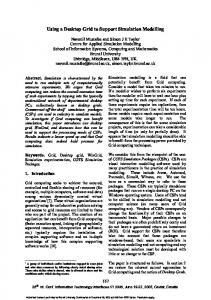
Pynadath and Tambe [5] state that “it is unreasonable (if not impossible) to have humans specify sufficient safety conditions to completely determine correct agent behaviour”. Quite so, the important distinction is that safety policy specifies constraints that are orthogonal to normal functional behaviour. A safety policy aims to circumscribe the potentially hazardous but functionally possible behaviour, in such a fashion that it leaves only that which is considered acceptably safe. It is not the job of safety policy to define functionally correct behaviour — for this is merely rigorous specification — policy is separate from the behaviour to achieve goals. Sørby [6] describes a safety policy as being analogous to security policy in that it influences the stakeholders in a system by enforcing a number of safety requirements, which are in turn influenced by safety standards (see Figure 2). Taken together, the set of safety requirements should ensure the safety of the system.
Safety ensures enforces 1..*
1
Safety Policy
influences 1
1..*
Stakeholders
Safety Requirements 1..* influences
1..*
Safety Standards
Fig. 2. Excerpt of Sørby’s Safety Ontology Relating Safety Policy to Safety Requirements
MAS development often mentions organisational rules [7], however there is generally little explanation of how the rules are derived. This paper represents a step towards a more structured, systematic process to their derivation, which increases traceability of rules from high-level objectives and increases confidence in the completeness of the rule set. Policy is a hierarchical decomposition of high-level policy objectives into constraints over agent actions and interactions. The Goal Structuring Notation (GSN) [8] — typically used to construct safety cases — can be used to represent policy decomposition structures. To support policy decomposition, we propose modelling the SoS from three viewpoints: an agent viewpoint, a domain viewpoint and a causal viewpoint. The agent viewpoint captures the technical aspects of the SoS and its constituent component systems, including their attributes and relationships in terms of planned interactions. A domain viewpoint provides a consistent terminology and model of the SoS environmental assumptions. A causal viewpoint focuses on the way factors such as actions, states and other variables influence each other in the SoS, potentially leading to unplanned interactions. These viewpoints are the focus of this paper.
3
Agent Viewpoint
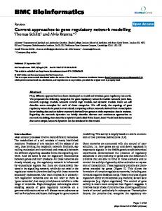
Despite the recent increase in interest in engineering systems of systems [9], there has been little consensus on a successful modelling approach. An object-oriented (OO) approach has been recommended for the specification and analysis of requirements for systems of systems [10, 11]. Caffall and Michael propose treating the SoS as a single entity comprising abstract classes, rather than decomposing the SoS into its constituent systems in a functional fashion. Agent UML [12] extends the standard Unified Modelling Language typically used to model OO systems in various ways to enable agent-oriented design. As previously mentioned, MAS techniques often focus on software agents. Commensurately, Agent UML focuses on capabilities in terms of logical or mathematical operations and services such as ‘computation’, rather than capabilities for physical interaction. The PASSI (Process for Agent Societies Specification and Implementation) methodology makes use of conventional and agent UML notation to express five different models of increasing specificity for the design of agent-based societies [13]. The process can be viewed as comprising analysis and design activities. For the purposes of this paper we concentrate on the analysis phase, including the modelling of system requirements
3. Agent Implementation Model. A classical model of using a class derived from the base-agent type of the chosen the solution architecture in terms of classes and platform; the tasks will be implemented as subclasses of the methods, the most important difference with common agent-class and the actions are methods of these classes. In Object-oriented approach is that we have two this perspective, a role will be the result of a series of different levels of abstraction, the social (multibehaviors realized by the actions of several different tasks of agent) level and the single-agent level. This model is the same agent. composed of the following steps: (a) Agent Structure We will illustrate the methodology with an example coming Definition (A.S.D.): Conventional class diagrams from robotics: we will design a multi-agent system in order to describe the structure of solution agent classes. (b) obtain some specific behaviors from a robot provided with Agent Behavior Description (A.B.D.): Activity video, IR and odometry sensors. diagrams or statecharts describe the behavior of We will illustrate the methodology with an example coming individual agents. from robotics: we will design a multi-agent system in order to 4. Code Model. A model of the solution at the code obtain some specific behaviors from a robot provided with level requiring the following steps to produce: (a) and the agent society. Each of the five models has several phases, each of which utilises video, IR and odometry sensors. Generation of code from the model using one of the a particular (Agent) UML diagram to capture specific information. functionalities of the PASSI add-in. It is possible to The models and phases of PASSI are: generate not only the skeletons but also largely 1. System Requirements Model. A model of the reusable parts of the methods implementation based system requirements in terms of agency and purpose. Initial Requirements
Next Iteration
System Requirements Model
Agent Implementation Model
Domain Description
Multi-Agent
Single-Agent
Structure Definition
Structure Definition
Behavior Description
Behavior Description
Agents Identification
Roles Identification
Tasks Specification
Code Production
Agent Test
Roles Description
Ontology Description
Code Model
Deployment Configuration
Protocols Description
Agent Society Model
Deployment Model
Society Test
Fig. 1. The models and phases of the PASSI methodology
Fig. 3. The Models and Phases of the PASSI Methodology
Figure 3 shows the relationships between the models and phases of PASSI. PASSI encourages identification of agents early on in the development process. This is supported by the claim that the types of MAS targeted by this process comprise agents that can be ‘bidden’ or influenced but not deterministically controlled [14]. Therefore, it is desirable to allocate required behaviours to “loci of responsibility” as soon as possible. Agent Identification Diagram
TheatreCommand Secure Area
User
(from TheatreCommand)
(from 01-Domain D...)
Share Intelligence
Artillery
(from TheatreCommand)
Suppress Enemy
Deliver Artillery Fire
(from Artillery)
(from Artillery)
Infantry UAV
Neutralise Enemy (from Infantry)
Scan Air
(from UAV)
Patrol Area
Detect Enemy
(from UAV)
(from UAV)
Scan Ground
Environment (from 01-Domain D...)
(from UAV)
Helicopter Deploy Special ForcesTransport Special Forces (from Helicopter)
(from Helicopter)
Target File: H:\rose\AGO2.mdl
08:53:47 03 March 2006
(from 01-Domain D...) Use Case Diagram: 02-Agent Identification phase / Agent Identification Page 1
(1, 1)
Fig. 4. An Agent Identification Diagram for the AGO System of Systems
Using the PASSI methodology the example SoS configured for anti-guerilla operations and presented in Figure 1 has been modelled. Figure 4 shows a description of the SoS in terms of use cases. The use cases represent the domain of functionality of the
SoS, and external actors have been identified with which the SoS interacts. These are the user of the SoS, which is most likely to be a set of commands coming from outside of the theatre of interest, the environment and the enemy targets. Delineating what is inside the system boundary is a significant challenge even for a single platform, and respectively more difficult for a SoS [15]. In order to secure the area, the enemy must be detected (distinguished from the environment), suppressed and finally neutralised altogether. Due to the large geographical nature of the area of interest, more than one system is needed to secure it. Due to the nature of SoS, i.e. the systems are geographically dispersed, but can only act and observe locally, there is also a need to share intelligence between them. The agent identification diagram is derived from a higher level domain description diagram, which is not shown here due to space constraints. An agent is described as a package of use cases. The use cases that make up the functionality of the SoS have been assigned as the responsibility of one of five agents: artillery, infantry, UAV, helicopter or theatre command. : User
: User
Controller : TheatreCom...
Nominator : UAV
Suppressor : Artill...
Transporter : Helic...
Confirmer : UAV
Neutraliser : Infantry
Fuser : TheatreCommand
: Env...
: Tar...
Controller : TheatreCommand
Nominator : UAV
Suppressor : Artillery
Transporter : Helicopter
Confirmer : UAV
Neutraliser : Infantry
Fuser : TheatreCommand
: Environment
: Target
1: StartMission 2: OrderPatrolArea 3: PatrolArea 4: Update(targetPos) 5: QueryTargets 6: Target(pos) 7: FireShell 8: Update(targetSuppressed) 9: QueryTargets 10: TargetSuppressed(pos)
11: QueryTargets 12: Target(pos) 13: OrderTakeOff 14: Destroy
15: Update(targetNeutralised) 16: QueryTargets 17: TargetNeutralised(pos) 18: QueryTargets 19: NoTargesRemaining 20: MissionComplete
Fig. 5. A Role Identification Sequence Diagram for the AGO System of Systems
Figure 5 shows the role identification diagram, which describes an envisaged scenario. This diagram adds detail to the «communicate» relationships between agents in Figure 4 by identifying the role that agents play and the sequence in which messages occur. The role identification diagram is abstract, in that it does not show the reality of the interactions. An agent viewpoint is important when developing policy in order to consider the types of communications that will occur as well as which agent relies on the services or knowledge of another. File: H:\rose\AGO2.mdl
08:55:58 03 March 2006
Sequence Diagram: 03-Role Identification phase / Anti-guerrilla Page 1
4
Domain Viewpoint
The PASSI methodology employs a knowledge-centric agent model. Agents act to achieve their objectives on the basis of local goals and knowledge, which increases through communication with other agents and exploration of the real world. It is interesting to note that PASSI eschews the use of Agent UML’s extension to the class diagram in favour of the conventional notation for representing agents. Instead, knowledge is represented in the domain ontology description phase as a conventional class diagram, where each class represents a concept, a predicate or action on that concept. The communication ontology description diagram shows the agent and its ascribed knowledge attributes and the communicative relationships between them. Communication among agents is considered different to that between agents and external ‘actors’. Principally, agent communication proceeds according to certain protocols and uses a specific ontology. Communication with agents not part of the SoS (e.g. the enemy, non-squad troops) might occur indirectly through sensing devices. The representation of knowledge is very important to mental models, and therefore highly relevant to our particular application (since inconsistencies between agents’ mental states are a significant factor in the cause of SoS accidents). Hence, even though PASSI allows us to model knowledge using class diagrams, it is worthwhile treating the construction of the domain viewpoint as a significant exercise in its own right. An ontology represents knowledge of what exists — from the Greek ontos (that which exists) + logos (knowledge of) — and is important in order to disambiguate concepts in communications between agents. When one agent talks to another about an ostensibly common concept, they might have very different mental images of what is being discussed. For instance, consider the potential for confusion when discussing the many definitions of the word ‘target’. However, the confusion may be even more subtle, as was the case with the mix-up between imperial and metric units that allowed the Mars Climate Orbiter to fly too close to the planet’s surface and thus be destroyed [16]. Ontologies are used in domain modelling, conceptual modelling and knowledge engineering. Aside from providing a common understanding and vocabulary, they can be used to give meaning and potentially a taxonomical organisation to domain terms provided by a subject-matter expert (SME). According to Guarino and Welty [17], “ontologies are becoming increasingly popular in practice, but a principled methodology for building them is still lacking.” Indeed, there are many ways in which one might build an ontology from a data dictionary as provided by a SME. What is needed is an organising principle with which to structure the ontology. Much work has gone into creating so-called upper ontologies. These include Cyc [18], SUMO [19] and SENSUS [20], which describe high-level terms, under which domain-specific ontologies can be organised. The upper ontology typically includes concepts such as physical, tangible and abstract entities. A mid-level ontology might include specialised versions of these concepts to do with time and space. Finally, a domain ontology is geared towards the particular application of interest. Valente et al [21] suggest for a military application the use of several ontologies including terms encompassing Communications, Organisations, Physical resources and Service descriptions.
Domain Ontology Description Diagram
WorldDescription
1
1 SelfDescription
EnvironmentDescription
GeodeticCoordinateSystem latitude longitude
0..n TargetDescription
GetTargetInfo
SelfPosition X Y TheatrePicture Targets[] : TargetPositi...
Get()
isTarget value : Boolea ...
TargetPosition X Y
isSuppressed value : Boolea ...
SARSensorData SensorValue[] : i...
UpdateTheatrePicture Update()
isNeutralised value : Boolea ...
Fig. 6. A Domain Ontology Diagram for the AGO System of Systems
Figure 6 shows the domain ontology diagram for the AGO system. This is necessarily simplified and could potentially be extended to include the standard terms provided by any of the above-mentioned upper ontologies. Accompanied by the communications ontology diagram, which ascribes ontologies to agents as concepts to be used in communications, this gives an indication of how the misinterpretation of common realworld artifacts in local mental models can occur. File: H:\rose\AGO.mdl
5
10:22:34 03 March 2006
Class Diagram: Domain / Domain Ontology Description Page 1
Causal Viewpoint
The causal viewpoint recognises that accidents in a SoS arise out of, as Perrow described, dysfunctional interactions [22]. The accident model, STAMP [23], recognises the importance of this type of interaction in safety-critical applications. Similarly, we must take a more systems-theoretic approach to describing the relationships between causal factors in the lead up to an accident, rather than traditional chain-of-event failure models such as Fault Trees. As described, the behaviour of a SoS is typified by multiple interacting feedback loops. This means that it is not possible to take a mechanical approach to working through the causal chain, because many factors influence each other as well as, indirectly, themselves. The inter- and intra-agent behaviour can be described as a feedback-based loop “observe, orient, decide, act” (OODA). Orient means updating one’s mental model based on new observations, where these are interpreted through experience, training, traditions, previous observations etc. The interpreted observations allow the agent to decide among a number of alternatives and to enact the chosen one, causing some effect on the environment. A consideration of the OODA cycle of agent behaviour can help in structuring the task specification diagram for individual agents. In Figure 7 the UAV goes through a cycle of scanning the ground for threats (observation), processing the data (orientation),
UAV T.Sp.:Interacting Agents
UAV
ScanGround
IdentifyTarget
Theatre Command.UpdateTheatrePicture
ObserveTarget Suppressed
ObserveTarget Neutralised
SendTargetUpdate
Fig. 7. A Task Specification Diagram for the UAV Agent
deciding whether the data represents a new threat or a change to the state of an existing known target (decision) and finally passing this information to Theatre Command (action). It is only during the observation and action activities that interaction with other agents can occur. When observing, the agent not only uses its own senses to investigate the environment but can also integrate information provided by other agents. Similarly, it can provide the results of its decision-making process to other agents through its actions. Figure 8 shows several loops for the Theatre Command agent, whose behaviour is more complicated than the UAV and which interacts with (influences) more agents in so doing. The sequence diagram (Figure 5) describing the interaction between roles in the AGO scenario must be consistent with the task specification diagrams. That is, the sequence of events described must be able to be generated from the interaction of all the agents’ OODA cycles. It is clear, however, that the task specification models do not capture all the unplanned interactions that are required when considering how to develop a safety policy. Planned actions are those that it is anticipated the agent will undertake in order to complete its task. We want to model agents with only local abilities and imperfect knowledge, i.e. they cannot assess the current state of the world, nor observe the effects of their actions on all other agents. The causal viewpoint needs to capture problems of failure, uncertainty and the effects of an agent’s actions. For this we can take inspiration from another branch of agent theory, namely Multi-agent Influence Diagrams (MAIDs) [24]. MAIDs are an extension to Bayesian Belief Networks (BBNs) and decision networks. Using them it is possible to represent how agents’ decisions are influenced by various factors. These factors include probabilistic variables (represented by circular ‘chance’ nodes) that are in effect ‘decided’ by the environment, as well as the results of other agents’ decisions (rectangular nodes). Decision networks also require specifying the utility of the decisions to the agents, i.e. their preference for the result of a particular decision (represented by diamond-shaped nodes). This is not an aspect of MAIDs that is of immediate application, since we do not intend to ‘solve’ the MAID, i.e. calculate which combination of decisions results in the greatest utility for all the agents. Rather, we are simply using the notation to represent which variables influence which other File: H:\rose\AGO.mdl
09:14:32 24 February 2006
Activity Diagram: UAV / Tasks Specification Page 1
TheatreCommand T.Sp.:Interacting Agents
User.StartMission
UAV.ScanGround
UAV.SendTargetUpdate
TheatreCommand
ReceiveMissionOrders
OrderPatrolArea
UpdateTheatre Picture
Gun.QueryTargets ReceiveTarget Query Infantry.QueryTargets
Gun.ReceiveTargetInfo
SendTargetInformation
Infantry.ReceiveTargetInfo
NoTargets
TargetsRemain
User.EndMission SendMissionComplete
Fig. 8. A Task Specification Diagram for the Theatre Command Agent
variables and whether these variables are determined by chance or are under the control of an intelligent agent. In terms of the PASSI model, chance nodes belong to actors, i.e. the enemy, the environment, whereas decision nodes belong to the agents in the system. The construction of a MAID also relies on a consideration of the OODA loop as it relates decisions (the choice between a number of actions) to the observations that the agent has made, i.e. the information it has available to it at the time of making the decision. Observations can be the value of probabilistic variables (the enemy has been destroyed) or actions taken by other agents, either directly or indirectly observed. An example of a direct observation might be that the artillery immediately observes the decision of the helicopters to take off. In reality, agents have limited knowledge and can only make localised observations, hence an indirect observation such as the UAV reporting that the helicopters have taken off is more likely. This observation is then subject to other factors, such as the probability of the failure of the UAV to send the message, the message getting lost or corrupted by the network, or even being misinterpreted by the recipient. All these factors combine to form the mental picture of the agent (in this case the artillery) and influence how close this picture approximates reality. Figure 9 shows an example MAID for modelling of the artillery’s decision to launch suppressing fire upon a given target. From this we can see that this decision is ultimately dependent on the result of the UAV’s reconnaissance. However, there are many additional factors on which the artillery’s action (or inaction) is based. These result from the fact that the artillery cannot directly observe the UAV’s decision, but rather rely on File: H:\rose\AGO.mdl
14:16:50 27 February 2006
Activity Diagram: Mission Control / Tasks Specification Page 1
Key UAV
Cost (from Artillery)
Cost (from UAV)
Nominate Target (from UAV)
Enemy Status (t-1)
Launch Attack (from Artillery)
Enemy Status (t)
Win
Enemy Status (t+1)
Gun Accuracy (t+1) UAV Sensor (t-1)
Sensor Status (t-1)
UAV Sensor (t)
Sensor Status (t) Data Fusion (t-1)
Comms Status (t-1)
UAV Sensor (t+1)
Sensor Status (t+1) Data Fusion (t)
Comms Status (t)
Data Fusion (t+1)
Comms Status (t+1)
Fig. 9. A Multi-agent Influence Diagram for the AGO System of Systems
the data fusion picture, which is affected by the previous state of the theatre picture, the state of the communications network, the UAV’s sensor, and so on. Even in this simplified model, the number of influences are numerous. The application of MAIDs must be judicious because they entail some rather limiting assumptions. The common prior assumption considers that two agents that have a common set of prior observations will make the same decision. The assumption of perfect recall does not allow for an agent to forget any observation that it has made and assumes it has all this evidence available to it when making a decision. It is important in MAIDs to explicitly represent the informational links to decision nodes, because the assumption of perfect recall only applies to each individual agent. Any particular agent may not necessarily have made the same observations as other agents, nor be able to observe the results of other agents’ decisions. Therefore, informational links must be explicitly added to the graph as dashed lines.
6
Using Models in Policy Decomposition
Models serve two purposes in policy decomposition. Firstly, they aid in decomposing safety goals by, together with patterns of decomposition, providing the policy-maker with factors that should be considered in the achievement of the top-level goal. Secondly, the models provide a vocabulary for the expression of these goals. In this way, templates can be created that are more structured than the “verb-phrase noun-phrase” of traditional safety case goal statements.
Gun
Heli
6.1
Example 1
From Figure 4, it can be seen that securing the area involves both suppressing and neutralising the enemy. The former use case includes functionality that has been assigned to the artillery agent, which is capable of delivering suppressing fire onto the target. The latter use case includes functionality that has been assigned to both the helicopter and infantry agents, which brings them into proximity of the target. It is also obvious that, although the helicopter and infantry communicate their efforts, there is no communication with the artillery. The hazard therefore exists that the infantry may be in the vicinity of the target at the same time as the artillery fires upon it. Given that no direct communication is possible between the two agents (nor indeed necessary to achieve the aims of the mission), a safety policy must be derived to make the artillery aware of the helicopter’s movements. This leads to the policy decomposition shown in Figure 10 (represented in GSN). The left-hand side of the policy structure concentrates on informing the artillery of the infantry locations so as to avoid accidental attack, whereas the right-hand side focuses on informing the infantry to avoid an area designated as a target for the artillery. Avoid Infantry Attack
Shared target
Artillery must avoid attacking infantry
Infantry transported close to artillery target by helicopter
Location of Agent Decompose over knowledge of infantry location
Provide Location Infantry must update theatre command with current location at least every ten minutes
Avoid Known Friendly Locations
Avoid Unknown Friendly Locations
Artillery must avoid attacking infantry at known location
Artillery must avoid attacking infantry at unknown location
Artillery Avoid Attack On Location Artillery must avoid attack on last known infantry location in shared picture
Shared Picture Communication between infantry and artillery is via shared picture held by theatre command
Infantry Avoid Artillery Target Infantry must avoid areas that are designated as current target for the artillery in the shared picture
Artillery Alert Attack Artillery must alert theatre command at least ten minutes before launching an attack
Avoid Friendly Attack Artillery must avoid attacking friendly agents
Fig. 10. An Excerpt from the Safety Policy Decomposition for the AGO SoS
Friendly Agents
6.2
Decompose over Example 2 friendly agents
In understanding how an agent might misinterpret its environment we need to know additional properties about the domain in which it operates. The domain ontology (Figure 6) allows us to consider the possibility of ontology mismatches between agents when communicating. In this instance, the common ontology revolves round the location and status of a target. Due to the critical nature of these concepts, the policy governing the agents interactions should make sure that there is no chance of a mismatch between mental models, e.g. the artillery fires on a target that has already been suppressed, or the helicopters transport troops to an incorrect location due to a misunderstanding in the way target locations are represented.
6.3
Example 3
The causal model (Figure 9) prompts us to consider the other factors that influence the observations that decide an agent’s actions. In this case, the artillery’s decision to launch is not directly dependent on the UAV’s observations, since many other factors outside of the agent’s control are also involved. This must lead us to consider some level of corroboration or cross-checking of the targets nominated by the UAV before the longrange artillery fires blind. Unfortunately, space restrictions do not allow the inclusion of the policy decomposition structure that governs this behaviour.
7
Summary
Safety policy is the rules that govern safe interaction of systems operating as part of a SoS. Decomposing safety policy objectives into rules that individual systems can implement is a difficult task. In this paper we have taken inspiration from agent-based techniques for modelling the SoS in order to support the systematic decomposition of safety policy. We suggest modelling the SoS from three viewpoints, namely agent, domain and causal viewpoints. It can be seen that none of the viewpoints in isolation can be used to complete the safety policy decomposition. Each is important in revealing different aspects of the SoS being modelled. The aim of this work is now to identify and explicitly define links between the safety policy decomposition and elements of the system models.
8
Acknowledgement
This work is carried out under the High Integrity Real Time Systems Defence and Aerospace Research Partnership (HIRTS DARP), funded by the MoD, DTI and EPSRC. The current members of the HIRTS DARP are BAE SYSTEMS, QinetiQ, Rolls-Royce Plc and the University of York.
References 1. Boyd, J.R.: A discourse on winning and losing. Unpublished briefing, Air University Library, Maxwell AFB, Alabama, Report No. MU43947 (1987) 2. Hall-May, M., Kelly, T.P.: Defining and decomposing safety policy for systems of systems. In: Proceedings of the 24th International Conference on Computer Safety, Reliability and Security (SAFECOMP ’05). Volume 3688 of LNCS., Fredrikstad, Norway, Springer-Verlag (2005) 37–51 3. Weinstein, M.C., Toy, E.L., Sandberg, E.A., Neumann, P.J., Evans, J.S., Kuntz, K.M., Graham, J.D., Hammitt, J.K.: Modeling for health care and other policy decisions: Uses, roles, and validity. Value Health 4(5) (2001) 348–61 4. DeLaurentis, D.A., Callaway, R.K.: A system-of-systems perspective for future public policy. Review of Policy Research 21(6) (2004) 5. Pynadath, D.V., Tambe, M.: Revisiting asimov’s first law: A response to the call to arms. In: Proceedings of the 8th International Workshop on Agent Theories, Architectures, and Languages (Intelligent Agents VII). Volume 2333 of LNCS., Seattle, WA, Springer-Verlag GmbH (2001) 307–320
6. Sørby, K.: Relationship between security and safety in a security-safety critical system: Safety consequences of security threats. Masters thesis, Norges Teknisk-Naturvitenskapelige Universitet, Trondheim, Norway (2003) 7. Zambonelli, F., Jennings, N., Wooldridge, M.: Organizational rules as an abstraction for the analysis and design of multi-agent systems. Journal of Knowledge and Software Engineering 11(3) (2001) 303–328 8. Kelly, T.P.: Arguing Safety—A Systematic Approach to Managing Safety Cases. DPhil thesis, University of York, Heslington, York, YO10 5DD, UK (1998) 9. Keating, C., Rogers, R., Unal, R., Dryer, D., Sousa-Poza, A., Safford, R., Peterson, W., Rabadi, G.: System of systems engineering. Engineering Management Journal 15(3) (2003) 36–45 10. Caffall, D.S., Michael, J.B.: System-of-systems design from an object-oriented paradigm. In: Proceedings of the Monterey Workshop: Radical Innovations of Software and Systems Engineering in the Future, Venice, Italy, U.S. Army Research Office (2002) 146–157 11. Pfaender, H., DeLaurentis, D., Mavris, D.: An object-oriented approach for conceptual design exploration of UAV-based system-of-systems. In: Proceedings of 2nd AIAA “Unmanned Unlimited” Conference. Volume 2003-6521 of AIAA., San Diego, CA (2003) 12. Bauer, B., Müller, J.P., Odell, J.: Agent UML: A formalism for specifying multiagent software systems. In: Proceedings of the 1st International Workshop on Agent-Oriented Software Engineering. Volume 1957 of LNCS., Limerick, Ireland, Springer-Verlag (2000) 91– 104 13. Cossentino, M., Potts, C.: PASSI: A process for specifying and implementing multi-agent systems using UML. (2002) 14. Jackson, M.: Problem Frames. Addison Wesley, Wokingham, England (2001) 15. Alexander, R., Hall-May, M., Despotou, G., Kelly, T.: Towards using simulation to evaluate safety policy for systems of systems. In: Proceedings of the 2nd International Workshop on Safety and Security in Multi-Agent Systems (SASEMAS ’05), Utrecht, The Netherlands (2005) 5–21 16. Stephenson, A.: Mars climate orbiter mishap investigation board: Phase i report. Technical report, NASA (1999) 17. Guarino, N., Welty, C.A.: A formal ontology of properties. In: Proceedings of the 12th European Workshop on Knowledge Acquisition, Modeling and Management, Springer-Verlag (2000) 97–112 18. Guha, R.V., Lenat, D.B.: Cyc: A midterm report. AI Magazine 11 (1990) 32–59 19. Niles, I., Pease, A.: Towards a standard upper ontology. In: Proceedings of the International Conference on Formal Ontology in Information Systems, ACM Press (2001) 2–9 20. Swartout, B., Patil, R., Knight, K., Russ, T.: Toward distributed use of large-scale ontologies. In: Proceedings of the 10th Knowledge Acquisition for Knowledge-Based Systems Workshop, Banff, Alberta, Canada (1996) 21. Valente, A., Holmes, D., Alvidrez, F.C.: Using ontologies to build web service-based architecture for airspace systems. In: Proceedings of the 8th International Protégé Conference. (2005) 22. Perrow, C.: Normal Accidents: Living with High-Risk Technologies. Princeton University Press (1999) 23. Leveson, N.G.: A new accident model for engineering safer systems. Safety Science 42(4) (2004) 24. Koller, D., Milch, B.: Structured models for multi-agent interactions. In: Proceedings of the 8th conference on Theoretical Aspects of Rationality and Knowledge, Siena, Italy, Morgan Kaufmann Publishers Inc. (2001) 233–248