Using an FPGA for Fast Bit Accurate SoC Simulation Pascal T. Wolkotte and Philip K.F. Ho¨ lzenspies and Gerard J.M. Smit University of Twente, Department of EEMCS P.O. Box 217, 7500 AE Enschede, The Netherlands
[email protected] Abstract In this paper we describe a sequential simulation method to simulate large parallel homo- and heterogeneous systems on a single FPGA. The method is applicable for parallel systems were lengthy cycle and bit accurate simulations are required. It is particularly designed for systems that do not fit completely on the simulation platform (i.e. FPGA). As a case study, we use a Network-on-Chip (NoC) that is simulated in SystemC and on the described FPGA simulator. This enables us to observe the NoC behavior under a large variety of traffic patterns. Compared with the SystemC simulation we achieved a factor 80-300 of speed improvement, without compromising the cycle and bit level accuracy.
1
Introduction
In the Smart chipS for Smart Surroundings (4S) project [1] we propose a heterogeneous Multi-Processor Systemon-Chip (MPSoC) architecture with run-time software and tools. The MPSoC architecture contains a heterogeneous set of processing tiles interconnected by a Network-on-Chip (NoC). The development of such a heterogenous platform introduces problems related to hardware/software codesign. The MPSoC architect wants to study all kinds of trade-offs, e.g. operation bit-widths, memory sizes, and performance parameters/bottlenecks, e.g. latency and throughput. Common practice is to do extensive simulations on the MPSoC architecture before the system can be realized in silicon. In general the approach of simulating such large MPSoC designs is to either use (non cycle accurate) high level modelling or accept long simulation times with cycle accurate simulations. For systems consisting of several tens or hundreds of tiles, cycle-true simulation leads to prohibitive simulation times of multiple hours to days. In the 4S project, we would like to study the consequences of design choices on the performance of the NoC in a system with hundreds of tiles. For the performance we c 1-4244-0910-1/07/$20.00 2007 IEEE.
cannot just analyze a single router and determine a local optimal schedule, because this might cause buffering problems in the neighboring routers. In this project we are interested in the latency and throughput behavior of our NoC [9].
1.1
Related Work
There are several methods to analyze large heterogeneous systems. High level formal analysis methods can be applied [15], where an application of the system is characterized by high level parameters (e.g. latency of a task). Data dependencies and interactions of processes can only be analyzed if their characteristics can be described with the high level model. However, this is only applicable for a restricted number of cases. For example, at design time the latency and execution time of a task has to be known (manifest). Another method is system level simulation such as SystemC [2] at different levels of abstraction. It can be used to describe systems from functional level to RTL level. The level of abstraction determines the speed of simulations. An example of SystemC simulation for NoC are the On-Chip Communication Network (OCCN) project [6], which defined an universal Application Programming Interface (API) for specification, modelling, simulation, and design exploration of NoC. Another framework is presented by Kogel [11]. In the design flows of Æthereal [7] and xpipesCompiler [8], SystemC simulation is used for performance validation. For our packet switched NoC we would like to monitor the cycle and bit accurate behavior under different traffic loads. A bit and cycle accurate simulation is required, because adaptations to the logic behavior of the router and the network as a whole are foreseen. Furthermore, we need to do extensive cycle true simulations before a chip can be realized. We started with a SystemC description of the router [10], but the simulation frequency was disappointing. Seriously testing a single scenario on one specific network configuration already took a full day. Therefore, an FPGA based simulator was considered. For very large multiprocessor systems an FPGA based emulation platform makes accu-
2
Network-on-Chip
Traditionally, communication between processing tiles is based on a shared bus. For larger MPSoCs with many processing tiles it is expected that the bus will become a bottleneck from a performance, scalability and energy point of view [4]. Therefore, we propose a multi-hop Network-onChip, where the network consists of a set of routers interconnected by links. For the NoC, we have defined two networks (packetswitched [9] and circuit-switched [16]) that can both handle guaranteed throughput (GT) traffic and best-effort (BE) traffic simultaneously. The guaranteed throughput traffic is defined as data streams that have a guaranteed throughput and a bounded latency. The best-effort traffic is defined as traffic where neither throughput nor latency is guaranteed. In this paper we focus on the packet-switched network. However, the approach can also be used for the circuit-switched network and other parallel designs.
2.1
Packet-Switched Network-on-Chip
The packet-switched router described by Kavaldjiev [9] implements wormhole routing with virtual channel (VC) flow control. The advantage of wormhole routing is the packet-size independent buffer-size. The VCs are used to decrease the chance of blocking and enable the routing of guaranteed throughput traffic. The router has five input and five output ports and four VCs per port. The flits (atomic unit) of a packet are labelled with their VC number and they are buffered in four flit deep queues at the input ports. Per port, four queues are available - one queue per VC. The outputs of the queues are not multiplexed per port, but directly connected to the crossbar. This is used to ease
600
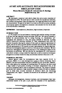
Guarantee GT mean GT max BE mean
500
Latency [cycles]
rate and fast system simulation possible, as proposed in the RAMP project [3] and shown by, for example, the BEE hardware emulation environment [5]. We would like to adopt this method and develop a simulator that requires a single FPGA for designs that are developed into RTL. This paper describes the method to sequentially simulate large parallel systems in one FPGA that normally would require multiple FPGAs. In this paper we use our Network-on-Chip as a case study for this simulator. The rest of the paper is organized as follows. In section 2 we describe the NoC that we would like to analyze. In section 3 we describe the three methods that are evaluated to simulate this network. In section 4 we describe the method that is used to simulate a parallel system sequentially. In section 5 we describe the implementation of this method onto the FPGA platform. In section 6 we show the speed improvements that are achieved by the FPGA method. In section 7 we discuss the simulator and conclude the paper in section 8.
400 300 200 100 0 0
0.02
0.04
0.06
0.08
0.1
0.12
BE load per PE [fraction of channel capacity]
0.14
Figure 1. Delay of the GT and BE packets vs. BE load for 6-by-6 network (queue size 2 flits) the arbitration compared to a standard wormhole router with VCs. The crossbar is asymmetric and has 20 inputs, one input for every queue, and five outputs that are directly connected to the router’s output ports. The access to the crossbar is arbitrated by 5 round-robin arbiters - one arbiter per crossbar output. This arbitration is sufficient, since a conflict can only arise when more than one queue contains flits destined for a same output port. Due to the predictable round-robin arbitration the router is able to handle guaranteed throughput (GT) traffic, if one single data stream is assigned per VC. Multiple best-effort (BE) packets can be assigned to the same output VC. For more details see [9]. Although the round-robin arbitration is deterministic and maximum latency per hop can be determined, the specific latency and timing of packets largely depends on the global behavior of the network. Figure 1 shows the result of the latency simulation for a 6-by-6 network that has been performed in SystemC. The graph shows how the latencies of the GT and BE messages depend on the offered BE load. For the GT traffic, the mean and the maximal latency of packets are given. When the offered BE load is low, the latency of the GT packets is smaller than the guaranteed (or allowed) latency. The reason is that the GT traffic utilizes the bandwidth unused by the BE traffic. Note: the latency of the GT packets is higher than the latency of the BE traffic because the GT packets are larger (256 bytes against 10 bytes for BE packets). With the increase of the BE load, the average and maximum latency of the GT traffic increases, but the maximum GT latency never exceeds the guaranteed latency.
3
Simulation of Network-on-Chip To simulate a whole network we examined three options: 1. VHDL 2. SystemC 3. An FPGA
For all options we modelled the NoC cycle and bit accurate. We started with a VHDL description, because, besides latency analysis, we are also interested in the area and power consumption of the NoC design after synthesis. A router implementation with with very good throughput and latency, might result in a very high power consumption. For example, we found that buffers require a relatively large amount of area and energy. So we would like to redo the simulation of Figure 1 with different buffer sizes and investigate what the effect of buffer size on performance and energy consumption is. For the latency and throughput analysis, we were hampered by the speed of the VHDL simulation (as is shown in section 6). Therefore, a SystemC model seemed a good approach with, as literature suggests, orders of magnitude speed improvements [11, 12, 14]. The SystemC simulations gave the first insights in the behavior of the network as is shown by Figure 1. However, to generate all the information that was required for this single graph we needed 29 hours of simulation time on a single Pentium 4. The attempt to simulate a NoC in an FPGA was inspired by the fact that an FPGA has a lot of internal storage, which enables updating a large number of registers in a single cycle. In our lab we have a platform available with a multiprocessor SoC. This SoC has an ARM processor which can communicate via a memory interface with a Virtex-II FPGA. This platform was used in our experiments. The method to simulate the network is described in the next section. In section 5 we describe the details of the FPGA simulator.
4
Sequential Simulation of a Parallel System
There are several ways to simulate a Network-on-Chip in an FPGA. The first idea was to instantiate the whole network in the FPGA including simple traffic generators, but initial synthesis tests showed a size limitation of approximately 24 routers in a Virtex-II 8000. These were results with a reduced data-path of 6-bit and without the network interfaces and simulation controllers. The two major bottlenecks were the number of CLBs and available number of tri-states in the FPGA. Therefore, a sequential simulator of the network was built. This simulator has another trade-off between hardware resource requirements and simulation speed. It required a small modification of the router VHDL-sources and an additional controller. It is very important that we can use (almost) unmodified VHDL sources as this will minimize the risk of errors between the synthesized hardware and the simulator. The only modification is the extraction of all registers in the design and their mapping on a memory position as explained in the next subsections. Up to now, the modifications are implemented manually, but automatic transformations should be possible. In this section we explain the methodology how to simu-
(a) Parallel representation
(b) Sequential representation
Figure 2. System with registered boundaries late a parallel system with cyclic dependencies in a sequential order. A network-on-chip can have multiple cyclic dependencies depending on the topology of the network and the design of the routers. The cyclic dependencies might cause changes of the inputs of a router after its evaluation in the sequential schedule. The change of input requires re-evaluations of the routers that corresponds to that input. We will explain the sequential simulation methodology using a 1-dimensional cyclic dependent example system. The method is also applicable for two and higher dimensional systems. We start with a cyclic system that can have an arbitrary evaluation order and no re-evaluation. This method is extended in section 4.2 to a partitioned system, where reevaluation is necessary due to the cyclic dependencies and its partitioning. The method is based on the two level timing model that was introduced in CONLAN [13]. In the explanation of the methodology we use system cycles (i.e. real time) and delta cycles (i.e. computation steps). A delta cycle is defined as a clock cycle in the sequential simulator that evaluates one function but does not advance the simulation time. A system cycle is a clock cycle in the simulated parallel system and corresponds to a real clock cycle. A system cycle consists of multiple delta cycles.
4.1
Sequential Simulation of Designs with Registered Boundaries
Figure 2a depicts a parallel system that consists of three combinatorial circuitries with functionality F1 (x), F2 (x) and F3 (x). The function Fi (x) may be equal or different to Fj (x). In the homogeneous NoC of our test case, all routers have the same functionality. The input of all Fi (x) comes from separate registers and the results go to separate registers. The circuitries are separated by registers. To simulate a system cycle of this system, we evaluate the three circuitries in an arbitrary sequential order. This increases the required time to simulate the system by a factor three, but reduces required hardware resources. All identical functions Fi (x), 0 Fj (x) can use the same implementation, denoted Fi,j (x). We change the logic of Figure 2a to Figure 2b, where
(a) Parallel representation
(b) Sequential representation
Figure 3. Possible static schedule all registers are mapped into a single memory. The func0 tions F1 (x), F2 (x) use implementation F1,2 (x) and F3 uses F30 (x). The set of implementations is replaced by H(x). In the memory, both the old and new version of the register values are stored (as depicted in the right part of the fig0 ure by R1..3 and R1..3 ). The order in which the circuitry is evaluated to calculate new register values can be arbitrary, because for all parts of the system a previously calculated register value is used at input to a combinatorial circuit to calculate the new register value. After all three functions are evaluated we should copy the new state to the current state of the registers and then a new system cycle can be started. In our system this copy action is performed by switching the offset pointer of the current state and new state. In the even system cycles the 0 registers R1..3 are the current state and R1..3 are the next 0 state. In the odd system cycles, R1..3 are the current state and R1..3 are the next state. Figure 3 depicts the execution example of simulating three system clock cycles.
4.2
Sequential Simulation of Designs with Combinatorial Boundaries
The approach described above is not completely suitable for our Network-on-Chip design as will be described in this section. To modify the original router design as little as possible, we would like to partition the design at the granularity of routers, as this is our basic element in the NoC. The router’s inputs and outputs are connected to neighboring routers via links (i.e. unbuffered wires). The previously described method requires that all output ports are registered. However, this is not the case in the NoC design. It is undesirable to change a given implementation for testing purposes, because rewriting the code might intro-
Figure 4. System with combinatorial boundaries duce faults and it is difficult. It requires repositioning of functionality, especially in a NoC where functionality might shift to the preceding or next router. However, in our case, it was not even possible without changing the functional behavior of the design. A solution is to re-evaluate the router’s state and output if one of its inputs has changed after its evaluation in the current system cycle. Re-evaluation is possible, because the router’s old state is available during the whole system cycle. Figure 4a depicts a system that represents our router architecture. The router cannot be described by a simple function Fi (x), because the router’s outputs depend, besides on its inputs, on its internal state. This can easily be solved by storing all internal registers in a memory as depicted in Figure 4b. The functionality of the router is then described by multiple functions (F (x) and G(x) in the example). F (x) and G(x) of a single router will be evaluated in parallel in the sequential simulation. Part of the inputs and the circuit F (x) of a router depends on the combinatorial circuit G(x) of the preceding router. In this case we cannot evaluate these routers in-order as in Figure 3. Any given sequence of routers will also give problems, because there is always a link that is read before it is updated by the preceding router. Changing the partitioning (e.g. group G(x) with F (x) of the next router) did not help, because no fully registered cross-section was possible and, as previously stated, it is generally undesirable. Therefore, we adapted Figure 2b to Figure 4b. For all internal registers we use the same mechanism as described in the previous section. For the links we have a separate memory, where every link has only a single memory position and not two as for the registers. Per memory position one additional status bit is stored. This bit indicates whether the last written value Has Been Read (HBR) from this link. Per router we group all status bits that corresponds to the links
# * $ "
"
!
"
# "
() # *
% &'
() # *
Figure 6. Schematic view of the hardware
Figure 5. Possible dynamic schedule that are connected to its input ports and output ports. If not all of these bits are valid the router is considered to be nonstable and has to be evaluated. A simple round-robin scheduler will decide which non-stable router has to be evaluated. If all routers are stable the network is considered to be completely evaluated and ready for the next system cycle. An example of three system clock cycles is given in Figure 5. Every system cycle is started by resetting all status bits to zero. Because all status bits are reset to zero at the start of a system cycle, it is guaranteed that all routers are evaluated at least once. This is necessary as a router might change its outputs independent of its inputs. After a router is evaluated all links that are connected to its input port will make their status bit one. Furthermore, if the router writes a value to a link, which is not equal to the current value in the memory, it will reset this link’s status bit to zero. The router that has this link as an input will become non-stable and has to be (re-)evaluated. In Figure 5 all values that are different from the current value are underlined. This happens in delta cycle (1,1);(1,2);(2,0);(2,1). In case of delta cycle (1,2) link 2 is updated, but had already been evaluated in delta cycle (1,0). In this specific case the HBR-bit changes from one to zero and router 0 has to be re-evaluated. In all other cases the updates of the links do not result in extra evaluation cycles as the HBR-bit was still zero and routers had to be evaluated anyway.
5
Implementation
The implementation of the simulator requires a hardware platform, an FPGA design and software. All three are described in this section.
5.1
Platform
Figure 6 depicts the general block scheme of the available platform with the most important components. The
SoC board contains a general purpose system-on-chip that is connected with 1 MB of on-board SRAM memory and lots of peripherals and connectors. One of the connectors connects the FPGA board with the SoC board. This connector contains a memory interface with a 32-bit wide data-bus and a 17-bit wide address-bus. All registers and memory of the FPGA design, via the memory interface, are available in the address map of the ARM9 processor. This makes it possible to control the FPGA and exchange data. Reading and writing the registers via the JTAG interface is significantly slower due to the narrow serial interface. The FPGA board itself does not have a separate off-FPGA memory and contains a Virtex-II 8000 FPGA. Any other platform that has a large FPGA and on-board SRAM memory available will be suitable for the simulations. The on-board SRAM is required by the general purpose processor that can control the simulation. This control is both generation of stimuli vectors as well as analysis of the results. This general purpose processor can either be implemented on the FPGA or, as in our case, a separate processor.
5.2
FPGA implementation
Figure 7 depicts the major blocks of the FPGA design. The design can be partitioned into two major parts. 1) The router part, that describes the logic of a single router and its stimuli interface. 2) The global part, which controls the FPGA and the Network-on-Chip that is simulated. If the system was heterogeneous, all the unique components needed to be instantiated once as depicted in Figure 2b. For the router we separated the combinatorial logic from the registers in the original router design. The inputs and output signals of all registers are concatenated into two memory words: old and new. The old word is the current state of the router and read from the memory. The new word is the result of the evaluation and has to be written into the memory after a delta cycle. The address of the memory corresponds to the router that is evaluated. This address is generated by the scheduler in the FPGA. Table 1 summarizes the width of the memory word. The number of routers in the network determine the depth of the memory. In the current implementation reading the values from memory takes 1 cycle. Evaluation of the combinatorial
Figure 8. Processes of the simulation
5.3
Figure 7. Schematic view of the FPGA design State
Registers
Input queues Router control and arbitration Links Stimuli interfaces
1440 bits 292 bits 200 bits 180 bits
Total
2112 bits
Table 1. Required registers per router logic and writing the result in memory takes another cycle. In total a delta cycle equals FPGA 2 cycles. The stimuli for the design are generated by software in the ARM9. We have chosen to generate the stimuli in software, because it is easier to define new tests and analyze the results in software. The disadvantage is the large amount of data that has to be copied from the ARM9 to the FPGA and visa-versa. The stimuli are buffered per virtual channel (VC) in cyclic buffers in the FPGA. The output values of the network are stored per router, and not per VC, in a cyclic buffer. The data in the buffers has a timestamp and can be read or written by the ARM9. The timestamps make it possible to store only valid data, which requires less storage space and less time to copy data. The cyclic buffers make it possible to run the simulation independently from the copying of data Of course, we have to prevent buffer under- and overrun, because it will influence the traffic in the NoC. Two extra cyclic buffers make it possible to log 1) the traffic of a specific link and 2) the access delay a flit notices before it enters the network. These two buffers cannot influence the traffic in the NoC.
Software
The simulation is completely controlled in software by the ARM processor. The software is partitioned in processes that communicate via cyclic buffers. All the processes can run in parallel and do not have dependencies. Figure 8 depicts the organization of these processes and what part of the hardware is involved. The top processes require only the ARM processor and the NoC simulation itself only requires the FPGA. The two processes that interchange data between the boards require both ARM and FPGA. Because each processes uses its own cyclic buffers, it only needs to be fired when data and free memory are available. The processes that only require the FPGA or ARM run in parallel, which tremendously reduces the simulation time. The simulation is performed in steps. We start with generating a routing information table. After all routes are determined, a loop is started that has five phases. 1) We start by generating the traffic for each node in a stimuli table. Any data pattern can be generated as the generation is done in software. The generation process uses a random number generator on the FPGA. Reading a 32 bit random number from the FPGA is noticeably faster compared to the standard rand() function in C. The generated stimuli table contains stimuli for at least x system cycles. 2) The generated stimuli have to be written into the input buffers of the FPGA. All input buffers are maximally filled unless no data is available. 3) After filling the buffers we start the simulation in the FPGA and evaluate x system cycles. This sequence of x simulated system cycles is called a simulation period. To prevent buffer underrun, the simulation period is fixed to the size of the VC stimuli buffers in the FPGA. The simulation in the FPGA needs to be started by software, but can run autonomously. 4) After a single simulation period, we have to empty the output buffers. We retrieve the data from the output buffers that we think are interesting for the analysis. For the buffers that are not interesting we can update the read-pointer, which empties the buffer. 5) After the data is retrieved from the FPGA it is analyzed and the desired statistics are stored. When the simulation is not finished we go to step 1 and generate extra traffic in the stimuli table. This makes it possible to simulate an arbi-
Block
CLB
RAM
Router Stimuli interface Network Random number generator Global control
1762 540 2103 2021 627
61 62 16 0 0
7053 (15%)
139 (82%)
Total
Table 2. FPGA resource usage (256 routers) Block VHDL SystemC FPGA average FPGA fastest
CPS 10-17 Hz 215 Hz 22 kHz 61.6 kHz
Table 3. Simulated clock cycles per second trary number of simulation periods which is not limited by the software or hardware. However, due to back-pressure in the network, not all generated data might have been written into the FPGA. To prevent the loss of this data and the potentially resulting undefined state of the stimuli, all unconsumed data will eventually be written into the FPGA. If the network is overloaded with traffic and it does not accept data on virtual channels for a longer time, this is reported to the user and simulation is stopped.
6
Results
In this section we describe the results of the simulator. The simulator is realized for a Xilinx Virtex-II 8000 FPGA and can simulate any size of network from 2 to 256 routers with 4 flit deep queues. Table 2 shows the resource usage of the simulator in the FPGA for a maximum network of 256 routers. From these results it is clear that the limiting factor of the design is the number of RAM-blocks that are used. It would be possible to simulate the design in smaller FPGAs, but it would reduce the maximum number of routers and/or the amount of state registers (e.g. queue depth) of the design. The router design is synthesized for a frequency of 6.6 MHz, which gives a delta cycle frequency of 3.3 MHz. This limits the maximum simulation frequency of the simulator to 3.3 ∗ 106 /36 = 91.6 kHz for a 6-by-6 network. No effort was made to increase this frequency, because it was sufficient for the first tests. The interface frequency is equal to the ARM frequency of 86 MHz, which makes it possible to copy data at a higher frequency. Table 3 shows the number clock cycles that can be simulated per second for a 6-by-6 NoC. The FPGA frequency depends on the generated network load and analysis techniques used. The difference between the theoretical maximum frequency and the measured frequency is caused by the software and copying data between ARM and FPGA.
Simulation step Generate stimuli (ARM) Load stimuli (ARM / FPGA) Simulation (FPGA) Retrieve results (ARM / FPGA) Analyze results (ARM)
% 45-65 % 10-20 % 0-2 % 5-15 % 5-40 %
Table 4. Profile information Table 4 shows the percentage of time that was spent in the different simulation steps and shows were we can improve the simulator. The percentages are given as ranges, because it depends on the type of simulations performed. The simulation itself is almost zero, because it runs in parallel with generation and analysis. The majority of the time is spent in the generation of the data. For complex simulations we see a large contribution by the analysis of the results. Those two functions could be optimized in software and there is no reason to increase the FPGAs delta cycle frequency. The minimum number of delta cycles per system cycle is equal to the number of routers of the NoC. In the extra delta cycles, unstable routers are re-evaluated as explained in section 4.2. The extra number of delta cycles mainly depends on the load that is offered to the network. The percentage of extra delta cycles is between 1.5 and 2 times the input load.
7
Discussion
The sequential simulation method described in this paper, can be used to simulate a parallel system on any sequential processor. The number of bits that can be updated in parallel in a delta cycle is much larger in an FPGA compared to a 32-bit processor. It can read and write a large number of bits in the available internal RAM. Furthermore, the FPGA has a large amount of logic, which can evaluate the functionality F (x), G(x), etc. in parallel. This also makes it possible to do both the evaluation and update of the registers in parallel. As shown by the case study a delta cycle can be evaluated in two FPGA clock cycles.
7.1
Flexibility of the FPGA simulator
The simulator on the FPGA is implemented as a homogeneous wormhole switching network with virtual channel flow control with a torus topology. The software on the ARM can change the network size from 1-by-2 to any 2 dimensional size with a maximum number of 256 routers. The maximum number of routers is limited by the amount of RAM that is required for the cyclic buffers and the router’s state. In the current simulator we have the same functionality for all the routers. It is possible to select a different router functionality depending on the position in the network. The limiting factor is the number of registers in the router. The
topology of a network can either be a torus or a mesh, which is determined by software. Other topologies are possible and only require a change in the addressing function of the link memories in the FPGA. The same technique used for the NoC simulator can also be used for testing other parallel systems on an FPGA. In particular systolic algorithms with many equal parts with a small state space. If the source-code for synthesis is available, it is relatively straight-forward to modify the code in the sequential framework. Heterogeneous systems can be supported as well, as long as the required extra combinatorial logic fits in the FPGA. In the NoC case, less then 10% of the logic resources are used for combinatorial circuitry of the routers. The registers can be mapped in the same memory space.
8
Conclusion
In this paper we described a simulation method for SoC designs on FPGAs. The method is especially suitable for parallel systems were lengthy cycle and bit accurate simulations are required. Those tend to require a considerable amount of time using a PC. Using an FPGA we are able to speed-up the simulation with a factor of 80-300 compared to a SystemC simulation without loss of accuracy and a small code difference with the original VHDL source code. We apply the modifications at RTL-level which makes it possible to run the simulator on any FPGA device. Although an FPGA cannot handle high frequencies, it benefits from its large internal memory bandwidth and parallel execution of many combinatorial circuitries. This enables us to update large parts of the system state in a single clock cycle. We used a homogeneous NoC to test the performance of the simulation. For this case study the largest amount of time was spent in generating stimuli and analyzing the results in software. A simple improvement by offloading the random number generation to the FPGA gave an extra 50% simulation speed. An extra factor 3 to 4 improvement of the software is necessary before the FPGA simulation itself or I/O with the FPGA becomes a bottleneck.
Acknowledgement This research is conducted within the Smart Chips for Smart Surroundings project (IST-001908) supported by the Sixth Framework Programme of the European Community.
References [1] http://www.smart-chips.com. [2] Open SystemC iniative OSCI, SystemC documentation. http://www.systemc.org, 2004.
[3] Arvind et al. RAMP: Research accelerator for multiple processors - a community vision for a shared experimental parallel HW/SW platform. Technical report, MIT, 2005. [4] L. Benini and G. de Micheli. Networks on chips: A new SoC paradigm. IEEE Computer, 35(1):70–78, January 2002. [5] C. Chang et al. Rapid design and analysis of communication systems using the bee hardware emulation environment. In Proceedings of 14th IEEE International Workshop on Rapid Systems Prototyping, pages 148 – 154, June 2003. [6] M. Coppola, S. Curaba, M. D. Grammatikakis, R. Locatelli, G. Maruccia, and F. Papariello. OCCN: A NoC modeling framework for design exploration. Journal of Systems Architecture: the EUROMICRO Journal, 50(2-3):129 – 163, 2004. [7] K. Goossens, J. Dielissen, O. P. Gangwal, S. G. Pestana, A. Radulescu, and E. Rijpkema. A design flow for application-specific networks on chip with guaranteed performance to accelerate SOC design and verification. In DATE ’05: Proceedings of the conference on Design, Automation and Test in Europe, pages 1182–1187, Washington, DC, USA, 2005. IEEE Computer Society. [8] A. Jalabert, S. Murali, L. Benini, and G. D. Micheli. xpipesCompiler: A tool for instantiating application specific networks on chip. In Design, Automation and Test in Europe (DATE), Paris, France, Februari 2004. [9] N. Kavaldjiev, G. J. M. Smit, and P. G. Jansen. A virtual channel router for on-chip networks. In Proceedings of IEEE International SOC Conference, pages 289–293. IEEE Computer Society Press, September 2004. [10] N. Kavaldjiev, G. J. M. Smit, P. T. Wolkotte, and P. G. Jansen. Providing QoS guarantees in a NoC by virtual channel reservation. In Proceedings of the International Workshop on Applied and Reconfigurable Computing (ARC 2006), Delft, the Netherlands, March 2006. [11] T. Kogel et al. A modular simulation framework for architectural exploration of on-chip interconnection networks. In CODES+ISSS ’03: Proceedings of the 1st IEEE/ACM/IFIP international conference on hardware/software codesign and system synthesis, pages 7–12, New York, NY, USA, 2003. ACM Press. [12] O. Ogawa et al. A practical approach for bus architecture optimization at transaction level. In DATE ’03: Proceedings of the conference on Design, Automation and Test in Europe, pages 176– 181, 2003. [13] R. Poloty and D. Borrione. The Conlan project: Status and future plans. In Proceedings of ACM-IEEE Design Automation Conference, Las Vegas, Nevada, June 1982. [14] T. Rissa, A. Donlin, and W. Luk. Evaluation of SystemC modelling of reconfigurable embedded systems. In Proceedings of Design, Automation and Test in Europe, volume 3, pages 253– 258, March 2005. [15] M. H. Wiggers, M. Bekooij, P. G. Jansen, and G. J. M. Smit. Buffer capacities for multi-rate real-time systems with backpressure. In Proceedings of CODES+ISSS’06, Seoul, Korea, October 2006. ACM. [16] P. T. Wolkotte, G. J. M. Smit, G. K. Rauwerda, and L. T. Smit. An energy-efficient reconfigurable circuit-switched network-on-chip. In Proceedings of the 12th Reconfigurable Architectures Workshop (RAW 2005), Denver, Colorado, USA, April 4-5 2005.