This data source will then issue look and manipulate commands to the controls and ... ability to look out the window in order to perform such actions as seeing ...
Using an Integrated Task Network Model with a Cognitive Architecture to Assess the Impact of Technological Aids on Pilot Performance
Christian Lebiere, Rick Archer, and Dan Schunk Micro Analysis and Design Boulder, Colorado Eric Biefeld Carnegie Mellon University Pittsburgh, Pennsylvania Troy Kelly and Laurel Allender U.S. Army Research Laboratory Adelphi, Maryland
Lebiere, C., Archer, R., Schunk, D., Biefeld, E., Kelly T. and Allender, L. (2003). Using an integrated task network model with a cognitive architecture to assess the impact of technological aids on pilot performance. In D.C. Foyle, A. Goodman & B.L. Hooey (Eds.), Proceedings of the 2003 Conference on Human Performance Modeling of Approach and Landing with Augmented Displays, (NASA/CP-2003-212267), 165-187. Moffett Field, CA: NASA.
This page intentionally left blank.
166
Using an Integrated Task Network Model with a Cognitive Architecture to Assess the Impact of Technological Aids on Pilot Performance
Introduction NASA’s System-Wide Accident Prevention Program (SWAP) has funded a number of different cognitive modeling approaches with the goal of developing techniques for predicting opportunities for human error in system designs and operational procedures. The project has been named the NASA Human Performance Modeling (HPM) project, according to Foyle, Goodman, and Hooey [2003]. Each of the modeling teams is developing a different approach to the same modeling problem. The current focus is on commercial aircraft approach and landing scenarios and the tasks the pilots must perform. The modeling compares pilot procedures using current technologies with procedures using augmented displays such as a synthetic vision system (SVS). Data to characterize the performance of pilots during four different approach and landing scenarios was collected by NASA via pilot participation in a part-task simulator [Goodman, Hooey, Foyle, and Wilson, 2003]. The four scenarios consisted of 1) a vectored approach, 2) a late reassignment of runways for the landing, 3) a missed approach, and 4) a mismatch of the terrain shown in the SVS and the out the window view from the cockpit. One of the modeling teams consisted of personnel from Micro Analysis & Design (MA&D) and Carnegie Mellon University (CMU). This paper describes the modeling approach used by the Micro Analysis and Design/Carnegie Mellon team and its application to one of the four scenarios.
Description of the Modeling Effort The approach that was used by the MA&D and CMU team to perform the approach and landing modeling was an integration of the Improved Performance Research Integration Tool (IMPRINT) and the Adaptive Control of Thought – Rational (ACT-R) cognitive architecture. It was agreed by project personnel from NASA and each of the modeling teams that the first scenario for all of the modeling teams would be a late reassignment of runways. There have been several sources of data for the modeling effort. The primary data source was a Cognitive Task Analysis (CTA) that was conducted as a separate effort in support of all of the modeling teams. The CTA was supplemented by a number of published papers and other background documents. In addition, videotapes of pilots flying approach and landing tasks in a NASA part-task simulator were provided. Following is a brief description of the two integrated modeling tools and what each provides for the integration. The results of the current year of the NASA HPM project from MA&D is a simulation model of an aircraft making its final approach and landing into an airport. The specific scenario that was chosen for this first effort was of an approach with a late reassignment of runways for the landing. The simulation model was built using the IMPRINT simulation tool [Archer and Allender, 2003]. The model built specifically represents an aircraft and its environment. Currently this environment includes the altitude at which the ground and runway can be seen from out the window and the air traffic control (ATC) communications. The model has been designed for more environment variables to be added as required. For the simulation of the aircraft, IMPRINT represents the autopilot as well as the physics of the aircraft. These aspects include the aircraft’s location in time and space, its deceleration, descent rate, and all physical changes in the aircraft including its landing gear, flap settings and air brakes. The model also includes the controls and displays of the aircraft including all autopilot functions. Represented in the model are the mode control panels, the primary flight display, the navigational display, and an out-the-window view. The model also handles all communication between the aircraft and air traffic control. With these controls and displays, the model is able to simulate how a plane will react in its environment when these controls and displays are manipulated. Currently the simulation is set up to work with a VNAV Path autopilot setting as
167
Using an Integrated Task Network Model with a Cognitive Architecture to Assess the Impact of Technological Aids on Pilot Performance
required for this first effort, but the model is capable of utilizing the other types of autopilot (e.g. Glideslope and Localizer) for future analysis. In order to perform successful analyses, this model requires an outside data source to act as the pilot (i.e. human in the loop or cognitive modeling software). This data source will then issue look and manipulate commands to the controls and displays of the model as required to perform the approach and landing tasks. The simulation model will terminate when the pilot switches off the autopilot for the manual portion of the landing. In this simulation, a model of the pilot was developed using the ACT-R cognitive architecture. Following the practice of decomposing complex behavior into a set of unit tasks, the ACT-R model is composed of a set of goals, together with the procedural and declarative knowledge necessary to solve those goals. The top-level goal is essentially a monitoring loop that repeatedly sets subgoals to check the settings of the various controls. Each of these subgoals typically requires acquiring the value of one or more environmental variables (e.g. speed, altitude, etc) by reading the instruments or looking out the window. A decision is then made as to what the desired control value is given those readings. If that value is different from the current control value, the appropriate action is performed to change that value. Decisions are made using either declarative or procedural means. For procedural control, a production rule is applied that supplies the control value given the environmental readings. This type of decision best captures crisp, symbolic decisions relying on precise values provided by instruments (e.g. “set flaps to 15 when speed is 200 knots”). For declarative control, instances are defined in declarative memory linking environmental readings to control values. Given a particular condition, the most relevant instance is retrieved from memory using a similarity-based partial matching mechanism, and the control value extracted from it. Multiple memory instances can also be retrieved using a mechanism called blending and a consensus control value extracted that best satisfies the set of instances. This control is similar to that provided by neural networks and best describes approximate, iterative adjustments as practiced in out-the-window flying.
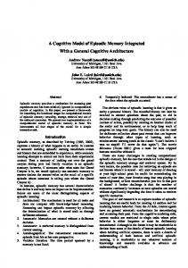
The Imprint Model The backbone of the IMPRINT simulation is a series of subnetworks representing the different aspects of the simulation (see Figure 1). When the IMPRINT simulation is started, the model starts in subnetwork 2, the Start/End Landing network. In this network all the initial communication takes place between ACT-R and IMPRINT. From the Start/End Landing subnetwork, the simulation starts the ACT-R Thought subnetwork, the Aircraft Environment subnetwork and the communication subnetwork.
Figure 1: Main IMPRINT Network
168
Using an Integrated Task Network Model with a Cognitive Architecture to Assess the Impact of Technological Aids on Pilot Performance
When the communication subnetwork is started, IMPRINT will schedule random communication tasks between the pilot and other pilots as well continually check for scheduled communication between the pilot and air traffic control. Inside the ACT-R Thought subnetwork, the main communication between ACT-R and IMPRINT takes place. With this communication, ACT-R decides what controls and displays to look at or manipulate. The Aircraft Controls and Aircraft Displays subnetworks represent the various controls and displays of the aircraft. In the Aircraft Environment subnetwork, IMPRINT updates the current state of the aircraft, its controls, its displays, and the environment itself every .1 seconds. This is a continual action until the end of the simulation.
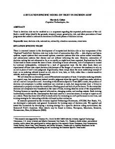
Figure 2: Aircraft Displays Subnetwork An aircraft’s displays are further broken down in the Aircraft Displays subnetwork (see Figure 2). In this subnetwork, the displays are separated into the main displays of the aircraft, specifically, the primary flight display, the navigational display, and the out the window display. It is important to point out that while there is no physical display specifically for out the window, the pilot has the ability to look out the window in order to perform such actions as seeing whether the ground is in sight or what the flap settings currently are at. The final level of the Aircraft Displays Subnetwork is the actual displays represented by tasks in the IMPRINT simulation. Figure 3 shows how each part of the Primary flight display is represented by a single task. During the IMRINT simulation, ACT-R will communicate to IMPRINT which display it would like the value for. IMPRINT will then start the task for the appropriate display and return that display’s current value. The information is then communicated back to the ACT-R Thought subnetwork located in the main IMPRINT network (see Figure 1).
Figure 3: Primary Flight Display Subnetwork
The ACT-R Model The ACT-R model cycles through six decisions. These decisions are the setting of the flaps, altitude, speed, lowering of the landing gear, setting of speed brakes, and engaging and disengaging the
169
Using an Integrated Task Network Model with a Cognitive Architecture to Assess the Impact of Technological Aids on Pilot Performance
autopilot. The model keeps cycling through these decisions until it either turns off the autopilot or misses the runway. The model uses two buffers, which mediate between ACT-R and the world (IMPRINT). The first buffer is LOOK. If ACT-R wants the value of some instrument or the setting of a dial, it uses the LOOK buffer to pose a query. The ACTION buffer is used to change the setting of a dial. The contents of both of these buffers are communicated to IMPRINT which then updates the LOOK buffer with the value stored within IMPRINT. Most of the decisions are based on either the aircraft’s speed or position. The Set-Flaps decision is based on the speed of the aircraft. The first decision is to look at the speed indicator. ACT-R then matches this speed against its speed flaps value in memory. After the flaps setting is retrieved, ACT-R looks at the current setting on the flap dial. If it is the same then it just goes to the next decision, in this case, dial altitude. If it is different it uses the ACTION buffer to update the flap setting. The altitude settings depend on which waypoint is next in the approach phase. Once again, ACT-R uses the LOOK buffer to “read” the waypoint indicator. It then “remembers” the correct altitude for the waypoint and if it is not already set, it communicates to IMPRINT to dial in the new altitude. If it is working correctly then the altitude should only be changed once for a waypoint position. The speed setting depends on the distance to the airfield. However, there is not a single reading which directly gives this data. Instead, ACT-R looks at the waypoint and then looks at the distance to waypoint. ACT-R then recalls the range of this waypoint to the airfield and computes the distance to the airfield. After this more complex set of productions, ACT-R then retrieves and, if needed, sets the speed in the same style as the previous decisions. The other decisions are done in a slightly different style. These are more like rule-based productions. Instead of being based on a set of memorized relations, the productions directly encode the decision point. For example, the abort-landing production checks to see if the distance to the runway is zero. If it is, it signals an abort and pops all the goals. The decide gear production checks if the distance to the runway is less than or equal to 15.0 miles. If it is, it lowers the landing gear. There is currently no production for raising the gear. The decision for the speed brakes is to compare the current speed to 145.0 knots. If the speed is less, the brakes are turned off. If the speed is greater than 145, the brakes are turned on. Like the other decisions, before performing the action a production checks the current setting and performs the action if the decision is not equal to the current setting. Unlike the landing gear, the current model could turn off the speed brakes, but given the current scenarios this never happens. The decision to disengage the autopilot depends on the visibility of the runway. ACT-R uses the outthe-window values to determine if the runway is visible. If it is then the next production will disengage the autopilot. When control returns to the top-level decision cycle, if the autopilot has been disengaged, ACT-R ends the simulation and signals success. If the autopilot is engaged, ACT-R cycles back to the set flap decision. A separate production responds to communications. The only effect it has is to take time away from the top-level control loop. This can cause the model to “miss” the runway.
170
Using an Integrated Task Network Model with a Cognitive Architecture to Assess the Impact of Technological Aids on Pilot Performance
Act-R/Imprint Protocol for the NASA HPM Project In order to successfully have communications between IMPRINT and ACT-R a protocol was set up so that each program responded correctly to the other program’s request. In this project IMPRINT acts as the aircraft and the environment affecting the aircraft. ACT-R acts as the pilot of the aircraft and decides which displays to look at and which controls to manipulate. The first step in creating this protocol was to develop a simple generic protocol that all ACT-R/IMPRINT links will use as a basis for developing intercommunications with each other. This generic protocol has three main areas: starting a model, ACT-R actions to be performed that take time, and ending a model. When an IMPRINT model that requires communication with an ACT-R model begins executing, an initial communication must take place between ACT-R and IMPRINT. This is done to ensure that both programs are synchronized in all areas of the model. This allows ACT-R to reset its current data as well as check to make sure that both IMPRINT and ACT-R are running the same version of the model. In the protocol, when the initial communication is made, the version numbers of both IMPRINT and ACT-R are exchanged; if there is a mismatch then the model will end. During the execution of an IMPRINT model, decisions and thought processes will need to be made by ACT-R that will take time. This time needs to be included inside the IMPRINT model, which holds the master simulation clock. The biggest obstacle with this communication is that during the time it takes for ACT-R to perform a thought or make a decision, an event in the IMPRINT simulation may occur. This event may cause ACT-R to perform differently (e.g. a person driving a car is thinking about changing the radio station when his/her tire blows out causing them the change their thought process from what radio station to listen to, to controlling the automobile). Likewise, ACT-R may decide to do nothing at the time but calculates a decision that may be made in the future (e.g. a driver of a car is deciding whether to change lanes or not, initially the driver decides to do nothing but ten seconds later decides to switch lanes). One thing to note is that the event may NOT cause ACT-R to perform differently (e.g. a person driving a car makes the decision to decelerate the car when the sun gets in their eyes, their decision stays the same). In the protocol, IMPRINT sends to ACT-R the current time of the model as well as the time in the model that the next IMPRINT event will occur. ACT-R, after performing its calculations, will reply back to IMPRINT with the new current time, the time that it will have another thought, and the action it has decided to perform. From this interaction, IMPRINT will decide what the next event will be as well as how much time it took ACT-R to make its decision. This interaction will occur many times in the model as the simulation is executed. The final generic protocol is a communication between IMPRINT and ACT-R that allows both programs to end correctly. The final event in the IMPRINT model is a communication between IMPRINT and ACT-R where IMPRINT sends over information to let ACT-R know that the IMPRINT simulation is ending and that this will be the final communication between the two programs. In this protocol, IMPRINT will send over a flag to ACT-R. ACT-R will then acknowledge that the flag has been received and end its model. IMPRINT will then end its simulation. Though the generic protocol was used as the basis, there were some changes to the basic interactions between IMPRINT and ACT-R as well as some additional interactions. The only generic protocol changed was the interaction between IMPRINT and ACT-R that occurred during the run. The added interactions include return information to ACT-R from IMPRINT, pilot/air traffic control communication, and some initialization of the model.
171
Using an Integrated Task Network Model with a Cognitive Architecture to Assess the Impact of Technological Aids on Pilot Performance
The main change to the generic protocol was to get more specific as to what actions the pilot was performing onto the aircraft. In this interaction, ACT-R is not only responsible for informing IMPRINT how much time it took for the pilot to make a decision on what to do, ACT-R also had to inform IMPRINT on what actions to take. The actions could be one of four things; the pilot could manipulate a control, look at a display, communicate with ATC or decide to do nothing. In informing IMPRINT of the action, ACT-R needed to provide IMPRINT with this specific information: what action to perform, what display or control the action was performed on, and the new setting of the control (if applicable). If the pilot was looking at a display, the action would default to a look action, but because the controls can be switches, buttons, or knobs, the correct action also needs to be performed on the control and there could be a possible setting (e.g. altitude setting). If the action was to communicate with ATC, ACT-R would also need to let IMPRINT know the type of reply the pilot was giving to ATC. Once ACT-R makes a decision as to what type of action to perform and where to perform it, IMPRINT needs to perform that action on the aircraft and update ACT-R as to the current state of the display/control. A real world example of looking at a display would be if a pilot decides to look at the current airspeed. In the real world, a pilot would look at the display and the pilot’s visual buffer would be instantaneously updated to the current speed. In the IMPRINT/ACT-R simulation, and when ACT-R (acting as the pilot) wants to look at a display, IMPRINT (acting as the aircraft and its displays) will need to return the value of that display to ACT-R to update ACT-R’s memory. In the model, IMPRINT would change the simulation clock time to include the time it takes for ACT-R to make the decision to look at a display and return the display’s current value. While this interaction will take time to perform in real world time, the simulation clock will not advance (and this interaction will be instantaneous). If a pilot wanted to manipulate a control (such as an altitude dial) then the pilot would take time to decide upon the new altitude, dial in the new altitude, and his visual buffer would be updated to the new altitude number. In the IMPRINT/ACT-R model, ACT-R would make the decision to change the altitude dial to a new value. IMPRINT would then advance the clock the time it took to make the decision to turn the dial and advance the clock the time it took to advance the dial. IMPRINT would then communicate to ACT-R the dial’s new value. Once again this will take up real world time, but in the simulation the update would be instantaneous. When a pilot is flying an aircraft, communications between the pilot and ATC will occur at various intervals. Communications fall into three different categories: a. b. c.
Communication to which the pilot should respond Communication to which the pilot should listen Communication that the pilot should ignore
During the simulation execution, various communications take place between ATC and the pilot. When a communication event occurs, IMPRINT will interact with ACT-R informing ACT-R that an ATC communication has occurred as well as the type of the communication. ACT-R then makes the decision during the course of the simulation as to if and when it should reply back to ATC in the form of an action. Appendix A contains details of the IMPRINT communication protocol with ACT-R. Appendix B contains details of the ACT-R communication protocol with IMPRINT.
172
Using an Integrated Task Network Model with a Cognitive Architecture to Assess the Impact of Technological Aids on Pilot Performance
Findings and Implications The model has many potential parameters, but we can aggregate them into five main ones, represented in figures 4-8 below. Each of these parameters corresponds to a separate module in the ACT-R architecture. Variations in those parameters can correspond to individual differences as well as changes in equipment or procedures. Four of the parameters are latencies (in seconds) which represent the time for the pilot(s) to perform procedural, visual, motor and auditory actions. Anderson and Lebiere, [1998] state that the other is ACT-R's Activation Noise value, which is a measure of the stochasticity of the model’s decision-making (see "The Atomic Components of Thought" for details). The first parameter is "visual speed", which represents the mean time for the pilot to look at an instrument and perceives its value. The next is "manual speed”, which is the mean time it takes to perform an action such as dialing in a new setting. The next is the “procedural speed” parameter which represents the time for a production rule to fire. The last is "aural speed”, which represents the time that the pilot spends listening to a communication before replying. The visual, manual and aural speed parameters are scaling factors, which vary depending on the precise perceptual, motor, or communication act. These values specify a random distribution to represent adequate between- and within-subjects variability. To test the model’s sensitivity to these parameters, their values were varied over a range of possible quantities. Since all five parameters had similar values we used the same test range for each parameter. Figures 4-8 below show the influence of the different pilot psychometric parameters on performance and their implications for cockpit design and procedures. The performance measure is performance correct landings as estimated by Monte Carlo runs of 20 samples for each parameter combination. The percentage of correct landings for default parameters was about 90%.
Percentage Correct Runs
100 80 60 40 20 0 .1
1
10
Visual Speed Parameter (sec)
Figure 4. Sensitivity to visual speed Figure 4 shows that pilot performance is very sensitive to the speed of visual shifts. The default value is 1 second, which corresponds to 90% correct landings. Improving the visual speed parameter by a factor of 2 yields perfect performance, which emphasizes the benefits of visual aids such as SVS that
173
Using an Integrated Task Network Model with a Cognitive Architecture to Assess the Impact of Technological Aids on Pilot Performance
can improve perceptual performance by combining multiple instruments onto a single display, thereby reducing the time taken by attention shifts between widely separated instruments or areas such as out-the-window scene. Conversely, impairments in visual speed lead to a rapid deterioration in performance.
Percentage Correct Runs
100 80
60 40 20 0 .1
1
10
Manual Speed Parameter (sec)
Figure 5. Sensitivity to manual speed
Figure 5 shows that pilot performance is also very sensitive to the speed of manual operations. The default manual speed is 2.5 seconds per action. Performance drops catastrophically when actions take significantly longer to perform, leading to total failure for a doubling of the action time. This factor supports the concept of division of labor between the pilot flying the aircraft and the pilot not flying, with one in charge of monitoring and decision-making and the other in charge of actually performing the actions.
Percentage Correct Runs
100 80
60 40 20 0 .1
1
10
Aural Speed Parameter (sec)
Figure 6. Sensitivity to communications Figure 6 shows that performance is highly sensitive to the overhead of communications. The default time to listen to a communication and decide whether it is relevant to performance is 0.5 second, which is quite small. However, even when reduced to still smaller values, a small risk of failure remains. The impact of communications is hard to eliminate because of the random nature of their
174
Using an Integrated Task Network Model with a Cognitive Architecture to Assess the Impact of Technological Aids on Pilot Performance
temporal distributions. Communications can occur at any time, including at critical moments in the control loop when even a small temporary disruption in attention can lead to failure. Increases in the number of communications or in the average duration of each communication (one can view the aural speed parameter as reflecting either) leads to a very rapid deterioration in performance. Figure 7 shows that performance degrades gradually with the activation noise that controls the stochasticity in the memory retrieval of decision instances. Interestingly, further reducing activation noise from its default value of 0.1 does not lead in the elimination of errors, because activation noise has been shown to serve a useful purpose in preventing systematic errors. The most promising remediation for this degradation is training to increase the number of decision instances (practice) and/or making the decision task more procedural.
100
Percentage Correct Runs
80
60 40
20 0 .1
1
10
Activation Noise (S)
Figure 7. Sensitivity to decision consistency
Percentage Correct Runs
100 80
60 40 20 0 .01
.1
1
Procedural Speed (sec)
Figure 8. Sensitivity to procedural speed Figure 8 shows that, because of the central nature of productions, performance degrades very sharply with the speed of the production cycle. Fortunately, there is a safety factor of 2 from the default production cycle latency of 50 msec before performance degradation occurs. This primarily reflects the fact that the production cycle is one to two orders of magnitude faster than the other ACT-R
175
Using an Integrated Task Network Model with a Cognitive Architecture to Assess the Impact of Technological Aids on Pilot Performance
modules, and that performance is therefore more limited by the speed of the other modules than by the production cycle itself. At this point, running the model with and without synthetic vision technology will produce very similar results since both conditions produce clear daytime vision of the terrain and runway. The important difference is that the average perceptual time is significantly reduced, on the order of a Look parameter value of about 0.5. This reduction occurred primarily because shifts of attention are greatly reduced because of the integrated display. This puts SVS operation in the range of safe, successful performance rather than the break point pictured above for conventional systems. We still need to more finely model additional savings achieved from the SVS display.
Future Directions Both the IMPRINT and the ACT-R models are currently being expanded to include all of the controls, displays, and autopilots in the B757 aircraft. This will allow us to model a number of different baseline and SVS flight scenarios. In addition, we have included the capability to quickly model other new cockpit technologies and their impact on pilot error and aircraft safety. In the upcoming year, we plan to expand our current models to include multiple cockpit scenarios with and without augmented displays.
Verification and Validation Given the dynamic nature of the timing of the decisions and actions captured in this modeling effort - both in terms of the internal cognitive environment as well as the external airport environment - the validation of the modeling work focused on the times associated with approaching and landing the aircraft. The validation process consisted of checking the predicted times associated with the aircraft activities against the times measured for the videotaped scenarios. The model predictions were based on inputs gathered from subject matter expert (SME) reports. The SME reports were used to estimate timing for all aircraft phases. These data were then fed into the IMPRINT model as environmental variables, which then were passed to the ACT-R model as cognitive variables. The interaction of these two models produced final model times as well as patterns of errors. The times were checked against the times measured from the supplied videotapes. Although no statistics were computed, the model outputs compared favorably with the times from the videotaped scenarios. Another source of validation is low-level behavioral data like duration and aggregate percentages of dwell times on various parts of the display as provided by eye-tracking equipment. Following a topdown modeling methodology, we initially chose to focus on the functional aspect of the model and the sensitivity of its overall performance to various architectural parameters, as described in a previous section, and to higher-level behavioral measurements as mentioned in the previous paragraph. While the model makes precise predictions about the amount and duration of times spent acquiring information from the environment (e.g. reading the altitude), it does not contain specific assumptions regarding which source that information is acquired from, e.g. from a traditional instrument or from the symbology of the SVS display. Such assumptions are required to make specific predictions regarding eye movements. However, as indicated by analyses of the eye tracking data, fundamental individual differences exist even within small subject populations (e.g. 3 pilots). Thus, one pilot might choose to rely primarily on traditional instruments, using the SVS system only to confirm their readings, while another might choose to rely on the SVS as its primary integrated source of information. To model both of these (as well as other) strategies, the model would have to be flexible enough to incorporate a learning component that would allow the model to settle on either of those strategies as a valid stable point in its search for information. We intend to refine our model to
176
Using an Integrated Task Network Model with a Cognitive Architecture to Assess the Impact of Technological Aids on Pilot Performance
incorporate learning of information-gathering strategies in order to generate eye movement predictions. This model will rely upon the Bayesian mechanism built into ACT-R to learn the utility of production rules, such as those selecting where to look to gather a piece of information.
Lesson Learned Our main advance in performance modeling consists of linking a discrete-event simulation tool such as IMPRINT to a cognitive architecture such as ACT-R. This combination works quite well in alleviating the shortcomings of each platform: the cognitive architecture provides a higher-fidelity representation of human performance than task network models, and the discrete-event simulation provides a transparent, scalable representation of the world to interact with the human performance models. We learned that, in order to accurately model the behavior of the pilot and to be able to predict errors that the pilot will make, we need as much specific information as possible, especially in terms of the response of the aircraft to various commands. Ideally, we would like to hook our ACT-R model directly to the NASA part task simulator. In this way we could ensure that we present the model with the full rigor of the task and replicate exactly what the pilots did in the experiment.
177
Using an Integrated Task Network Model with a Cognitive Architecture to Assess the Impact of Technological Aids on Pilot Performance
References Archer, S. and Allender, L. "New Capabilities in the Army's Human Performance Modeling Tool," Proceedings of the Military, Government, and Aerospace Simulation (MGA 2001) Conference, pg 22-27, editor Michael Chinni, 2001. Anderson, J. and C. Lebiere (1998). The Atomic Components of Thought. Mahwah, NJ, Lawrence Earlbaum Ass. Box, D. (1998). Essential COM. Reading, MA, Addison Wesley Longman, Inc. Foyle, D.C., Goodman, A., and Hooey, B.L. (2003). An overview of the NASA Aviation Safety Program (AvSP) System-Wide Accident Prevention (SWAP) Human Performance Modeling (HPM) element. In Conference Proceedings of the 2003 NASA Aviation Safety Program Conference on Human Performance Modeling of Approach and Landing with Augmented Displays, (David C. Foyle, Allen Goodman & Becky L. Hooey, Eds.). NASA Conference Proceedings NASA/CP-2003-212267. Fujimoto, R. M. (2000). Parallel and Distributed Simulation Systems. New York, NY, WileyInterscience. Goodman, A., Hooey, B.L., Foyle, D.C., and Wilson, J.R. (2003). Characterizing visual performance during approach and landing with and without a synthetic vision display: A part-task study. In Conference Proceedings of the 2003 NASA Aviation Safety Program Conference on Human Performance Modeling of Approach and Landing with Augmented Displays, (David C. Foyle, Allen Goodman & Becky L. Hooey, Eds.). NASA Conference Proceedings NASA/CP-2003-212267.
178
Using an Integrated Task Network Model with a Cognitive Architecture to Assess the Impact of Technological Aids on Pilot Performance
APPENDIX A IMPRINT COMMUNICATION PROTOCOLS Communications between ACT-R and IMPRINT are made using External Model Calls (EMCs). EMCs utilize Microsoft’s Component Object Model (COM) capability to allow two or more programs to share information. When an IMPRINT model is loaded into Goalsaint, its discrete event simulator, a communication link is created between the Imprint model and ACT-R. Every time a variable is sent between ACT-R and IMPRINT, the software receiving the variable must send out an acknowledgement that the variable was received (e.g. When ACT-R receives a variable from IMPRINT, ACT-R must return to IMPRINT a value of one to acknowledge that ACT-R did in fact receive the variable from IMPRINT) During model execution, Goalsaint will execute model commands that send variable information to ACT-R. ACT-R will then take this information and make the appropriate decision as to what the pilot will decide to do next. The following is a list and explanation of each type of External Model Call made in the NASA HPM Imprint model. EMC Definitions: EMCStart Purpose: Initialize contact between ACT-R and IMPRINT. Vars Sent to ACT-R VersionNum – The current version of the IMPRINT analysis EMCFlag – Flag representing which EMC call is currently being made Vars Returned to IMPRINT
ACT-RVersNum – The current version of the ACT-R analysis EMCEnd Purpose: End contact between ACT-R and IMPRINT Vars Sent to ACT-R ModelDone – Variable sent to ACT-R indicating the Model is ending EMCFlag – Flag representing which EMC Call is currently being made
Vars Returned to IMPRINT None – No variables are returned, this EMC call is just a message to ACT-R that IMPRINT will be ending the simulation and severing the communications link. EMCAction Purpose: Communication between ACT-R and IMPRINT, in which ACT-R as the pilot decides what control or display it will look at or manipulate.
179
Using an Integrated Task Network Model with a Cognitive Architecture to Assess the Impact of Technological Aids on Pilot Performance
Vars Sent to ACT-R CurrentTime – The current simulation time ResumeBy – The time at which an event in IMPRINT may occur EMCFlag – Flag representing which EMC call is currently being made Vars Returned to IMPRINT CurrentTime – The current simulation time (Note: This time will include the time it took for ACT-R to make its decision, simulating the time it would take a pilot to make a decision) ResumeBy – The time at which ACT-R may make another decision ActionSet – The setting value of the control being manipulated, not all controls have specific settings (e.g. An altitude dial needs to have an associated dial value, and autopilot button just needs to be pushed) ActionCon – What control/display is being looked at/manipulated Action – What action is being performed on the control/display (e.g. look, push button, switch switch, etc) EMCComm Purpose: At various times during a flying simulation, there will be various communications being broadcasted, either randomly or at certain periods of a flight. The EMC call occurs to represent these communications. The pilot then has the option to respond at any time during the flight in the EMC call EMCAction. Vars Sent to ACT-R CommType – The type of communication message that was sent (e.g. Runway to land on from ATC, Chatter between aircraft, etc) EMCFlag – Flag representing which EMC call is currently being made Vars Returned to IMPRINT None – No variables are returned to IMPRINT, the approach taken is that in a real situation, the pilot may receive the communication right away but may not respond immediately. Pilot response is taken into account in the EMCAction call. This way there is the opportunity for a pilot to prioritize when to respond. EMCInit Purpose: To initialize ACT-R with the beginning settings of the IMPRINT model. This EMC works in conjunction with another EMC call named EMCInitUpd. This EMC call and the EMC EMCInitUpd are made at the very beginning of model. These calls occur many times and no simulation time will be used. What happens is IMPRINT asks ACT-R what control/display value it needs; ACT-R returns the control/display that it doesn’t have an initial value for, and then IMPRINT returns the value of that control/display. Vars Returned to IMPRINT ActionCon – The control/display that ACT-R needs the initial value for InitEMC – A flag indicating ACT-R has all the initial display/control values it needs
180
Using an Integrated Task Network Model with a Cognitive Architecture to Assess the Impact of Technological Aids on Pilot Performance
Vars sent to ACT-R EMCFlag – Flag representing which EMC call is currently being made EMCInitUpd Purpose: To initialize ACT-R with the beginning settings of the IMPRIN model. The EMC returns the initial values to ACT-R the control/displays that ACT-R needs. Vars Sent to ACT-R CurDisplay – The current control/display that ACT-R asked for DisplayVal – The value of the control/display EMCFlag – Flag representing which EMC call is currently being made Vars Returned to IMPRINT None – IMPRINT assumes all variables and there values were successfully sent to ACT-R and do not need any return variables to continue.
181
Using an Integrated Task Network Model with a Cognitive Architecture to Assess the Impact of Technological Aids on Pilot Performance
APPENDIX B ACT-R COMMUNICATION PROTOCOLS While IMPRINT and ACT-R are both simulations, they use different representations for the world. Within IMPRINT, all state information is represented as numbers or arrays of numbers. These numbers are stored using global variables. The general way to send or receive data from IMPRINT is by using a COM feature built into the system. ACT-R’s basic representation is memory chunks and production rules. However, since it is built in LISP a sophisticated user can interface with the system in a variety of ways. By compiling the system in Allegro Common LISP we used the provided OLE libraries to interface IMPRINT through with Microsoft’s COM. COM Layer When IMPRINT starts to run a model it launches and connects to an application. This is done using COM’s Client-Server protocol [Box, 1998]. Before an application can be launched by IMPRINT, it must be recorded in Microsoft Window’s Registry. This is done by first opening the ACT-R application and executing the LIA function (register-server). This needs only to be done once for each installed platform. When the application is started LIA will automatically load the file “sys:liacom.fasl”. This file contains the necessary COM functions. This file will start a COM server into which IMPRINT can link. The name of the application and server name is defined by IMPRINT. For the current NASA HPM project, the name chosen by MA&D is “EMC_NASAHPM”. With ACT-R, the variable ApplicationName is set to “EMC_NASAHPM”. The COM server name is constructed from the application name. IMPRINT has implemented several COM methods. These methods allow an outside application to communicate with IMPRINT. The eight that send and receive data are currently used in LIA. The relevant COM methods are: (4) ReceiveIntVariable (Name: String; Value: Integer) (5) ReceiveFloatVariable (Name: String; Value: Float) (6) ReceiveIntArrayVariable (Name: String; Value: Integer; Index: String) (7) ReceiveFloatArrayVariable (Name: String; Value: Float; Index: String) (8) SetIntVariable (Name: String; Value: Integer) (9) SetFloatVariable (Name: String; Value: Float) (10) SetIntArrayVariable (Name: String; Value: Integer; Index: String) (11) SetFloatArrayVariable (Name: String; Value: Float; Index: String) The first four are used to send data from IMPRINT to ACT-R while the remaining four are used to send data from ACT-R to IMPRINT. IMPRINT sends the variable name and value to ACT-R. The Name is the print name of an IMPRINT global variable. The Value is the value of the variable while the Index is the index into the array. Even if the data is stored within an array, the data is sent one element at a time. For the Array methods, the index is a string of the form “I J K”. For a one-dimensional array the index would be “I 0 0”. The IMPRINT modeler specifies the name of the receiving application. The modeler then decides when and which variables to transmit over the COM link. Incoming data will transparently update IMPRINT’s variables.
183
Using an Integrated Task Network Model with a Cognitive Architecture to Assess the Impact of Technological Aids on Pilot Performance
However, ACT-R has a different point of view. Instead of all data being numbers or array of numbers, ACT-R uses symbols and collections of objects with slots that hold the data. More on how LIA assist in the translations of view points will be discussed later. External Model Call (EMC) Layer On top of the COM layer MA&D has developed the EMC protocol. An EMC is a type of remote procedure call (RPC). An IMPRINT integer variable is used to communicate the remote procedure. In the NASA HPM domain, this variable is “EMC_Flag”. The LIA variable *Emc-Name* is set to the appropriate string. For any EMC, IMPRINT first sets the EMC_flag to an integer that corresponds to the remote procedure call. It then sends the arguments using the four RECEIVE COM methods. It then sends the value of EMC_flag using the ReceiveIntVariable method. Any return arguments are transmitted to IMPRINT by the remote procedure using the SET COM methods. The remote application (ACT-R) must first store the data from the COM methods. For any array, this would be one COM method for each element. When the ReceiveIntVariable is invoked with the Name parameter equal to Emc-Name, ACT-R must lookup the corresponding function and apply it to the appropriate arguments. Any values returned by the function, must be associated with their corresponding IMPRINT variable names and sent back using the correct COM methods. Unlike shared Variables, most of the joint IMPRINT/ACT-R simulations use less than ten EMCs. Since LIA is implemented in LISP, we created a Defemc macro. The macro is similar to the Common LISP Defun macro, which is used to define functions in LISP. Besides defining the top level of an EMC function, the Defemc defines the argument passing and codes needed to dispatch an EMC. (DefEMC (name code return-attributes*) ((var attribute)*) {code}*) (defemc (emcstart 1 |ACT-RVersNum|) ((version |VersionNum|)) (assert (= version *IMPRINT-Model-version*) () “Version does not match”) (lia-reset) (if (zerop *trial*) (initiaize-parameters (nth *subject parameters*))) ;; Speed Altitude Distance Flap (setq *initialize* ‘(speed altitude flaps) *initial-values* nil) *ACT-R-Model-version*) In the previous example “emcstart” is the name of a LISP function that is dispatched when the EMC code is 1. This function takes one parameter “version” that is set from the attribute “VersionNum”. The value returned is sent to IMPRINT via the attribute “ACT-RVersNum”. The body is the LISP code, which executes this EMC. Attributes LIA needs to store and decode values. After creating the low level COM link in LISP the desire to generalize the use of IMPRINT variable names as data labels and the mapping of numbers into symbols was the impetus for LIA. For each IMPRINT variable that is used as a COM label an Attribute is defined. An Attribute is a data structure, which stores the data and tracks the parameters needed for data translation and transmission. The slots within an attribute include: (4) Name, the IMPRINT variable print name.
184
Using an Integrated Task Network Model with a Cognitive Architecture to Assess the Impact of Technological Aids on Pilot Performance
(5) Value, the latest decoded value or if the IMPRINT variable is an array then a LISP array of decoded values. (6) Type, the standard types are Integer, Real, Boolean, and Enumeration. Other domain specific types can be used. (7) Dimensions, a list of zero to three integers representing the dimensionality of the value. If the list is nil then the data is directly stored in the value slot. Otherwise, an array with the specified dimensionality is stored in the value slot. (8) Fill, if the value is an array and not all of the array values are initialized then the fill value is used to pad out the array. The LIA function Find-Attribute takes either a string or a symbol and returns the attribute with the corresponding name. If its input is an attribute then it just returns the attribute. Besides the normal slot accessors, the setfable function Attribute is defined. Its parameters are (name &rest indexes). The attribute is looked up using find-attribute. If the indexes are nil then its value is returned. If there are indexes then the specified array element is returned or set. The function Send-Attribute takes an attribute and transmits its value to IMPRINT using the appropriate SetVariable COM method. Before the attribute is sent, its value is encoded as an integer or float. If the attribute is an array, all the elements are sent. The function Update&Send-Attributes takes a list of attributes and a list of values. First, the attributes are updated using the corresponding values. Then the function Send-Attribute is mapped over the list of attributes. The function Update-Attribute deals appropriately with arrays. When a ReceiveVariable COM method is invoked, it stores the decoded value into the attribute. The decoding and encoding of values use the generic functions Encode-Value and Decode-Value. The parameters for both of these generic functions are value and type. Type is a symbol for which specialized methods are written. For example: (defmethod encode-value (value (type (eql ‘boolean))) (if value 1 0)) defmethod decode-value (code (type (eql ‘boolean))) (not (zerop code))) By writing the two defmethods a new LIA data type can be added. In the NASA domain there existed IMPRINT variables whose data type depended on which display was being examined. Therefore, the data type “Display” was added by simply adding: (defmethod decode-value (code (type (eql ‘display))) (decode-value code (enum-bridge (attribute ‘curdisplay)))) (defmethod encode-value (value (type (eql ‘display))) (float (encode-value value (enum-bridge (attribute ‘curdisplay))) 0.0)) to the glue.lisp file for the NASA code. These methods look up the data type of the attribute and recursively call themselves with that particular data type. Since the number of variables is large in a model, the attributes are defined in an Excel sheet. This is converted into tab-delimited file and loaded using Load-Table. Load-Table (file loader layout &key (header 1) (delimiter #/tab) (trim whitespace)) File is the name of the file to be loaded. Loader is a function that processes a row of the table. Layout is a list of column numbers. The data corresponding to the layout list is passed to the loader function. The keyword argument header tells the load-table function how many rows to skip before processing (1 by default). Delimiter is the character that separates the columns of the table (tab by default). Trim is a sequence of characters that are removed for each field (white spaces by default).
185
Using an Integrated Task Network Model with a Cognitive Architecture to Assess the Impact of Technological Aids on Pilot Performance
The code in the file nasa/code/glue.lisp that loads the attributes is: (clear-attributes) (load-table "variables.txt" 'load-attribute '(0 1 5)) Load-attribute takes Name, Type, and Dimensions as parameters. It creates and stores in the attribute table the corresponding attribute. Note the layout ‘(0 1 5). The Excel sheet contains additional columns that are used by MA&D as documentation. Enumerations While IMPRINT uses numbers, ACT-R models use LISP symbols. For the NASA domain, IMPRINT uses codes to represent various discrete items. For example, Flaps are code 600, while the views out the cockpit window are codes 300 – 307. When ACT-R set the flaps the rule was written as (isa action control flap dial =setting). The LIA layer would transparently translate the symbol flap to the integer 600. Similarly when ACT-R rules looked out the window to see if the runway is visable the symbol outwindow-runway would be encoded as 305. To simplify the domain code needed to link IMPRINT and ACT-R the conversions of these domain codes to symbols was integrated into the LIA layer. The LIA layer calls the mapping of codes to symbols enumerations. Since the set of enumerations is domain specific and numbers almost a hundred for the NASA HPM domain, an Excel file was created to initialize the enumerations table. Both the attributes and enumerations are transmitted via email using an Excel file. The enumeration sheet is also saved as a tab delimited file. It can then be loaded into ACT-R using the form: (Load-Table “enumerations.txt” ‘load-enumeration ‘(0 1)). Another standard data type supported by the LIA layer is boolean. For boolean variables the values 1, 0 are mapped to T, nil. LIA Functions Synchronization Since both ACT-R and IMPRINT are simulations, they have to be synchronized. We use a conservative paradigm [Fujimoto, 2000]. One to three EMCs are used to send synchronization events between ACT-R and IMPRINT. In the NASA HPM domain the only synchronization EMC was EMCAction. When these events are sent the attribute “Current” is used as the time stamp for the event. The attribute “ResumeBy” is effectively a “null event” which allows either ACT-R or IMPRINT to advance its internal simulation clock. A null event as defined by Distributed Simulation Systems (DSS) only passes a timestamp. It is a guarantee that the sending system will not produce any messages (events) that will need to be processed until the clock reaches the timestamp. LIA has several functions that are useful for implementing the synchronization scheme. The first is LIA-Run. This function takes two arguments Current and ResumeBy. It will run ACT-R until either ACT-R halts or the agreed upon time is reached and control needs to return to IMPRINT. LIA-Run returns new values for Current and ResumeBy. These values are to be returned to IMPRINT to complete the synchronization handshake. LIA-Run can be controlled with several global variables. The variable LIA-Quantum is used as a temporal lookahead in the synchronization paradigm. If the ACT-R rules set the variable *LIAWaitp* or if there is no goal then the ACT-R clock will be set ahead to the next IMPRINT event. Quitting-Time is used to set a maximum time for the simulation to complete.
186
Using an Integrated Task Network Model with a Cognitive Architecture to Assess the Impact of Technological Aids on Pilot Performance
When an IMPRINT model that requires communication with an ACT-R model begins executing, an initial communication must take place between ACT-R and IMPRINT. This is done to ensure that both programs are synched up in all areas of the model. This allows ACT-R to reset its current data as well as check to make sure that both IMPRINT and ACT-R are running the same version of the model. In the protocol, when the initial communication is made, the version numbers of both IMPRINT and ACT-R are exchanged; if there is a mismatch then the model will end. The function LIA-Reset is used to initialize a new run in a multi-trial simulation. It resets ACT-R’s model, assigns an offset to ACT-R’s clock and tracks which run and trial the simulation is performing. This function is usually called by EMCStart. The third generic protocol is a final communication between IMPRINT and ACT-R that allows both programs to end correctly. The final event in the IMPRINT model is a communication between IMPRINT and ACT-R where IMPRINT sends over information to let ACT-R know that the IMPRINT simulation is ending and that this will be the final communication between the two programs. In this protocol, IMPRINT will send over a flag to ACT-R. ACT-R will then acknowledge the end of the simulation. IMPRINT will then end its simulation. The function Signal-Done can be used in an ACT-R’s model to end the simulation and set a completion code. While the function, LIA-WrapUp is used to clean up any pending goals in ACT-R. LIA-WrapUp is usually called by EMCEnd which should be the last EMC sent from IMPRINT to ACT-R. After running the simulation, IMPRINT will disconnect from the COM server started by ACT-R. If the LIA variables *auto-exit* is true then the ACT-R application will terminate itself in about 3 seconds after the disconnect.
187