Johannesburg, South Africa ... particularly useful for software development is the port-based modeling ... properties, methods and custom attributes) of a class.
International Journal of Innovative Computing, Information and Control Volume 1, Number 4, December 2005
c ICIC International °2005 ISSN 1349-4198 pp. 609—623
USING AN OBJECT ORIENTED CALCULATION PROCESS FRAMEWORK AND NEURAL NETWORKS FOR CLASSIFICATION OF IMAGE SHAPES Lukasz A. Machowski and Tshilidzi Marwala School of Electrical and Information Engineering University of Witwatersrand Johannesburg, South Africa { l.machowski, t.marwala }@ee.wits.ac.za
Received January 2005; revised May 2005 Abstract. Modern software systems are perpetually becoming more complex. Machine vision is a field that demonstrates this concept clearly. Shape classification, which is a part of machine vision, has both high and low level image processes in it. This paper presents a framework that brings the definition and implementation of complex calculation processes into the object oriented paradigm. Defining processes in this manner assists in concurrent development by groups of people. The paper describes how the shape classification process is implemented in the framework. Results of a C# implementation are compared to a procedural implementation in Matlab. The timing requirements for the various stages of the shape classification process are evaluated. The object oriented framework is well suited to high level machine vision concepts while the procedural paradigm is well suited to low level tasks such as edge detection. The C# implementation of the shape classifier demonstrates the maintainability and reusability of the framework. It has 26 out of 33 process classes using inheritance for specialization or composition for defining sub-processes. This framework is well suited to machine vision processes. Keywords: Object oriented, Calculation process framework
1. Introduction. The complexity of modern software projects is perpetually increasing because of the growth in computational power available. Modern software engineering techniques allow us to comprehend these large software systems and to manage the complex requirements of a user’s application [1]. There is a tendency for users to demand more intelligence from their software and this typically requires the complexity of the calculation process to be increased. Up to now, software engineering techniques have been assisting us in designing, reusing and maintaining the large software systems. What is lacking is the focus on developing methods for writing complex calculation processes which are necessary for increasing the overall intelligence of the system. An example where this is the case is in the field of machine vision. There are many different features of an image which can be used for classifying objects and these include color, texture, motion, context and shape [2-4]. Shape information is used extensively for classification of objects in vision systems and is an important visual feature [5,6]. There are also several methods that can be used for performing the classification of the object and these include similarity distance measures, template matching, index calculation, hashing, maximum likelihood, clustering and neural network classification [4,7]. There are many advantages 609
610
L. A. MACHOWSKI AND T. MARWALA
of using neural networks and these include being able to train the system using example images and having superior generalization abilities when compared to other classification techniques. This paper presents the design and implementation of a shape classification system in an object oriented (OO) calculation framework. It allows engineers and scientists to define complex calculations by making them into calculation objects. This aids in the effective design and sharing of calculation processes between teams of experts because of the type checking and other error-eliminating features of modern compilers. The class definitions required to make the calculation objects also ensure that they have precisely defined interfaces and their behavior is predictable. This framework is then evaluated by implementing a shape classification process in an object oriented manner. 2. Background. 2.1. Process frameworks. A process can be defined as a structured and measured set of events occurring over time to produce a specified output [8-10]. From the literature, it becomes evident that the process deals with how the output is derived and not what output is derived. This has several implications. The first is that the process is made up of smaller units of work that have clearly defined inputs, outputs and behaviors. The second is that the order in which each work unit is done is just as important as what work unit is done. The relationships that relate and constrain these sub-processes are most important to defining the process [8,9]. The role of a process is to convert given inputs into useful outputs [11]. Reuse is a key issue for handling complexity [1,10]. Process reuse involves identification, selection, understanding and awareness of suitable model-fragments [9] or partial-models [1] to reuse as templates. Identifying process templates is usually a tedious and difficult task and often leads to redevelopment of the entire process or using the same template for most of the processes [9]. 2.2. Object oriented modeling and simulation. There already exist many modeling paradigms and commercial simulation packages [12,13]. A modeling paradigm that is particularly useful for software development is the port-based modeling paradigm because of the types of calculation processes that are typically performed in software. A port defines an intended interaction (in the form of a signal or energy) between a sub-process and its environment [12]. A process is made up by connecting the ports of smaller subprocesses together. Signals are used for the interactions between processes in a block diagram. The drawback with this is that the user is responsible for determining the causality of the model [11,12]. The Object Oriented Modeling Paradigm was invented by Hilding Elmqvist as part of his PhD dissertation [14,15]. This paradigm shares many of the advantages of object oriented programming while allowing one to model a-causal systems. Representing processes as classes enables the modeling of process structures with work breakdown (decomposition) and control-flow dependencies (associations) [9]. Associations express how classes can be related in building the global system [8]. The OO modeling and simulation concept has great intuitive appeal because the notion of interacting objects is similar to that of real-world experiences [10].
CLASSIFICATION OF IMAGE SHAPES
611
The Unified Modeling Language (UML) has officially become the standard for object oriented analysis and design [9,16]. Often, classes and associations are stereotyped as process model primitives. The lack of first class process modeling primitives is a major limitation of UML, particularly with associations, which have to be implemented by references [8]. The Object Management Group (OMG), who are responsible for defining and maintaining UML, are focusing on model driven architectures and are showing an interest in model-driven process support [9]. Object Oriented process models decrease the conceptual gap between process modeling and software implementation [9] while demonstrating that OO can be used successfully for modeling software processes [8]. 2.3. Reflection. Reflection is an advanced feature of the .NET framework that gives runtime access to the metadata of a program so that it can gather information about its types. This includes the ability to get information about all the members (fields, properties, methods and custom attributes) of a class. Reflection also allows one to build new types at runtime. Reflection is typically used to create typed browsers; for finding fields to persist in serialization and for building symbol tables in compilers [17]. Because fields and properties are treated differently (properties being more powerful than fields), reflection is also useful for finding out which members of a class are fields and which are properties. 2.4. Machine vision and image processing. Getting a machine vision system to recognize objects from images is a difficult and well studied problem [4]. The ability of humans to segment, classify and recognize objects with relative ease makes it a sought after ability for vision systems. Being able to sense the environment using visual information has many applications in the commercial, industrial, medical and military fields. Machine Vision is used to understand the content of images while image processing enhances the ability to achieve machine vision [18]. Image processing can be partitioned into three levels and each level has a specific output [18]: • Low-level: an improved image, such as one with reduced noise. • Mid-level: a two dimensional data structure, such as the result of edge detection. • High-level: a data structure describing the content of the scene. Machine vision is the computer analysis of images with the intent to discover what information the images contain [18]. Recognition of features is the core of machine vision and it relies on finding suitable representations in order to find these features. Once an adequate representation has been achieved, pattern and feature analysis are employed to analyze the image for information content [18]. According to Erman and Lesser [19], it is impossible to construct a successful machine vision system without careful attention to issues of system engineering. These issues include maintainability and configuration control, human engineering, performance analysis, and efficiency. If we include reusability in this list then we notice that it resembles the problems faced by software developers before the advent of the object oriented software paradigm.
612
L. A. MACHOWSKI AND T. MARWALA
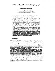
2.5. Shape representation. Representation is the process of determining a description for an object or region [18]. There are several techniques for representing shape information [3,5,6,18,20-22] and many make use of the boundary of a segmented object to extract the shape information. The information can then be transformed to retrieve shape descriptors for classification of the shape or retrieval from a database [2,23]. It is desirable to have a representation that is easily computed and simple to interpret, especially if the system is to be implemented as an embedded system. One method of representing shape is the Freeman Chain Coding which encodes the directions taken while moving from pixel to pixel around the shape boundary [18]. Problems with this method occur when the boundaries are not smooth or when they are fragmented [18]. The advantage is that the chain coding is an efficient method for storing the shape information. Other methods include fitting line segments, B-Spline representation, Fourier descriptors and Autoregressive models [24]. If the pixels of a 2D image representing a shape are processed into a single dimension then we have what is known as a signature [18]. The polar representation is an example of a signature [20]. Acquiring the polar representation of a shape with respect to the centroid is an attractive approach because it is easily calculated and only requires the boundary information [21]. The major problem with this is that the centroid position is affected by noise and occlusion in the boundary information. However, the method described in [20] is relatively insensitive to typical variations which can be found in real-world objects. The advantage of using this method is that the shape information is position, scale and rotation invariant [3,20]. Another problem identified in [21] with the polar representation approach is that the function may be multi-valued for a certain class of objects. This is especially true for most real world objects, such as the leaf shown in Figure 1. The solution presented in [21] is ad-hoc and an improvement is presented in [25].
Figure 1. A leaf with concave sections and the problematic many-to-one polar representation
CLASSIFICATION OF IMAGE SHAPES
613
2.6. Neural networks. Neural Networks are interconnections of artificial ‘neurons’ that are greatly simplified versions of the biological neurons found in the human brain [26,27]. On a computer, the neural network is represented by a labeled acyclic directed graph with a clearly defined set of inputs and outputs [26,28]. The neural network may have any number of hidden units defined in an arbitrary amount of layers. There are several different architectures in existence, each one with its own advantages and disadvantages. The aim of the neural network is to be able to learn complex input-output relationships based on a source of training data, and then be able to make predictions for unseen data [26,28]. The neural network is used for its generalization abilities and there is always a trade-off between generalization ability and over-fitting [26,27]. It is possible to show that perfect generalization with a neural network is not possible due to the fact that an infinite amount of neurons can produce output that is consistent with the training data [26]. Neural networks can be applied to regression or classification problems. Regression involves fitting a curve to some sample data. Classification involves assigning labels to the sample data so that each point lies in a set of n classes [26,28-30]. Neural networks have been successfully applied to image classification [27,31]. The complexity of the classifier grows exponentially with the size of the object and with the number of dimensions [7]. It is therefore desirable to keep the number of input dimensions to the neural network as low as possible, reducing the curse of dimensionality [7]. Normally the image is down sampled or transformed before it is input to the neural network. The neural network used for the classification stage in this paper is the Multi Layer Perceptron (MLP) [27]. This architecture is simple yet sufficient for the classifying shapes of realworld objects [25]. 3. Method. 3.1. Calculation process framework. The calculation process framework is based on an object oriented process modeling paradigm as described in [13]. Currently, the framework uses a simplified version of the port-based paradigm by using signals to connect sub-processes together to make a larger process. The current design does not use ports, which may model energy flow, but there is nothing stopping it from doing so conceptually. The consequence of this is that process developers are required to determine the causality of their models themselves. In a port-based paradigm this would not be the case. The reason for this design decision is that block-diagram-type processes are sufficient for a large number of calculation processes, including the ones that this framework has been designed for. A diagram showing the major concepts in the framework is shown in Figure 2. The signals that flow between sub-processes are transmitted from output-variables and are received by input-variables. The different variable categories ensure that data flows in the correct direction between sub-processes. A complete class diagram of the framework is given in Figure 3. The developer defines new processes by creating a descendant of the Process class. They then create attributes as they would normally do and define them as variables for the process by overriding DefineVariables(...) and using the DefineVariable(...) method. They then create any sub-processes by overriding CreateSubProcesses(...); the framework automatically discovers all sub-processes that it contains using reflection (which is an advanced feature of the
614
L. A. MACHOWSKI AND T. MARWALA
Figure 2. Calculation process made up by connecting variables of subprocesses [13] .NET framework [13]). These sub-processes are then connected together by overriding CreateConnections(...) and using the MakeConnection(...) method. The developer then performs any pre-processing on the variables by overriding PerformCalculationPreSub(...) before the variables get passed to the sub-processes. After the sub-processes are complete, the developer can do post-processing by overriding PerformCalculationPostSub(...). The actual calculation for the process gets performed in this method. An atomic process will have no sub-processes and the code for the calculation will be located in the PerformCalculationPostSub(...) method. To use the process, the user creates the process object and assigns all required input values to the actual data attributes. They then flag that these process variables are ready by using the Input[“VariableName”] collection to set the IsReady property to true. Once all the input variables are ready, the user may call the Calculate(...) method to actually perform the calculation process. They may query the success of this operation by checking the CalculationSucceeded property. If it is true then the output attributes of the process will contain the calculated results and the Output[“VariableName”].IsReady property for each output variable will be true. The output variables resulting from the calculation process can be queried and used just as any other fields or properties would be used on an object. 3.2. Image shape classification. The method described in [25] is capable of classifying multi-valued polar representations of shapes. An overview of the shape classification system is shown in Figure 4. First the image is segmented to extract the object of interest. The boundary of the object is found by performing edge detection on the image mask. Next, the centroid of the object is calculated by using each pixel point of the object and this is used to
CLASSIFICATION OF IMAGE SHAPES
Figure 3. Class diagram of the calculation process framework [13]
615
616
L. A. MACHOWSKI AND T. MARWALA
Figure 4. Overview of the shape classification system get a polar representation of the shape. The polar representation is then converted into multiple contours so that important vertices can be found for the shape. This aids in the calculation of derivative information which is needed for finding interesting vertices. The polar representation is then sub-divided into a coarse grid and every region that contains boundary pixels or vertices is marked. The region grid is used as the input to the neural network where each segment of the grid is fed into a corresponding input of the network. A training set of example images can be used to create a region mask which reduces the number of inputs to the neural network. Examples of the various stages in the shape classification are shown in Figure 5. More details are found in [25].
Figure 5. Process stages [25]. (a) Raw image. (b) Segmented object. (c) Edges. (d) Polar representation. (e) Contours. (f) Polar representation with vertices (g) region mask 3.3. Object oriented approach. 3.3.1. Overview. In order to create an object orientated implementation of the shape classification system described in Figure 5, one has to restructure the various stages of the process as in Figure 6. Stage 1 is responsible for finding the positions of the boundary pixels and also the centroid of the shape. Stage 2 uses this information to find the polar representation of the shape. Interesting features in the form of vertices are then extracted from the polar representation in stage 3. The polar coordinates and vertices are then converted into a form that is understood by a neural network in stage 4. Stage 5 performs the actual
CLASSIFICATION OF IMAGE SHAPES
617
Figure 6. Various stages in OO shape classification shape classification. The class diagram of how these processes were implemented in the framework is given in Figure 7. More details about the various stages are given next.
Figure 7. Class diagram of stage processes 3.3.2. Stage 1: Boundary and centroid finder. Segmentation of the object is beyond the scope of this paper so it is assumed that stage 1 receives a segmented image as its input. This stage is actually made up of two processes running in parallel. The first process is a BoundaryFinder which performs edge detection (EdgeDetector sub-process) on the segmented image and then it returns the positions of all the boundary pixels (BoundaryFromEdge sub-process). This process takes two additional input parameters. The first is the EdgeThreshold, which filters out any pixels that are below a specified color in the
618
L. A. MACHOWSKI AND T. MARWALA
segmented image. This is useful for removing unwanted noise and other artifacts. The second parameter is the BoundaryThreshold which will not return the positions of edge pixels that are below that threshold. In order to implement the BoundaryFromEdge subprocess, we extend the calculation framework by creating a process called a PixelIterator. 3.3.3. PixelIterator class. This process takes an image as an input and then it runs its sub-processes on each and every one of the pixels in the image. The PixelIterator defines two variables, PixelPosition and PixelColor. The process automatically connects up the variables to sub-processes that descend from the PixelProcess class, which define and register corresponding variables. In this way, we are able to easily define processes that operate on all the pixels of an image and have the framework worry about running the processes in the correct order. The BoundaryFromEdge class descends from the PixelIterator class and it has two sub-processes as is shown in Figure 8.
Figure 8. Sub-processes operating on all pixels in the BoundaryFromEdge class The PixelFinder process is a simple filter that compares the PixelColor to the BoundaryThreshold. If it exceeds the threshold then the PixelPosition is passed on to the ObjectAccumulator which maintains a list of all the inputs that it received. The output from the overall process is a list of pixel positions that represent the boundary. The BoundaryFromEdge process illustrates how the framework allows dynamic processing because if a valid pixel is not found (in the filter) then the output for the sub-process is not valid and the framework will not execute the second sub-process. The second parallel sub-process of stage 1 is the CentroidFinder. This class also descends from the PixelIterator class and it is implemented in a similar fashion to the BoundaryFromEdge process. It contains a pixel filter which feeds valid pixels into a sub-process that accumulates and calculates the centroid of the list of pixel positions. 3.3.4. Stage 2: Polar representation converter. This process takes the boundary pixel positions and the centroid found in stage 1 and creates a polar representation of the shape. Stage 2 is a descendant of the ListIterator class which is another extension to the process framework. It works exactly the same as the PixelIterator class except that it takes any arbitrary list (which implements the IList interface) as an input. Every single boundary pixel position is fed into a PolarConverter sub-process. This makes use of the centroid position and the algorithm described in [25] to find the polar representation. The
CLASSIFICATION OF IMAGE SHAPES
619
output of this process is another list containing the boundary pixel locations on the polar grid. 3.3.5. Stage 3: Vertex finder. In order to find vertices in the shape we first need to convert the shape representation into contours. The algorithm described in [25] is implemented in the ContourMaker process. Stage 3 is a descendant of the ListIterator class and it goes through each polar coordinate and feeds it into the ContourMaker sub-process. This sub-process slowly builds up a list of contour objects as it gets all the polar coordinates. A suitable object oriented design would dictate that the vertices should be properties of the contour objects. This means that the implementation for finding the vertices is done as a method of the Contour class. It should be noted that if calculating the vertices was a very complex process in itself, it would be appropriate to use process objects in the implementation of this method. At the end of stage 3, a list of all the polar vertices is extracted from the generated contours and this represents all the vertices in the shape. 3.3.6. Stage 4: Region maker. All of the calculated information is useless unless it can be fed into the neural network in a form that it would understand. The role of stage 4 is to convert the shape and its features into Regions which allow a simple MLP to be able to classify the shape [25]. This stage merely creates a 2-dimensional polar grid with the given input dimensions (HorizDiv for the number of angular divisions, and VertDiv for the number of radial divisions). Stage 4 fills in values of 0.75 for segments of the polar grid that contain boundary pixels and it fills in values of 1.0 for segments that contain vertices. This stage also passes the data through the region mask which eliminates polar-regions that are not expected to contain data for the range of shapes that are possible. This has the effect of reducing the number of inputs to the neural network. 3.3.7. Stage 5: Classifier. This stage performs the actual classification of the shape using an MLP. Each segment of the Region that is not filtered out by the region mask is used as an input to the neural network. The output classes represent particular shapes. We make use of Neurobox [32] for implementing the MLP and its built-in support for pattern recognition. The Region class contains all the functionality required to represent the data in a form that is compatible with the Neurobox network. As can be seen in Figure 7, there is a process called Stage5Training. This is a modification to the stage 5 process which assists in training and saving networks with example data. Stage5 is designed to be more efficient for classification once a network has been trained. 3.3.8. Shape classifier. The calculation framework is designed for reuse, and it makes defining new processes very quick and effective. The commonality between processes can easily be extracted and just segments that need to change can be slotted into an existing process. Once all 5 stages have been designed and implemented, all that remains is to connect up the various stages as is shown in Figure 6. The resulting process is what makes the ShapeClassifier. It demonstrates the ability of the framework to model complex processes at varying levels of abstraction because they are made up of a recursive set of sub-processes. The framework allows the actual implementation of the ShapeClassifier class to be both concise and easy to understand because it merely defines how the sub-processes are connected together. This eliminates many sources of error and confusion when debugging the code. It also allows various people to work on the design and
620
L. A. MACHOWSKI AND T. MARWALA
implementation of the complex process independently, thus facilitating multi-developer collaboration. 4. Results. The shape classifier is implemented in C# as a collection of process classes. Using the classifier is as simple as using any other process of the framework. The sample data consists of a set of hand images showing different counts of fingers as in [25]. The performance of the implementation is evaluated in the next section. 4.1. Performance. 4.1.1. Time required. The time required to perform each stage of the shape classification is analyzed and compared between a C# (object oriented) implementation and a Matlab (functional) implementation. The amount of processing required depends on the image data being analyzed. In order to account for this, we evaluated the times for all the samples in the data set and present the average results in Figure 9. It is important to note, that stage 5 has not been included in these results because there is a significant difference in performance between the Matlab and C# implementations. The object oriented implementation of a neural network not the focus of this research so it is not included when comparing the performance of the process framework. The results clearly show that the stage 1 is implemented in a very inefficient manner in the object oriented process framework. This can be attributed to the fact that edge detection is a very low level image-process and is well suited to the functional paradigm. Stage 3, on the other hand is more efficient in the C# implementation because we are finding contours and vertices, which are easily modeled as objects, from the boundary information. This suggests that the process framework is efficient for the higher-level processes of machine vision. 4.1.2. Classification rate. The neural network toolbox used for classification in the C# implementation is designed in a completely object oriented manner [32]. This has the disadvantage of being slow when training the neural network on large data sets. The Neurobox toolbox makes use of simple back propagation and this takes a substantially long time when the training set exceeds about 20 image shapes. It is also very difficult to train the network so that it manages to classify all training shapes correctly. On the other hand, the Netlab toolbox [33] for Matlab is more advanced and manages to train quickly and accurately [25]. This can be attributed to the more advanced training algorithms (such as Scaled Conjugate Gradient methods) implemented in the toolbox. For this reason, it would not be a fair indication of the performance of the framework if we looked at the classification rates alone. It is important to note that the object oriented implementation of a neural network is not the focus of this research, therefore, the poor performance of the current toolbox used (Neurobox) should not detract attention from the performance of the calculation process framework. In order to demonstrate that the framework does work, a small data set of 10 sample images was used to train the network. The classification rate is evaluated using the ‘leave-out-one’ method [27] which has the effect of eliminating variance due to different network weights and it also gives statistically relevant classification results. The network architecture had 1356 units in the input layer, 5 neurons in the hidden layer and 5 units in the output layer. A classification rate of 68% was achieved for the C# implementation, whereas the Matlab
CLASSIFICATION OF IMAGE SHAPES
621
Figure 9. Normalized timing results for each stage of the shape classification implementation (using the Netlab toolbox) achieved 90%. This proves that the overall shape classification process works and the timing performance shows that the object oriented process framework is feasible for implementing machine vision processes. The poor classification rate is attributed to the simple training mechanism of the Neurobox toolbox (which is an independent implementation) and it should not be used as a measure to judge the process framework. The outputs from stage 4 in both the C# and Matlab implementations are identical, which means that classification rates would be identical if the same neural network toolboxes were used. 5. Analysis. The calculation framework is a very effective means for implementing complicated processes. When implementing the shape classification system, a total of 33 classes were developed. Twenty six classes demonstrated code reuse by either using inheritance to specialize processes or composition to define new sub-processes from existing ones. The calculation framework is not meant to force the developer into creating software that resembles the procedural way of programming. Instead, they are encouraged to design the system in an object orientated manner and use the framework to convert complicated calculations (that would typically be implemented in long methods) into sets of inter-connected calculation objects. This capability also makes it possible for multiple software developers to work on complex calculation processes concurrently. This would have been more difficult to achieve in a functional programming paradigm because the smallest units of code that can be checked out in most concurrent source-code versioning systems are individual methods. With this framework, the large complex process can be broken down into a number of simpler classes while still giving the benefits of object orientation to the developers. The timing results described earlier demonstrate that framework
622
L. A. MACHOWSKI AND T. MARWALA
is well suited to high level machine vision tasks, particularly when they model things that can be represented as objects. The edge detection process (which is very low level) should be reworked. One obvious improvement would be to parallelize the processes on each pixel so that the PixelIterator only goes through the image once. The reason why this was not done is because edge detection requires neighboring pixels, and these cannot be accessed in the current implementation. The poor classification rate of the C# implementation suggests that a better neural network toolbox should be found. A port of the Netlab toolbox into C# may be one option but it has been demonstrated, from stages 1-4, that the calculation process framework is well suited to high level machine vision tasks. 6. Conclusions. This paper has demonstrated how a shape classification system, which has both low and high level machine vision processes, can be implemented in an object oriented manner. It also introduces a suitable framework which allows developers to define object oriented calculation processes. The framework allows existing processes to be specialized by using inheritance, and complex processes can be made up from simpler subprocesses by using composition. The framework promotes all the concepts behind object orientation for calculations that would typically have been implemented in object-methods or static-methods. The framework directly supports reusability and maintainability and it brings complex calculations into the object oriented world. This paper has shown that a practical shape classification system can easily be implemented in the proposed framework. REFERENCES [1] Elmqvist, H., S. Mattsson and M. Otter, Modelica: The new object oriented modeling language, Proc. of the 12th European Simulation Multiconference, Manchester, UK, 1998. [2] J¨ ahne, B. Digital Image Processing: Concepts, Algorithms and Scientific Applications, 4th Ed., Springer, Berlin, 1997. [3] Zhang, J., X. Zhang, H. Krim and G. Walter, Object representation and recognition in shape spaces, Pattern Recognition, vol.36, pp.1143-1154, 2003. [4] Antani, S., R. Kasturi and R. Jain, A survey on the use of pattern recognition methods for abstraction, indexing and retrieval of images and video, Pattern Recognition, vol.35, pp.945-965, 2002. [5] Loncaric, S., A survey of shape analysis techniques, Pattern Recognition, vol.31, pp.983-1001, 1998. [6] Zhang, D. and G. Lu, Review of shape representation and description techniques, Pattern Recognition, vol.37, pp.1-19, 2004. [7] Egmont-Petersen, M., D. de Ridder and H. Handels, Image processing with neural networks – a review, Pattern Recognition, vol.35, pp.2279-2301, 2002. [8] Jaccheri, M., G. Picco and P. Lago, Eliciting software process models with the E3 language, ACM Transactions on Software Engineering and Methodology, vol.7, no.4, 1998. [9] Jørgensen, H., Interactive Process Models, PhD Thesis, Department of Computer and Information Science, Faculty of Information Technology, Mathematics and Electrical Engineering, Norwegian University of Science and Technology, Trondheim, Norway, 2004. [10] Joines, J. and S. Roberts, Object-oriented simulation, in J. Banks (editor), Handbook of Simulation, Wiley & Sons, New York, 1998. [11] Gawthrop, P. and L. Smith, Metamodelling: Bond Graphs and Dynamic Systems, Prentice Hall, London, 1996. [12] Paredis, C., A. Diaz-Calderon, R. Sinha and P. Khosla, Composable models for simulation based design, Engineering with Computers, vol.17, pp.112-128, 2001. [13] Machowski, L., T. Marwala, An object oriented calculation process framework, Proc. of the IEEE 3rd International Conference on Computational Cybernetics, Mauritius, 2005.
CLASSIFICATION OF IMAGE SHAPES
623
[14] Cellier, F., Object oriented modeling: means for dealing with software complexity, Proc. of the 15th Benelux Systems and Control Conference, Mierlo, 1996. [15] Elmqvist, H. A Structured Model Language for Large Continuous Systems, Ph.D. Dissertation, Report CODEN: LUTFD2/(TFRT-1015), Dept. of Automatic Control, Lund Inst. of Technology, Lund, Sweden, 1978. [16] Holt, J., UML for Systems Engineering, Institution of Electrical Engineers, London, 2001. [17] MSDN Library, Reflection Overview, .NET Framework Developer’s Guide, Visual Studio .NET 2003, Microsoft, 2003. [18] Myler, H., Fundementals of Machine Vision, SPIE — The International Society for Optical Engineering, Washington, 1999. [19] Erman, L. and V. Lesser, System engineering techniques for artificial intelligence systems, in A. Hanson and E. Riseman (edotors), Computer Vision Systems, Academic Press, New York, 1978. [20] Bernier, T. and J. Landry, A new method for representing and matching shapes of natural objects, Pattern Recognition, vol.36, pp.1711-1723, 2003. [21] Davies, E., Machine Vision: Theory, Algorithms, Practicalities, 2nd Ed., Academic Press, 1997. [22] Jain, R., R. Kasturi and B. Schunck, Machine Vision, McGraw-Hill, 1995. [23] Mart´ınez, J., MPEG-7 Overview (version 9), International Organisation for Standardisation, 2003. Last Accessed: 27/03/2004. http://www.chiariglione.org/mpeg/ standards/mpeg-7/mpeg-7.htm. [24] Jain, A., Fundamentals of Digital Image Processing, Prentice Hall, New Jersey, 1989. [25] Machowski, L. and T. Marwala, Representing and classifying 2D shapes of real-world objects using neural networks, Proc. of the IEEE Conference on Systems, Man and Cybernetics, The Hague, Netherlands, pp.6366-6372, 2004. [26] Vidyasagar, M., A Theory of Learning and Generalization, Springer-Verlag, London, 1997. [27] Bishop, C., Neural Networks for Pattern Recognition, Oxford University Press, Oxford, UK, 1995. [28] Jordan, M. and C. Bishop, Neural Networks, MIT Artificial Intelligence Laboratory, 1996. [29] Hecht-Nielson, R., Neurocomputing, Addison-Wesley, USA, 1990. [30] Luger, G. and W. Stubblefield, Artificial Intelligence and the Design of Expert Systems, The Benjamin/Cummings Publishing Company, California, 1989. [31] Rowley, H., S. Baluja and T. Kanade, Neural Network-Based Face Detection, IEEE, PAMI, 1998. [32] Ruegg, C., NeuroBox Neural Network Library, GPL Licence, 2004. Last Accessed: 18/11/2004. http://cdrnet.ch/projects/neuro/ [33] Nabney, I., NETLAB: Algorithms for Pattern Recognition, Springer, London, 2002.