APPLIED PHYSICS LETTERS
VOLUME 78, NUMBER 6
5 FEBRUARY 2001
Gratings in indium oxide film overlayers on ion-exchanged waveguides by excimer laser micromachining S. Pissadakis,a) L. Reekie,b) M. N. Zervas, and J. S. Wilkinson Optoelectronics Research Centre, University of Southampton, SO17 1BJ, Southampton, United Kingdom
G. Kiriakidis FO.R.T.H-IESL, Materials Group, P.O. Box 1527, Heraklion 71 110, Crete, Greece
共Received 17 August 2000; accepted for publication 4 December 2000兲 Relief Bragg gratings were imprinted by 248 nm interferometric excimer laser ablation on potassium ion-exchanged channel waveguides in BK-7 glass overlaid with a thin high-index InOx film. Using five pulses of energy density 60 mJ/cm2, a spectral transmittance notch of depth 66% and ⌬ FWHM⬍0.1 nm was obtained at 1547 nm in the TE polarization for a waveguide having a nominal width of 8 m and a 135-nm-thick InOx overlayer. In waveguides coated with 100 nm InOx , with widths increasing from 3 to 8 m, the reflection wavelength shifted by 0.12 nm/m and the reflectivity increased monotonically. © 2001 American Institute of Physics. 关DOI: 10.1063/1.1345836兴
Waveguide gratings are potentially important components in integrated optical circuits, providing signal filtering and routing with high extinction ratio, while allowing dense integration, robustness and stability. Bragg gratings were realized in planar waveguides in the 1970’s1 and have since been used extensively in line-narrowing semiconductor lasers. Recently, research into photosensitive2,3 and relief4,5 gratings has intensified due to renewed interest in integrated optical devices using alternative materials for telecommunications. Relief gratings may readily be applied to the majority of waveguide materials without requiring special photosensitive materials. This increases the design flexibility for the realization of high performance waveguide grating devices based on such alternative materials and optical configurations. Additionally, the application of excimer lasers to the fine machining of optical materials has recently been intensively investigated. Interferometric laser ablation has the potential for realizing strong gratings in compact waveguide devices, with the advantages of flexibility of wavelength selection and minimization of the number of process steps. We have recently demonstrated such reflection gratings at wavelengths near 1300 nm, directly written in thallium ionexchanged glass waveguides by interferometric laser ablation at 193 nm.6 However, the exposure caused substantial damage to the waveguides, resulting in significant broadband losses. Nevertheless, interferometric excimer laser ablation is a flexible, simple and reliable relief grating patterning method, which has been used in the past for the imprinting of high-quality submicron relief gratings in thin oxide films.7 Bragg relief gratings have also been written by e-beam lithography and etching of titanium diffused waveguides in lithium niobate overlaid with a thin silicon film to enhance modal overlap with the grating.8 In this letter we present waveguide reflection submicron a兲
Electronic mail:
[email protected] b兲 Current address: JDS Uniphase Pty. Ltd., 4 Byfield Street, North Ryde, NSW 2113, Australia.
relief gratings on multilayer waveguides operating near 1550 nm, fabricated by interferometric excimer laser ablation at 248 nm. The devices consisted of monomode potassium ionexchanged channel waveguides in BK-7 glass overlaid for part of their length with a thin sputtered indium oxide (InOx ) film in which the gratings were written, as shown in Fig. 1. The refractive index of the deposited layer (n⬇1.7– 1.8) is significantly higher than the maximum refractive index of the diffused channel waveguide, causing the optical fields to be drawn up to the surface and interact strongly with the film.9 The thickness of the overlayer is chosen so that it is below cutoff and, therefore, it does not itself form a waveguide in the wavelength region of interest. Indium oxide was chosen as it may be machined using low energy densities, avoiding damage to the underlying ion-exchanged region. Light from a single-mode telecommunications fiber, butt coupled to the polished end face, excites the mode of the uncoated input section of the waveguide 共A兲 and crosses the transition into the coated region 共B兲. The modal intensity distribution in the coated region is drawn up to the surface by the high index film, as shown schematically in Fig. 1, resulting in larger overlap and increased sensitivity to surface perturbations. The thickness of the overlayer is ideally chosen to be small enough so that the coated waveguide is monomode and the scattering losses at the transitions are low. If a relief or photorefractive grating is recorded in the thin film over-
FIG. 1. Schematic representation of a high-index overlayer grating on an ion- exchanged waveguide. 共A兲 propagating mode in uncoated region, 共B兲 mode enhancement in the high-index overlaid region, 共C兲 interaction of the enhanced mode with the high-index grating corrugation.
0003-6951/2001/78(6)/694/3/$18.00 694 © 2001 American Institute of Physics Downloaded 15 Feb 2001 to 152.78.175.16. Redistribution subject to AIP copyright, see http://ojps.aip.org/aplo/aplcpyrts.html
Appl. Phys. Lett., Vol. 78, No. 6, 5 February 2001
Pissadakis et al.
695
FIG. 3. Transmission 共thick line兲 and reflection 共thin line兲 spectra for an 8-m-wide channel waveguide overlaid with 135-nm-thick InOx film. FIG. 2. Grating ablated in a 100-nm-thick InOx film using 20 pulses of 45 mJ/cm2 energy density.
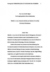
guide regions and propagation losses in the overlayer. The grating transmission showed a clear notch at 1546.7 nm with a depth of approximately 4.7 dB 共66%兲 and a bandwidth at layer 共C兲 the field enhancement at the surface provides for full width at half maximum power (⌬ FWHM) of 0.08 nm. At strong interaction of the guided field with the grating. wavelengths shorter than the Bragg wavelength the transmisWaveguides were fabricated by ion exchange in two sion spectrum shows an increased broadband loss, which is BK-7 glass substrates in molten potassium nitrate through attributed to coupling to radiation modes. The insertion loss aluminum mask openings ranging from 3 to 8 m, at 400 °C of the waveguide overlayer clearly remained low even after for 11 h.10 Polycrystalline indium oxide thin films, one of UV exposure of the film. Exposures with higher energy denthickness 100 nm and one of thickness 135 nm, were sputsities or a larger number of pulses resulted in significantly tered on two waveguide chips using dc-magnetron sputtering greater absorption loss and weaker grating strengths. Annealin a 100% O2 atmosphere to cover a 25 mm length in the ing of the waveguide chip up to 250 °C for 2 h in an oxygen center of the 40-mm-long waveguides. The overlaid atmosphere reduced the loss further by almost 1 dB. The waveguides were exposed to a high-contrast UV fringe patreflection spectrum shows that reflected power is strongly tern with period of 514.3 nm using the three-mirror interfercoupled into the backward-traveling waveguide mode at ometer described previously.6 The spatial distribution of the 1546.7 nm. However, the grating strength in reflection is laser output was homogenized during recording using a roreduced to approximately 38% due to the additional backtating fused silica plate. Gratings of 16 mm length were proground losses. No detectable grating response was observed duced on each set of waveguides by exposure to an average for the TM polarization in reflection or transmission for a pulse energy density of 45– 60 mJ/cm2 using between 5 and broadband of inspection over the amplified spontaneous 100 pulses. A scanning electron micrograph of a grating abemission spectrum of the erbium-doped fiber amplifier from lated in a 100-nm-thick InOx film using 20 pulses of energy 1520 to 1580 nm. Simulations using the beam propagation density 45 mJ/cm2 is shown in Fig. 2. method show that the phase-matching wavelength for reflecWaveguide transmission spectra were obtained before tion in the TM polarization is expected to be of order 0.4 nm InOx deposition and after grating micromachining. Broadshorter than for TE polarization. Due to the presence of the band amplified spontaneous emission from an erbium-doped high index film on the waveguide surface, the electromagfiber amplifier was coupled into each waveguide in turn usnetic boundary conditions yield much greater intensity at the ing a monomode fiber. The waveguide output was collected surface of the indium oxide film for the TE than for the TM by two x10 microscope objective lenses and an intermediate polarization.9 In the present case the grating coupling conIR polarizer and launched into a multi-mode fiber coupled to stant for the TM polarization was calculated to be 3.75 times an optical spectrum analyzer. The polarized transmission smaller than that for the TE polarization, resulting in a gratspectra for the waveguides were found by normalizing these ing of predicted reflectivity no greater than 0.4 dB. Imperspectra to that obtained with the monomode fiber butted difections in the grating reduce the peak reflectivity further rectly to the multi-mode fiber. Reflection spectra were obrendering this reflection immeasurable in comparison with tained using a fiber coupler at the input. The transmission spectral noise in the waveguide measurements. losses of the waveguides before deposition of the InOx films, Figure 4共a兲 shows the reflection spectra for waveguides including input fiber coupling losses, were less than 3 dB for with ion-exchange mask widths from 3 to 8 m, coated with both polarizations. 100 nm InOx and exposed to 20 pulses of energy density The transmission and reflection spectra for the TE polar60 mJ/cm2. Figure 4共b兲 summarizes these data by showing ization of an 8-m-wide channel waveguide overlaid with a the reflection wavelength and peak reflectivity plotted 135-nm-thick InOx film supporting a grating ablated using against ion-exchange mask width. There is a near-linear defive pulses of energy density 60 mJ/cm2 are shown in Fig. 3. pendence of the Bragg grating wavelength on the waveguide The average grating depth was estimated to be approxiwidth, exhibiting a slope of 0.12 nm/m width change over mately 20 nm by atomic force microscope measurements. this range. The grating strength in reflection increased from The transmission spectrum shows a broadband loss of about 3.0% and 14.8% for the same range of channels. The in4 dB, mainly due to fiber-waveguide coupling loss, including of gratingsee reflectivity with the waveguide width is the transition losses between the coated and uncoated waveDownloaded 15 Feb 2001 to 152.78.175.16. Redistribution subjectcrease to AIP copyright, http://ojps.aip.org/aplo/aplcpyrts.html
696
Pissadakis et al.
Appl. Phys. Lett., Vol. 78, No. 6, 5 February 2001
In conclusion, relief Bragg reflection gratings have been micromachined by 248 nm interferometric excimer laser ablation on potassium ion-exchanged channel waveguides in BK-7 glass overlaid with a thin high-index InOx film. Using five pulses of energy density 60 mJ/cm2, a narrowband spectral transmittance notch of at least 66% and ⌬ FWHM ⬍0.1 nm was obtained at 1547 nm in the TE polarization for a waveguide having a nominal width of 8 m and a 135-nmthick InOx overlayer. In waveguides coated with 100 nm InOx , with widths increasing from 3 to 8 m, the reflection wavelength shifted by 0.12 nm/m and the reflectivity increased monotonically. Low-loss, polarization insensitive devices based on high-index overlaid waveguide gratings may be used for gain flattening or for wavelength add-drop applications. Further optimization of the device is directed towards the reduction of the UV-induced losses, and control of polarization sensitivity through optimization of overlayer film thickness. 1
FIG. 4. 共a兲 Grating reflection spectra and 共b兲 peak reflectivity 共circles兲 and Bragg wavelength 共squares兲 vs waveguide width, for the TE polarization for waveguides overlaid with a 100-nm-thick InOx film exposed to 20 pulses of energy density 60 mJ/cm2.
attributed to the greater confinement of the guiding mode closer to the surface of the waveguide channel, resulting in stronger interaction with the grating corrugation. Grating strengths up to 20 dB, accompanied by higher transmission losses, have also been observed in Ta2O5 overlaid devices and further details and comparative data will be presented elsewhere.
D. C. Flanders, H. Kogelnik, R. V. Schmidt, and C. V. Shank, Appl. Phys. Lett. 24, 194 共1974兲. 2 D. F. Geragthy, D. Provenzano, W. K. Marshall, S. Honkanen, A. Yariv, and N. Peyghambarian, Electron. Lett. 35, 585 共1999兲. 3 M. Ibsen, J. Hubner, J. E. Pedersen, R. Kromann, L.-U. A. Andersen, and M. Kristensen, Electron. Lett. 32, 2233 共1996兲. 4 J. E. Roman and K. A. Winick, Appl. Phys. Lett. 61, 2744 共1992兲. 5 R. Adar, C. H. Henry, R. C. Kistler, and R. F. Kazarinov, Appl. Phys. Lett. 60, 1779 共1992兲. 6 S. Pissadakis, L. Reekie, M. Hempstead, M. N. Zervas, and J. S. Wilkinson, Appl. Surf. Sci. 153, 200 共2000兲. 7 S. Pissadakis, L. Reekie, J. S. Wilkinson, and G. Kiriakidis, Proc. Conference on Lasers and Electro-Optics, Europe, Nice, France, 2000, CWF50. 8 C. P. Hussel and R. V. Ramaswamy, IEEE Photonics Technol. Lett. 9, 636 共1997兲. 9 G. R. Quigley, R. D. Harris, and J. S. Wilkinson, Appl. Opt. 38, 6036 共1999兲. 10 T. Feuchter, E. K. Mwarania, J. Wang, L. Reekie, and J. S. Wilkinson, IEEE Photonics Technol. Lett. 4, 542 共1992兲.
Downloaded 15 Feb 2001 to 152.78.175.16. Redistribution subject to AIP copyright, see http://ojps.aip.org/aplo/aplcpyrts.html