APPLIED PHYSICS LETTERS
VOLUME 77, NUMBER 9
28 AUGUST 2000
Observation of magnetic domain structure in a ferromagnetic semiconductor „Ga, Mn…As with a scanning Hall probe microscope T. Shono and T. Hasegawa Materials and Structures Laboratory, Tokyo Institute of Technology, Nagatsuta 4259, Midori-ku, Yokohama 226-8503, Japan and CREST, Japan Science and Technology Corporation, Japan
T. Fukumuraa) Department of Innovative Engineered Materials, Tokyo Institute of Technology, Nagatsuta 4259, Midori-ku, Yokohama 226-8502, Japan
F. Matsukura and H. Ohno Laboratory for Electronic Intelligent Systems, Research Institute of Electrical Communication, Tohoku University, 2-1-1 Katahira, Aoba-ku, Sendai 980-8577, Japan
共Received 4 May 2000; accepted for publication 12 July 2000兲 We have performed low-temperature scanning Hall probe microscopy on a ferromagnetic semiconductor 共Ga0.957Mn0.043兲As. The observed magnetic domain structure is a stripe-shaped pattern as has been observed in conventional nonsemiconductor ferromagnetic materials, and the measured magnetic field from the sample surface was small, reflecting the weak magnetization of 共Ga, Mn兲As. The domain width increased and the measured magnetic field decreased with raising temperature, which are consistent with calculated results, in which the exchange interaction between Mn spins deduced from the Curie temperature is assumed. © 2000 American Institute of Physics. 关S0003-6951共00兲04935-4兴
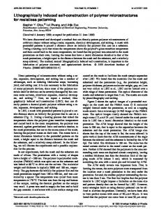
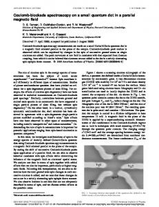
which magnetostatic energy and domain-wall energy are taken into account. A 0.2-m-thick 共Ga0.957Mn0.043兲As film was grown epitaxially on a semi-insulating GaAs共001兲 substrate at 250 °C by the use of the molecular-beam epitaxy technique. The perpendicular magnetization at zero field was realized by the introduction of tensile strain into the 共Ga, Mn兲As layer using 1-m-thick 共In0.16Ga0.84兲As buffer layer.8,9 T C is 80 K determined from a magnetization measurement. A homemade SHPM was utilized for the variable temperature measurements.10 The Hall probe with the junction of 1 m ⫻1 m was scanned h⬃0.5 m above the sample surface in order to detect the local magnetic field perpendicular to the sample surface. Figure 1 shows the observed magnetic images of the 共Ga, Mn兲As film at 9–77 K. The horizontal axes of the images are along 具 100典 . The color denotes the magnetic field perpendicular to the sample surface B Z . Note that each figure of Fig. 1 has a different scale of B Z , and that the scanning area for the upper and lower panels are 4.75⫻4.75 and 7.3⫻7.3 m2, respectively. The red and blue areas correspond to positive and negative B Z , respectively, hence, white boundaries with B Z ⬃0 correspond to the magnetic domain walls. The stripe direction is nearly parallel to the 具 110典 , reflecting the magnetocrystalline anisotropy, which is consistent with the theoretical prediction by the use of k• p perturbation method.11 The stripe-shaped domain is preserved in a wide temperature range up to T C , as can be seen from Fig. 1. The width of the domain d becomes wider, and B Z decreases with raising temperature. Figure 2 共square symbols兲 shows the temperature dependence of d. At 9 K, d is 1.5 m, then gradually increases with raising temperature for T⬍60 K, and steeply increases for T⬎60 K up to ⬃6 m around T C .
Success in growth of ferromagnetic III–V-based diluted magnetic semiconductors has opened up the possibility of semiconducting devices which combine the functionality of semiconductors with that of ferromagnetic materials.1–4 In magnetic materials, both the size and the shape of the magnetic domains are among the most fundamental quantities, because they reflect the magnitude and anisotropy of the microscopic exchange interaction. In addition, the domain structure is associated with the carrier conduction and the possible minimum size of magnetic bits in magnetic recording media, which are of technological importance for both electronic and magnetic devices. However, there have been no experiments in order to observe the magnetic domain structures of III–V ferromagnetic semiconductors. Recently, several scanning probe microscopic techniques for studying local magnetic properties, which detect the magnetic field from the sample surface, have been developed, such as the magnetic-force microscope,5 the scanning superconducting quantum interference device microscope,6 and the scanning Hall probe microscope 共SHPM兲.7 The SHPM has advantages of less magnetic invasiveness for the specimen and a wider operating temperature range, the latter being suitable for studying the temperature variation of the domain structure. Here, we report SHPM measurements of the magnetic domain structure in a ferromagnetic semiconductor 共Ga, Mn兲As film. The results clearly showed stripe-shaped domains with their widths depending on temperature below the Curie temperature T C . The domain width and the magnitude of the magnetic field from the domain structures are discussed on the basis of a classical magnetic domain model in a兲
Electronic mail:
[email protected]
0003-6951/2000/77(9)/1363/3/$17.00
1363
© 2000 American Institute of Physics
1364
Appl. Phys. Lett., Vol. 77, No. 9, 28 August 2000
Shono et al.
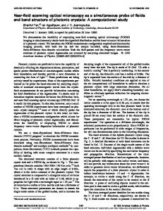
FIG. 3. Temperature dependence of the measured and calculated maximum max 共circle symbol兲, respecmagnetic field, B Zmax 共square symbol兲 and B Z,cal tively. The inset shows configurations of the magnetic domains and Hall sensor. d is the domain width, L the domain thickness, and h the sample– probe distance. Arrows denote magnetization. Full lines are guides for the eyes.
FIG. 1. 共Color兲 Magnetic images of 共Ga, Mn兲As obtained by scanning Hall probe microscope. Measurement temperatures are 共a兲 9 K, 共b兲 20 K, 共c兲 30 K, 共d兲 65 K, 共e兲 70 K, and 共f兲 77 K. The image areas are 4.8⫻4.8 m2 for 9–30 K and 7.3⫻7.3 m2 for 63–77 K. The horizontal axes are 具 100典 . The red and blue regions denote positive and negative B Z , respectively.
Figure 3 共square symbols兲 shows the temperature dependence of the maximum value of B Z above the center of the domain, B Zmax . At 9 K, B Zmax is ⬃4 mT, and decreases almost linearly with temperature up to about 60 K, then decreases slowly above 60 K. In order to calculate the magnitude of B Zmax , a stripe-shaped domain model is employed as described below. The magnetic field perpendicular to the surface above a perpendicularly magnetized thin film with stripe domain array as functions of d, the thickness of the domain L, and a location (x,h), as illustrated in the inset of Fig. 3, is given by Eq. 共6兲 in Ref. 12. In our case, the size of the Hall junction is nonzero so that the measured magnetic field should be averaged over the area of the Hall junction excluding the depletion layer, about 0.8⫻0.8 m2. Figure 3 共circle max , by using d at symbols兲 shows the calculated B Zmax , B Z,cal each temperature, h⫽0.5 m, L⫽0.2 m, and the spontaneous magnetization M S obtained from an Arrott plot as a function of temperature.13 M S decreases largely with increasing temperature near T C according to the temperature dependence of a Brillouin function. However, the decrease in max B Z,cal , depending on both M S and d, is not large but approximately linear in temperature, since d increases largely max is in quantitative with increasing temperature near T C . B Z,cal
FIG. 2. Temperature dependence of the observed and the calculated domain widths, d 共square symbol兲 and d cal 共circle symbol兲, respectively. Full lines are guides for the eyes.
agreement with B Zmax 共square symbols兲, therefore, there is no magnetic domain smaller than the spatial resolution of the present SHPM. If a smaller domain exists, magnetic fields from the adjacent domains cancel out each other, resulting in considerable reduction of B Zmax . The agreement between max also confirms that the domain structure in this B Zmax and B Z,cal compound is composed of a single magnetic domain in the direction perpendicular to the surface since L is assumed to be the whole film thickness in the present calculation. It is well known that the most stable domain structure in ferromagnetic materials with perpendicular magnetization under no external magnetic field is the stripe domain array.14 d is determined so as to minimize the sum of the magnetostatic energy and domain-wall energy, and expected to be expressed as d⫽3.04⫻10⫺3 ( ␥ L) 1/2/M S in Kennely’s SI unit.15 ␥ is the domain-wall energy per unit area given by ␥ ⫽4 (nJS 2 xK/a) 1/2, where n is the number of cation sites in the unit cell, J the exchange between Mn spins, S the magnitude of the Mn spin, x the molar concentration of Mn, K the magnetocrystalline anisotropic constant, and a the lattice constant. We assumed J between Mn spins substituted for Ga sites taking the nearest-neighbor cations into consideration in mean-field theory as J⫽3k B T C /2zS(S⫹1)x, where k B is the Boltzmann constant, and z is the number of nearest-neighbor cation sites.13,16 Using the relation between the magnetic anisotropic energy E a and K, E a ⬇K sin2 , K ⫽1.0⫻104 J/m3 is obtained from the hysteresis loss in the magnetic-field dependence of the Hall resistivity at various angles between the magnetic field and the easymagnetization axis at 10 K.9 Taking T C ⫽80 K, n⫽4, z ⫽12, S⫽5/2, and a⫽0.567 nm, ␥ is calculated to be 3.4 ⫻10⫺4 J/m2. The calculated temperature dependence of domain width d cal by the use of the obtained ␥ and M S determined from the Arrott plot as a function of temperature and L⫽0.2 m of the thickness of the 共Ga, Mn兲As layer, well reproduces d, as shown in Fig. 2 共circle symbols兲. d cal is weakly temperature dependent below 60 K and abruptly increases near T C mainly due to the reduction of M S , where the disagreement between d and d cal due to the neglect of the temperature dependence of K is observed. In summary, we have observed the magnetic domain structure of 共Ga, Mn兲As by using a scanning Hall probe microscope. It is shown that 共Ga, Mn兲As has stripe-shaped do-
Shono et al.
Appl. Phys. Lett., Vol. 77, No. 9, 28 August 2000
mains with widths of 1.5–6.4 m increasing with raising temperature for 9–77 K. The measured magnetic field can be quantitatively accounted for in the perpendicularly magnetized thin-film model. Hence the domain width is not smaller than 1 m parallel to the sample surface and the structure is composed of a single domain perpendicular to the surface. The observed domain widths are reproduced by a model considering the magnetostatic and domain-wall energies, assuming exchange interaction deduced from T C . The work at Tohoku University was partially supported by the Japan Society for the Promotion of Science 共JSPSRFTF97P00202兲 and by the Ministry of Education, Japan 共Nos. 9244103 and 12305001兲. 1
H. Munekata, H. Ohno, S. von Molna´r, A. Segmu¨ller, L. L. Chang, and L. Esaki, Phys. Rev. Lett. 63, 1849 共1989兲. 2 H. Ohno, H. Munekata, T. Penny, S. von Molna´r, A. Segmu¨ller, and L. L. Chang, Phys. Rev. Lett. 68, 2664 共1992兲. 3 H. Ohno, A. Shen, F. Matsukura, A. Oiwa, A. Endo, S. Katsumoto, and Y. Iye, Appl. Phys. Lett. 69, 363 共1996兲. 4 H. Ohno, J. Magn. Magn. Mater. 200, 110 共1999兲.
5
1365
Y. Martin, D. Rugar, and H. K. Wickramasinghe, Appl. Phys. Lett. 52, 244 共1988兲. 6 L. N. Vu, M. S. Wistrom, and D. J. Van Harlingen, Appl. Phys. Lett. 63, 1693 共1993兲. 7 A. M. Chang, H. D. Hallen, L. Harriot, H. F. Hess, H. L. Loa, J. Kao, R. E. Miller, and T. Y. Chang, Appl. Phys. Lett. 61, 1974 共1992兲. 8 H. Ohno, F. Matsukura, A. Shen, Y. Sugawara, A. Oiwa, A. Endo, S. Katsumoto, and Y. Iye, in Proceeding of the 23rd International Conference on the Physics of Semiconductors, Berlin, edited by M. Scheffler and R. Zimmermann 共World Scientific, Singapore, 1996兲, p. 405. 9 A. Shen, H. Ohno, F. Matsukura, Y. Sugawara, N. Akiba, T. Kuroiwa, A. Oiwa, A. Endo, S. Katsumoto, and Y. Iye, J. Cryst. Growth 175Õ176, 1069 共1997兲. 10 T. Fukumura, H. Sugawara, T. Hasegawa, K. Kitazawa, Y. Nagamune, T. Noda, and H. Sakaki, Micron 30, 575 共1999兲. 11 T. Dietl, H. Ohno, F. Matsukura, J. Cibert, and D. Ferrand, Science 287, 1019 共2000兲. 12 H. J. Hug, B. Stiefel, A. Moser, I. Parashikov, A. Klicznik, D. Lipp, H.-J. Guntherrodt, G. Bochi, D. I. Paul, and R. C. Handley, J. Appl. Phys. 79, 5609 共1996兲. 13 F. Matsukura, H. Ohno, A. Shen, and Y. Sugawara, Phys. Rev. B 57, R2037 共1998兲. 14 A. Hubert and R. Scha¨fer, Magnetic Domains 共Springer, New York, 1998兲. 15 C. Kittel, Rev. Mod. Phys. 21, 541 共1949兲. 16 C. Kittel, Introduction to Solid State Physics 共Wiley, New York, 1966兲.