APPLIED PHYSICS LETTERS
VOLUME 75, NUMBER 5
2 AUGUST 1999
High-speed, optically controlled surface-normal optical switch based on diffusive conduction M. B. Yairi,a) C. W. Coldren, D. A. B. Miller, and J. S. Harris, Jr. Stanford University, Stanford, California 94305
共Received 21 December 1998; accepted for publication 7 June 1999兲 We report a surface-normal optically controlled optoelectronic modulator made from a reversed biased p-i 共multiple quantum well兲-n GaAs/AlGaAs structure with ultrathin barriers 共5 Å兲 whose recovery time is based on diffusive conduction. Modulation of reflectivity from 0.3 to 0.6 and back again in about 50 ps was demonstrated using a 750 fJ control pulse at 855 nm. We also demonstrated modulated changes in power greater than the control pulse power—a type of signal gain—by a factor of 1.8-to-1. Strong changes in reflectivity combined with low required control power make this device potentially useful for high-speed switching arrays in such applications as time division demultiplexing. © 1999 American Institute of Physics. 关S0003-6951共99兲00331-9兴
ing states 共the ‘‘ON’’ state of the device兲 will last only while the bias voltage remains screened. The decay mechanism of this screening is due to diffusive conduction.11 Since this decay mechanism does not require the initial photogenerated charge to be removed, speed is not limited by external RC time constants or carrier lifetimes. If the spot size of the control pulse is small with respect to the surface area of the device, then as the photocarriers vertically separate, they will build up a localized screening voltage which views the device as a two-dimensional 共2D兲 dissipative wire: there is a capacitance per unit area across the intrinsic region 共vertically兲, while there is a resistance per square across the p and n regions 共horizontally兲. As such, the voltage obeys a diffusion equation given by
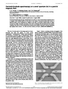
High-speed switches have a wide variety of potential applications in optical and optoelectronic systems and communications. Optically controlled, fiber-based switches such as loop mirrors or soliton gates can be very fast with good contrast ratios, low power, and cascadable Boolean logic, but they are difficult to arrange in arrays and integrate with electronics 关e.g., complementary metal–oxide–semiconductors 共CMOS兲兴.1–4 Waveguide switches offer reasonably good contrast and speed, but they are limited to one-dimensional arrays.5,6 Surface-normal semiconductor quantum well switches, on the other hand, can be integrated with CMOS circuitry.7 Surface-normal quantum well 共QW兲 devices have already been investigated extensively for switching at lower speeds and bistable switching has been demonstrated with times as short as 33 ps.8,9 In contrast to these previous devices, the device described in this work operates entirely with pulsed light. As we will show, this new device can be used as the basis for a novel kind of high-speed optically controlled switch. This type of switch may be useful for applications such as time division demultiplexing where an interface is needed between the extremely fast bit rates possible in optical fiber and the relatively slow speed of CMOS processing. The device we have built is a reverse-biased p-i共multiple QW兲-n GaAs/AlGaAs structure whose reflectivity may be changed by a control pulse of light, as Fig. 1 illustrates. The device may be made initially 共relatively兲 opaque by appropriate biasing. If a control pulse hits the device, its light is absorbed in the QWs. Due to the bias-induced electric field, the photogenerated electrons and holes escape from the QWs and are pulled toward the n and p regions, respectively. As they move, these same charges screen the reverse bias, blueshifting the exciton absorption peak due to the quantum confined Stark effect 共QCSE兲.10 While this screening lasts, the effective absorption of the device is reduced, allowing a second, signal pulse to be strongly transmitted 共or in the presence of a buried mirror, strongly reflected兲. As mentioned above, the duration of the strongly reflect-
dV ⫽Dⵜ 2xy V, dt
where the diffusion coefficient is simply D⫽1/R SQC A ; here R SQ is the sum of the resistances per square of the p and n regions and C A is the capacitance per area across the intrin-
FIG. 1. Schematic device behavior over time with incident pump 共1st, control兲 and probe 共2nd, signal兲 pulses. Control pulse is absorbed in reversebiased device, creating electrons and holes that move to shield the voltage locally and consequently reduce the absorption of the device such that the signal pulse may be strongly reflected. As the shielding voltage dissipates, the device returns to its opaque state.
a兲
Electronic mail:
[email protected]
0003-6951/99/75(5)/597/3/$15.00
共1兲
597
© 1999 American Institute of Physics
598
Yairi et al.
Appl. Phys. Lett., Vol. 75, No. 5, 2 August 1999
sic region. If we assume a Gaussian distribution of carriers due to the pulse intensity shape, the voltage dynamics from a spatial Gaussian screening ‘‘impulse’’ at time t⫽0 can be described in a straightforward manner as V 共 r,t 兲 ⫽V M
c t⫹ c
冉
exp ⫺
r2 4D 共 t⫹ c 兲
冊
,
共2兲
in which c is the effective decay time constant equal to w 2 /8D, where w is the spot size radius of the pump pulse. It is worth noting that c is strongly dependent on controllable parameters 共spot size and doping levels兲 and typical values can give time constants on the order of picoseconds. Because it is the voltage and not the carriers themselves which dissipates and spreads, this effect is not limited by carrier diffusion, and because the device can effectively recover through local diffusive conduction the recovery time is not dominated by the external circuitry 共and its relatively long RC time constants兲. In addition to the ‘‘local’’ optical modulation recovery rate, there is also a ‘‘global’’ device repetition rate determined simply by the 共arbitrary兲 pulse repetition period. Though the fixed pulse generation rate 共⬃80 MHz兲 of the laser used precluded experimental testing, we believe that as the repetition rates increases, a steady-state unrelaxed charge begins to build up, shifting the effective bias point of the device. This shift—roughly proportional to the ratio of the RC value of the device to the time period between pulses— may be easily compensated by adjusting the bias voltage and does not of itself limit the repetition rate. Other mechanisms, such as limits on power dissipation, might set the practical limit on repetition rate. The ‘‘turn-on’’ time of the device depends on the escape and subsequent transport of the photogenerated electrons and holes. Using ultrathin barriers between the quantum wells we hoped to both improve modulation speed via tunneling or assisted tunneling as well as to increase contrast with a larger number of QWs for a given length of the intrinsic region. Despite the very thin barriers, the device shows strong QCSE shifts that dominate the electroabsorption in our experiments 共various interwell coupling effects can also be seen兲. Other recent studies of carrier transport across quantum wells have focused on the dynamics of shallow QWs 共which allow rapid thermal escape兲.12 The device was grown by solid source molecular beam epitaxy 共MBE兲 on an n ⫹ GaAs共001兲 wafer. The structure consisted of 20 pairs of n-doped Si 9⫻1017 cm⫺3) AlAs/Al0.10Ga0.90As quarter wave layers forming a distributed Bragg reflector 共DBR兲 with a center wavelength of 850 nm, followed by an intrinsic region consisting of 94⫻100 Å QWs separated by 5 Å AlAs barriers, and finally a 1.1 m Al0.10Ga0.90As p region 共Be 3⫻1018 cm⫺3) capped by 50 Å of heavily p-doped GaAs 共Be 1⫻1019 cm⫺3). Standard photolithography and wet chemical etching were used to make 300 m mesas. A Si3N4 antireflection coating was deposited on top of the mesas and metal ring contacts were made to the p and n regions followed by wire bonding. In our setup, a diode-pumped Nd:YVO4 共Millenia兲 laser pumped a Tsunami Ti-sapphire laser producing 2 ps pulses at 82 MHz. Each pulse is split in a pump-probe setup such that only the re-
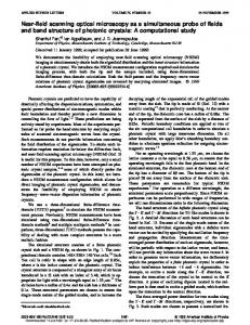
FIG. 2. Reflectivity modulation of probe 共signal兲 pulse as a function of time with ⫺6.3 V bias across device and 855 nm light at various pump 共control兲 pulse powers with a spot size of 50 m2. Simulation 共solid lines兲— reflectivity modulation at various input powers. The good fit of the tails to a hyperbolic decay is a good indication that diffusive conduction is responsible for the voltage dissipation.
flected 共chopped兲 probe light 共the second pulse兲 is captured by a photodetector and sent to a lock-in amplifier. The results are shown in Fig. 2. Using a 750 fJ pump pulse with a spot size of 7 m radius 共⬃5 fJ m2兲 tuned to 855 nm and the device biased at ⫺6.3 V, the heavy hole exciton is strongly absorbing. As can be easily seen in the figure, the probe pulse experiences a reflectivity change with a contrast ratio of 1.8-to-1 and an absolute change in reflectivity of 0.3. The high-reflectivity state of the device induced by the pump pulse decays within about 50 ps. The device exhibits this type of behavior when the laser is tuned between 855 and 865 nm, with the contrast ratio falling to about 30% at the high-wavelength end. The energy needed for switching is very low—less than a picojoule—and compares very favorably with the other switching mechanisms mentioned at the beginning of this report. This low required energy is possible because once the carriers from a single well reach the n and p regions, the resulting screening affects all of the QWs. Hence, the carriers created from all of the 94 QWs ultimately move to create a much larger electric field change across any single QW than would be possible with carriers from that QW alone. Low switching energy arises naturally from this when combined with the strongly fielddependent absorption of the QWs. Figure 2 also compares medium 共750 fJ兲 and large-signal 共1500 fJ兲 data to simulation. The model includes the following parameters: a Gaussian distribution for the creation of electrons and holes based on the spot size of the pulse; effective escape times from the wells for both electrons and holes; vertical field-dependent velocity—also for both carrier types; and a diffusion coefficient. The model tracks each electron and hole and, using Eq. 共2兲 and Poisson’s equation, calculates the position-dependent field across the device. This is incorporated into a time sequential process that, when combined with empirical voltage-dependent reflectivity data, determines the reflectivity as a function of time. This discrete time process is comparable to the continuous time, Green’s function approach taken by Yang.12 The calculated diffusion coefficient is 2⫻105 cm2/s as-
Yairi et al.
Appl. Phys. Lett., Vol. 75, No. 5, 2 August 1999
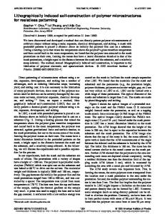
suming C A ⫽0.1 fJ/cm2. There is some uncertainty in the resistance and capacitance values, however, so instead we used 0.4⫻105 cm2/s based on measured values from similar structures by Yang.12 Maximum drift velocity was set to 1.0 and 0.6⫻107 cm/s for electrons and holes, respectively. Escape times are difficult to determine. As an approximation, we used a tunneling resonance simulation to determine energy resonance widths and hence lifetimes. With a 6.3 ⫻104 V/cm field across our structure, the simulated electron and hole tunneling times were roughly 3 and 20 ps, respectively. Tunneling time is field dependent, however, particularly for the electrons. Rapid field screening at larger optical powers may also increase the average expected escape time for carriers still trapped. For the three curves shown, reasonable fits were found with electron escape set at 5, 7, and 10 ps with increasing pump power 共this was the only parameter varied between the different simulations兲. The close fit between data, particularly for the tails, gives strong support for our hypothesis that it is indeed diffusive conduction that is the mechanism primarily responsible for voltage decay. The device recovery time is long, especially when compared to the expected rapid voltage diffusion time coefficient that is on the order of a picosecond. We believe this may be due to a long hole escape time from the quantum wells. Reducing the hole escape time should make this type of device much faster and is the focus of future work. Moreover, the presence of these holes changes the spatial electric field screening across the QWs which, when combined with the nonlinear field dependence of the absorption, limits change in reflectivity. The device can also be improved 共reduced ‘‘turn-on’’ time 兲 by making use of faster changes in absorption as a function of electric field, such as possibly Wannier– Stark localization. The percentage change in probe reflectivity—induced by the pump pulse—should be nominally independent of probe power. Normally the pump pulse induces changes in reflected probe power which are small compared to the pump power. However, if the incoming probe power is made large compared to the pump, the changes in reflected probe power can be larger than the pump power itself—in effect creating gain in the reflected signal. Figure 3 demonstrates this effect 共though there was some reduction in the percentage change in reflectivity at such high probe powers兲, showing gain close to a factor of 2. In summary, we have demonstrated an optically controlled surface-normal switch which can be switched in 50 ps with reflectivity swings from 0.3 to 0.6. This type of device should be integrable with CMOS 共via flip-chip bonding兲, acting concurrently as a photodetector at CMOS speeds by mea-
599
FIG. 3. Change in reflected probe 共signal兲 power normalized against pump 共control兲 pulse power—equivalent to signal gain with the device biased at ⫺6.0 V, pump power of 750 fJ, and probe power of 2.56 pJ at 855 nm.
suring the photoinduced current as well as allowing control of the switch operation through the bias voltage. The quantum confined Stark effect and diffusive conduction seem to be the mechanisms primarily responsible for the large change in reflectivity and fast recovery time, respectively. Signal gain using the same device has also been shown. One of the authors 共M.B.Y.兲 was supported by an ARO NDSEG fellowship; this work was also supported by ARO Grant No. DAA55-98-1-0160.
1
J. P. Sokoloff, P. R. Prucnal, I. Glesk, and M. Kane, IEEE Photonics Technol. Lett. 5, 787 共1993兲. 2 M. N. Islam, C. E. Soccolich, and J. P. Gordon, Opt. Quantum Electron. 24, S1215 共1992兲. 3 R. J. Manning, A. D. Ellis, A. J. Poustie, and K. J. Blow, J. Opt. Soc. Am. B 14, 3204 共1997兲. 4 K. H. Ahn, X. D. Cao, Y. Liang, B. C. Barnett, S. Chaikamnerd, and M. N. Islam, J. Opt. Soc. Am. B 14, 1228 共1997兲. 5 P. LiKamWa and A. M. Kan’an, IEEE J. Quantum Electron. 2, 655 共1996兲. 6 A. M. Kan’an and P. LiKamWa, J. Opt. Soc. Am. B 14, 3217 共1997兲. 7 K. W. Goossen, J. A. Walker, L. A. D’Asaro, S. P. Hui, B. Tseng, R. Leibenguth, D. Kossives, D. D. Bacon, D. Dahringer, L. M. F. Chirovsky, A. L. Lentine, and D. A. B. Miller, IEEE Photonics Technol. Lett. 7, 360 共1995兲. 8 A. L. Lentine and D. A. B. Miller, IEEE J. Quantum Electron. 29, 655 共1993兲. 9 G. D. Boyd, A. M. Fox, D. A. B. Miller, L. M. F. Chirovsky, L. A. D’Asaro, J. M. Kuo, R. F. Kopf, and A. L. Lentine, Appl. Phys. Lett. 57, 1843 共1990兲. 10 D. A. B. Miller, D. S. Chemla, T. C. Damen, A. C. Gossard, W. Wiegmann, T. H. Wood, and C. A. Burrus, Phys. Rev. B 32, 1043 共1985兲. 11 G. Livescu, D. A. B. Miller, T. Sizer, D. J. Burrows, J. Cunningham, A. C. Gossard, and J. H. English, Appl. Phys. Lett. 54, 748 共1989兲. 12 C. M. Yang, E. Canoglu, E. Garmire, K. W. Goossen, J. E. Cunningham, and W. Y. Jan, IEEE J. Quantum Electron. 33, 1498 共1997兲.