University of Warwick institutional repository: http://go.warwick.ac.uk/wrap This paper is made available online in accordance with publisher policies. Please scroll down to view the document itself. Please refer to the repository record for this item and our policy information available from the repository home page for further information. To see the final version of this paper please visit the publisher’s website. Access to the published version may require a subscription. Author(s): M. A. Sadeghzadeh, A. I. Horrell, O. A. Mironov, E. H. C. Parker, T. E. Whall, and M. J. Kearney Article Title: Wave function-dependent mobility and suppression of interface roughness scattering in a strained SiGe p-channel field-effect structure Year of publication: 2000 Link to published version: http://dx.doi.org/10.1063/1.126410 Publisher statement: None
APPLIED PHYSICS LETTERS
VOLUME 76, NUMBER 18
1 MAY 2000
Wave function-dependent mobility and suppression of interface roughness scattering in a strained SiGe p-channel field-effect structure M. A. Sadeghzadeh, A. I. Horrell,a) O. A. Mironov,b) E. H. C. Parker, T. E. Whall,c) and M. J. Kearneya) Department of Physics, The University of Warwick Coventry, CV4 7AL, United Kingdom
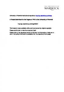
共Received 9 November 1999; accepted for publication 7 March 2000兲 The 4 K Hall mobility has been measured in a top-gated, inverted, modulation-doped Si/Si0.8Ge0.2 structure having a Si:B doping layer beneath the alloy. From comparisons with theoretical calculations, we argue that, unlike an ordinary enhancement-mode SiGe p-channel metal–oxide– semiconductor structure, this configuration leads to a decrease of interface roughness scattering with increasing sheet carrier density. We also speculate on the nature of the interface charge observed in these structures at low temperature. © 2000 American Institute of Physics. 关S0003-6951共00兲01518-7兴 Sakaki1 first pointed out that deformation of the wave function by gating could be used to realize a velocity modulation transistor and Kurobe2 calculated the effects of such a wave form deformation on the transport times in a back gated GaAs/AlGaAs heterostructure. Wave function manipulation also has relevance for the worldwide efforts to fabricate SiGe p-channel metal–oxide–semiconductor (pMOS) devices of enhanced carrier mobilities as compared to Si pMOS. A particularly attractive structure for SiGe pMOS, first investigated by Verdonckt-Vandebroek et al.,3 is one having a n⫹ poly-Si gate with a boron layer beneath the alloy. This combination minimizes parallel conduction in the silicon cap, whilst maintaining a low threshold gate voltage. A further virtue of having the p-type doping below the alloy, as noted by Niu et al.,4 is the reduction of the 共vertical兲 effective field in the inversion layer with increasing sheet carrier density. In principle, this would correspond to an increase in the width of the wave function, rather than a decrease found in a conventional SiGe pMOS device. This would tend to reduce the deleterious effects of interface roughness scattering. Throughout this letter, the interface of concern is the back interface, i.e., the one furthest away from the gate 共see Fig. 1兲. To investigate this idea further we have fabricated the top-gated inverted modulation doped structure shown schematically in Fig. 1. The structure, intended for low temperature measurements only, was grown by solid-source molecular beam epitaxy5 on a low-doped (n-type兲 Si共100兲 substrate. The growth sequence consisted of a 200-nm-thick Si buffer layer, followed by a 30 nm Si:B doped layer (2 ⫻1018 cm⫺3 ), a 20 nm Si spacer, a 20 nm coherently strained Si0.8Ge0.2 layer, and finally a 180 nm Si capping layer. The top gate consisted of a sputtered Ti/Al Schottky barrier, and ohmic contacts for Hall measurements were made to the two-dimensional hole gas 共2DHG兲 by sputtering Al and annealing in a nitrogen ambient at 450 °C for 30 min. The absence of an oxide layer limits the maximum 共negative兲
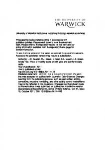
gate bias, V g , to about ⫺1.2 V 共insisting that the gate leakage current never exceeds 20 pA, as compared to the Hall measuring current of 20 nA兲. However, this still enabled us to increase the 2DHG sheet carrier density, n s , from ⬃1.5 ⫻1011 to ⬃5.2⫻1011 cm⫺2 , while the corresponding Hall mobility 共at 4 K兲 increased from ⬃700 to ⬃4650 cm2 V⫺1 s⫺1 . Single subband occupancy and transport solely at the lower heterointerface were confirmed by comparison of the carrier densities obtained from Hall and Shubnikov de-Haas measurements. As Fig. 2 shows, the measured variation of n s with V g and the corresponding Poisson– Schro¨dinger prediction 共see e.g., Ref. 6兲 are in good agreement. To calculate the mobility as a function of n s we have used the self-consistent multiple-scattering theory proposed by Gold and Go¨tze.7,8 The central equation used to evaluate the transport time, , is 1 1 ⫽ 4 n sm *
冕
⬁
0
q 3 U 2q ⬙ 共 q,i0 ⫹ 兲 dq,
共1兲
a兲
Also at: Department of Electronic and Electrical Engineering, Loughborough University, Loughborough, Leics., LE11 3TU, UK. b兲 On leave from IRE NAS of Ukraine, Kharkov 310085, Ukraine. c兲 Electronic mail:
[email protected]
FIG. 1. Schematic of the top-gated inverted modulation-doped structure and the associated valence band diagram. The B-doping slab concentration is 2⫻1018 cm⫺3 .
0003-6951/2000/76(18)/2568/3/$17.00 2568 © 2000 American Institute of Physics Downloaded 06 Jul 2009 to 137.205.202.8. Redistribution subject to AIP license or copyright; see http://apl.aip.org/apl/copyright.jsp
Sadeghzadeh et al.
Appl. Phys. Lett., Vol. 76, No. 18, 1 May 2000
FIG. 2. Measured 共circles兲 and calculated 共solid line兲 variation of carrier sheet density with gate voltage. A valence band offset of 180 meV for Si0.8Ge0.2 is assumed.
where ⬙ (q,i0 ⫹ ) is the zero-frequency density propagator 共with screening included兲 and U 2q is a scattering function or sum of such functions for each type of mechanism included. In the present work we have taken account of: 共i兲 interface roughness scattering associated with random variations in the confining potential,9 共ii兲 scattering due to strain fluctuations in the channel caused indirectly by the roughness,10 共iii兲 scattering from interface impurity charges,11 and 共iv兲 alloy disorder scattering.12 The standard model of interface roughness scattering gives U 2q ⬇
e4
⑀ L2
冉
N c⫹
ns 2
冊
2
⌬ 2q ,
共2兲
where ⌬ 2q characterizes the roughness distribution. In the present structure, N c is the capside charge density consisting of surface charges and charges induced by the gate bias. Both N c and n s are functions of V g and are determined by the Poisson–Schro¨dinger modeling exercise referred to earlier. Rather than make the standard assumption of Gaussian correlated roughness9 we will, following Ref. 10, assume a power-law distribution of roughness for which ⌬ 2q ⫽
冉
⌬ 2L 2 . q 2 L 2 n⫹1 1⫹ 4n
冊
共3兲
Here, ⌬ is a measure of the roughness amplitude deviations, L is the roughness correlation length, and the exponent n describes the falloff of the distribution at high wave numbers. For scattering from strain fluctuations due to roughness at the interface we have 共adapting the theory in Ref. 10 to a triangular confining potential兲 U 2q ⬇
f 2 ⌶ 2u 共 1⫹ 兲 2 q2 ⌬ 2, 2 4 共 1⫺ 兲 关 1⫹ 共 q/b 兲兴 6 q
共4兲
where ⌶ u 共⬃4.5 eV兲 is the deformation potential, f (⬃7.9 ⫻10⫺3 ) is the lattice mismatch factor, and 共⬃0.28兲 is Poisson’s ratio. The parameter b is the one that appears in the Fang–Howard variational wave function9
2569
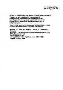
FIG. 3. Measured 4 K Hall mobility 共circles兲 vs hole sheet density compared with theory 共solid lines兲. The roughness parameters are as follows: ⌬⬃0.95 nm, L⬃1.9 nm, n⬃1. The comparison yields an interface charge density of ⬃0.9⫻1011 cm⫺2 . The relatively poor fit at high carrier densities is attributed to the breakdown of the triangular well approximation, as the width of the state approaches the alloy thickness.
b⫽
冋
冉
12m z e 2 11 N c⫹ n s ប 2⑀ L 32
冊册
1/3
,
共5兲
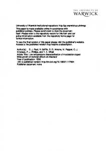
where m z 共⬃0.28 m 0 ) is the effective mass in the growth direction. Our treatment of the other two scattering mechanisms is as described in Refs. 11 and 12; the alloy disorder potential is assumed to be U AL ⬃0.6 eV. Experimental results for the 4 K Hall mobility are compared with the theoretical predictions in Fig. 3. We have taken the Hall factor to be unity 共a good approximation兲. The theory suggests, in common with previous findings,6,13,14 that interface charge plays an important role in limiting the mobility at low temperatures. Alloy disorder, interface roughness, and strain fluctuations are relatively less important at 4 K 共at least for the carrier concentration range in question兲, but at 300 K they become much more significant. One can do little about alloy disorder scattering, but the predicted trend whereby the mobility due to interface roughness and strain variations increases with n s is highly desirable for SiGe pMOS applications at 300 K.11,13,15 This trend is a direct consequence of the fact that scattering processes associated with roughness at the interface are especially sensitive to the width of the state 共wave function兲.11,16 As shown in Fig. 4, increasing n s in the present configuration corresponds to an increasing state width 共chosen to be ⬃6/b for illustrative purposes兲. In Fig. 5 we compare the calculated interface roughness and strain fluctuation limited mobilities at 4 K for the present device configuration with an ordinary enhancement mode SiGe pMOS structure,13 i.e., one not possessing the Si:B doping slab beneath the alloy, but otherwise having the same roughness parameters. Figure 5 does not represent a full calculation for realistic device structures intended for room temperature operation 共with oxide layers etc.兲, but the results do suggest that the trend towards the reduced importance of the rough interface at the higher carrier concentrations is at least plausible. The values of ⌬ 共⬃0.95 nm兲, L 共⬃1.9 nm兲, and n 共⬃1兲 chosen to fit to the mobility suggest that the interface is quite rough, although they have not been independently verified by
Downloaded 06 Jul 2009 to 137.205.202.8. Redistribution subject to AIP license or copyright; see http://apl.aip.org/apl/copyright.jsp
2570
Sadeghzadeh et al.
Appl. Phys. Lett., Vol. 76, No. 18, 1 May 2000
FIG. 4. Variation of the state 共wave function兲 width 共taken as ⬃6/b, where b is the Fang–Howard parameter兲 as a function of sheet carrier density.
structural measurements. The results are relatively insensitive to choice of n between about 1 and 3, so this is not seen as a crucial parameter. Regarding the values of ⌬ and L, there are a number of similar findings in the literature. The high-resolution electron microscopy measurements of Hull et al.17 indicate that the Si on SiGe and SiGe on Si interfaces are rough on this sort of scale. Powell et al.18 also find that the SiGe on Si and Si on SiGe surfaces have comparable roughness on a scale of order 1 nm. Finally, the results of Penner et al.19 suggest a value of the product ⌬L ⬃0.6 nm2 共cf. ⌬L⬃1.8 nm2 in the present work兲. One would hope, of course, that these values represent almost a worst case scenario, and that in time higher quality interfaces will be fabricated. Although interface charge is less relevant at 300 K, it is interesting that the value deduced for the interface charge density (n i ⬃0.9⫻1011 cm⫺2 ) corresponds closely to what has been observed previously for the upper interface.6,13 This symmetry suggests that the interface charge might be an in-
FIG. 5. Theoretical calculations of interface roughness scattering and scattering from strain fluctuations at 4 K: Solid lines-inverted structure 共present work兲, dashed lines-conventional enhancement-mode SiGe pMOS structure which does not have a Si:B doping slab below the alloy. The roughness parameters are ⌬⬃0.95 nm, L⬃1.9 nm, and n⬃1 in both cases.
trinsic effect not associated with unintentional doping of the alloy. One possibility is that it may be piezoelectric in origin. Several authors have found experimental evidence for piezoelectric effects in the Si/SiGe system.20–23 Xie et al.20,21 deduced a piezoelectric constant of 1.35⫻10⫺2 cm⫺2 for Si0.8Ge0.2 . Braithwaite et al.24 deduced a value of 0.9 ⫻10⫺2 cm⫺2 from the ab initio calculations of de Gironcoli and Molinari.25 From these results one can postulate an interface charge density of order 1011 cm⫺2 . The agreement with experiment could be fortuitous but suggests that possible piezoelectric phenomena in this strained layer system are worthy of further investigation. In conclusion, it appears that interface roughness scattering in the Si/SiGe system can be alleviated to some extent by reducing the vertical electric field in the conducting channel—equivalent to increasing the width of the hole wave function. We further speculate that the principal scattering process at the interface at 4 K might be piezoelectric in origin. Although these studies were conducted at 4 K we consider that they have important consequences for 300 K device operation. The authors wish to thank C. J. Emeleus for useful discussions, C. P. Parry and P. J. Phillips for samples growth. H. Sakaki, IEEE J. Quantum Electron. 22, 1845 共1986兲. A. Kurobe, Semicond. Sci. Technol. 8, 742 共1993兲. 3 S. Verdonckt-Vandebroek, E. F. Crabbe, B. S. Meyerson, D. L. Harame, P. J. Restle, J. M. C. Stork, A. C. Megdanis, C. L. Stanis, A. A. Bright, G. M. W. Kroesen, and A. C. Warren, IEEE Electron Device Lett. 12, 447 共1991兲. 4 G. F. Niu, G. Ruan, T. Tang, and R. Kwor, in Proceedings of the 24th European Solid-State Device Research Conference (ESDRC 94), Edinburgh, edited by C. Hill and P. Ashburn 共Editions Frontieres, 1994兲, p. 151 5 M. A. Sadeghzadeh, C. P. Parry, P. J. Phillips, E. C. H. Parker, and T. E. Whall, Appl. Phys. Lett. 74, 579 共1999兲. 6 C. J. Emeleus, T. E. Whall, D. W. Smith, R. A. Kubiak, E. H. C. Parker, and M. J. Kearney, J. Appl. Phys. 73, 3852 共1993兲. 7 A. Gold and W. Go¨tze, J. Phys. C 14, 4049 共1981兲; Phys. Rev. B 33, 2495 共1986兲. 8 M. J. Kearney and A. I. Horrell, Semicond. Sci. Technol. 14, 211 共1999兲. 9 T. Ando, A. B. Fowler, and F. Stern, Rev. Mod. Phys. 54, 437 共1982兲. 10 R. M. Feenstra and M. A. Lutz, J. Appl. Phys. 78, 6091 共1995兲. 11 A. Gold and V. T. Dolgopolov, Phys. Rev. B 33, 1076 共1986兲. 12 M. J. Kearney and A. I. Horrell, Semicond. Sci. Technol. 13, 174 共1998兲. 13 R. J. P. Lander, M. J. Kearney, A. I. Horrell, E. H. C. Parker, P. J. Phillips, and T. E. Whall, Semicond. Sci. Technol. 12, 1064 共1997兲. 14 M. A. Sadeghzadeh, O. A. Mironov, C. J. Emeleus, C. P. Parry, P. J. Phillips, E. H. C. Parker, and T. E. Whall, Acta Phys. Pol. A 94, 503 共1998兲. 15 T. E. Whall and E. H. C. Parker, J. Phys. D: Appl. Phys. 31, 1397 共1998兲. 16 H. Sakaki, T. Noda, K. Hirakawa, M. Tanaka, and T. Matsusue, Appl. Phys. Lett. 51, 1934 共1987兲. 17 R. Hull, J. M. Gibson, and J. C. Bean, Appl. Phys. Lett. 46, 179 共1989兲. 18 A. R. Powell, D. K. Bowen, M. Ormington, R. A. Kubiak, E. H. C. Parker, J. Hudson, and P. D. Augustus, Semicond. Sci. Technol. 7, 627 共1992兲. 19 U. Penner, H. Rucker, and I. N. Yassievich, Semicond. Sci. Technol. 13, 709 共1998兲. 20 Y. Xie, R. People, J. C. Bean, and K. W. Vecht, Appl. Phys. Lett. 49, 283 共1986兲. 21 Y. Xie, R. People, J. C. Bean, and K. W. Vecht, J. Vac. Sci. Technol. B 5, 744 共1987兲. 22 O. A. Mironov, V. I. Khizny, G. Braithwaite, E. H. C. Parker, P. J. Phillips, T. E. Whall, and V. P. Gnezdilov, J. Cryst. Growth 157, 382 共1995兲. 23 V. I. Khizhny, O. A. Mironov, E. H. C. Parker, P. J. Phillips, T. E. Whall, and M. J. Kearney, Appl. Phys. Lett. 69, 960 共1996兲. 24 G. Braithwaite, N. L. Mattey, E. H. C. Parker, T. E. Whall, G. Brunthaler, and G. Bauer, J. Appl. Phys. 81, 6853 共1997兲. 25 S. de Gironcoli and E. Molinari 共private communication兲. 1 2
Downloaded 06 Jul 2009 to 137.205.202.8. Redistribution subject to AIP license or copyright; see http://apl.aip.org/apl/copyright.jsp