Using Context Transfer Mechanisms to Improve Mobile IMS-IPv6 Handover Latency and QoS Provisioning Reza Farahbakhsh
Naser Movahhedinia
University of Isfahan Computer Engineering Department Isfahan, Iran
[email protected]
University of Isfahan Computer Engineering Department Isfahan, Iran
[email protected]
Abstract— The growing demand for wireless and mobile services has set the recent research sights on mobility support and QoS provisioning for next generation IPv6 networks. To provide seamless communications for such networks, Fast Mobile IPv6 (FMIPv6) and Hierarchical Mobile IPv6 (HMIPv6) has been proposed. Moreover, 3GPP has introduced IP Multimedia Subsystem (IMS) as the next generation IP based infrastructure for multimedia services convergence. In this paper, to Improve Mobile IMS-IPv6 Handover Latency and QoS Provisioning we present two context transfer scheme, predictive and reactive, to negotiate QoS parameters and reserve resources along the handover. The proposed schemes improve the service quality. The performances of the proposed mechanisms are evaluated by analysis. Keywords-component; Context transfer; Fast Handover; IP Multimedia Subsystem (IMS); Mobile IPv6; Quality of Service.
I.
INTRODUCTION
Third Generation Partnership Project (3GPP) has presented IP Multimedia Subsystem (IMS) to support multimedia services such as video, real-time interactive games, and multimedia conferencing. One key feature that makes IMS a promising technology is its access-independence so that IMS services can be provided over IP networks (e.g., UMTS, WLAN, xDSL, and WiMAX). The IMS connection initiation procedure consists of network elements used in Session Initiation Protocol (SIP) based session control. The SIP is employed at the application-layer in order to simplify integrating IMS with the Internet. In order to benefit from the advantages of IPv6, 3GPP has selected it as the IP version supported by the IMS [4]. IMS has been considered as the foundation for future wireless and wire line convergence. As such, Mobile networks are evolving from traditional circuit-switched architectures to an all-IP paradigm. Accordingly, Mobile IPv6 has become a global solution to support mobility between various access networks, and one of the fundamental characteristics of IMS is the support for user mobility. As IMS is targeted to offer real-time IP multimedia applications over wireless mobile networks with low bit-rate
and high error-rate nature, the two important issues resource provisioning and handover management should be seriously addressed. The resource provisioning assures the provisioning of sufficient network resources to User Equipments for Quality of Service (QoS) guarantees. The handover management enables a UE to keep the network connectivity when changing its point of attachment. In this paper, two context transfer solutions are proposed to transfer the session state and QoS information between old P-CSCF and new P-CSCF in order to reduce handover latency time and better QoS provisioning. We analyze the handover latency using timing diagram and calculate signaling cost to evaluate the performance of our proposed schemes. The rest of this paper is organized as follows. The next section offers a brief overview of the IMS architecture, MIPv6 Protocol, context transfer mechanisms and QoS provisioning in IMS. In Section III, we present our proposed handover schemes for improving handover latency. In Section IV, the proposed scheme is evaluated using timing diagram and cost analysis. Section V presents numerical results and Section VI concludes this paper. II.
BACKGROUNDS
A. IP Multimedia Subsystem Architecture 3GPP has decided to use a layered approach for IMS architectural design. As shown in Fig. 1, IMS network comprises transport, session control, and application layers. The application layer includes application servers and data bases and provides service logic for users. The session layer includes such functional entities that provide connectivity between users and applications. This layer provides policy decisions, routing, and subscriber management functions. SIP servers and connectivity gateways are the main entities of this layer. The transport layer is responsible for the end user’s basic access functions and rules as a connector between IMS core and users. The signaling plane of the IMS is comprised of several functions: CSCF (Call Session Control Function), HSS (Home Subscriber Server), gateway functions (Media, Breakout, and Signaling), service and application servers. IMS
entities and key functionalities are discussed in the following paragraphs [4]. HSS AS
IMS Data
APPLICATION (SIP, OSA parlay, CAMEL)
SIP AS HLR/AuC
SLF
IMS SSF OSA SCS Application layer
BGCF
CSCF S-CSCF
MGCF
I-CSCF P-CSCF NASS
UE
SGW
SPDF/A-RACF
DSLAM
BAS
Session Control layer
MRF
3GPP R7 / TISPAN R1
IMS GW
MRFC
ALG
MRFP
TrGW
CS Networks IMS-MGW
UE
WLAN WAG
WLAN PDG
3GPP R6
UE
IPv4 PDN
RAN
SGSN
GGSN
3GPP R5
BackBone (IPv6/IPv4)
BG
IPv6 PDN
Transport Layer IMS session Signaling
IMS User Plan Data
Figure 1. IP Multimedia Subsystem logical Architecture
The heart of IMS is the CSCF that performs session control services. The CSCF is a SIP proxy, which handles the session establishment function by routing SIP messages that follow a pre-specified flow. Three types of CSCFs are defined, each type provide different functionality. Proxy CSCF (P-CSCF) is the entry point to IMS and is responsible for all communication with the home network. P-CSCF acts as the proxy between the user equipment (UE) and the Serving CSCF (S-CSCF) and sends all messages received from the UE to the S-CSCF. SCSCF is the focal point of the IMS that performs the session control services for the IMS subscriber, maintaining session states and storing the service profiles. Interrogating CSCF (ICSCF) is a contact point from any external network to the home network operator for an incoming session or for roaming interactions from a visited network. To set up a session in IMS, the MN sends an Invite to the P-CSCF and addresses the correspondent node. The P-CSCF forwards the request to the S-CSCF based on the setup service route information. The P-CSCF verifies that the request was coming on a valid security association, whereas the S-CSCF trusts the requests coming from the P-CSCF since they are in the same trust domain. In [10] a solution is proposed to reduce the re-registration delay by reducing the number of required contacts with IMS Databases. B. Overview of Mobile IPv6 Protocols There have been a lot of research and investigations to improve handover performance [1]. One of these research issues is to reduce the handover latency. FMIPv6 [2] is a modification of MIPv6 that tries to reduce handover latency by utilizing Layer 2 triggers. Hierarchical MIPv6 (HMIPv6) [3], on the other hands, is a localized mobility management proposal that aims to reduce the signaling load due to user mobility. The mobility management inside the local domain is handled by a Mobility Anchor Point (MAP), which basically acts as a local Home Agent.
FMIPv6 aims to reduce the handover delay reduction by delivering the packet in the new point of attachment at the earliest. There are two modes of operations: predictive and reactive. In both modes, the MN sends a router solicitation for proxy advertisement (RtSolPr) to its current access router to get the information of a new link. When an old AR receives that message, it sends Proxy Router Advertisement (PrRtAdv) message that contains the information of a new link to the MN. Then, the MN generates a new CoA that will be used in a new link and sends a Fast Binding Update (FBU) that allows the PAR to tunnel packets destined to the MN from the old CoA to the new CoA. In the predictive mode, the FBU is sent from the link with the old AR. Then the old AR sends Handover Initiate (HI) message to NAR (New Access Router). Then new AR prepares making the tunnel and sends Handover acknowledgement (Hack) message to PAR as a reply. Thus, bidirectional tunnel is established between them. Then MN sends Fast Binding Update (FBU) message to a old AR prior to disconnecting current link. When PAR receives FBU message, it begins forwarding packets to new AR and sends Binding Acknowledgement (BA) messages to the MN and to new AR, respectively. After link layer handover, the MN sends Fast Neighbor Advertisement (FNA) message to new AR to announce its movement. Then, NAR sends packets that are stored in its buffer to the MN until receiving FNA message. In the reactive mode, the MN has already moved to the new AR and does not receive an FBAck. It thus sends an FBU encapsulated in an FNA via NAR to old AR, which sends back an FBAck to the new AR and starts forwarding packets to the new AR if the new CoA is accepted. Then, the new AR delivers them immediately to the MN [2]. C. Context Transfer Procedure As mentioned in RFC3374 [8], Context Transfer Procedure (CXTP) enables authorized context transfers. Context transfers allow better node mobility support, and avoid re-initiation of signaling to and from a MN. Example features contained in the context are session information, AAA, QoS, security and header compression. The key goals are to reduce latency, minimize packet losses and avoid re-initiation of signaling to and from MN. Context transfer is a network level protocol which transfers connection information between access routers; this mechanism is a handover optimization procedure to reduce the length of interruption (handover delay) in user’s ongoing application sessions [9]. Context transfer is used, on one hand, to reduce the delay introduced by handover, on the other hand, to minimize the data loss during handover. It can be applied in two different phases of a handover procedure. First, it can be used in the preparation phase. It enables the setup of transmission related state in the new network node prior to the handover, such as establishing security state, reserving resources, assigning addresses/ locators for the mobile node. Second, during the handover execution, context transfer can be used to accelerate the handover process and reduce the amount of data loss [9]. D. Qoality of Service Provisioning IMS together with the underlying access and transport networks provides end-to-end QoS. Via IMS, a UE negotiates
its capabilities and expresses its QoS requirements during a SIP session establishment or session modification procedure. After negotiating the QoS parameters at the application level, the UE reserves appropriate resources from the access network. IMS assumes that operators negotiate service-level agreements for guaranteeing the required QoS in the interconnection backbone. The IMS QoS mechanism is largely based on the interaction between IMS and the underlying access network. When a UE hands off among IMSs over heterogeneous access networks, the QoS parameters have to be re-negotiated between the newly visited IMS and its underlying access network. The delay of reserving resource along the new data path after the UE’s movement may cause the service disruption for real-time services. III.
HANDOVER PROCEDURE IMPROVEMENT
specifications, the session at the old P-CSCF is terminated, and the MN has to trigger the standard SIP-based IMS procedures at the New P-CSCF (see Fig. 3). New P-CSCF does not have information about the MN and its session information, so it has to register in it and re-invite the CN (see Fig. 2). The proposed solutions make it possible to have a handover between P-CSCFs, without losing session state information. Additionally, fewer messages are used for the re-register and re-invite of the MN and shorter handover delay imposed for reestablishment of the session, comparing to the standard scheme which is described in [5 and 6]. By transferring the session and QoS context (Fig. 3), new P-CSCF receives information about the MN and its session at the old P-CSCF, such as registration state, session states, Final Network Entry point, UE Address, Public and Private User IDs and Access Network Type.
In this section, first we discuss handover in the current scheme and then propose two handover schemes using context transfer in IMS networks. A. Problem Statement In recent years, there has been a rapid growth in the Need to support moving hosts in mobile networks. Due to the mobility, the UE has to change the point of attachment to the access network that triggers a change of the MN’s IP address. Before the UE can continue the session, it has to register to the IMS again. After the registration, the UE has to renegotiates parameters for the session before the session can continue, Fig. 2 show the message flow for the registration and invite for the IMS in the presence of MIPv6 [4 and 7]. This will potentially introduce a long interruption of the ongoing session. In the IMS standard [11], it is specified that QoS parameters can be negotiated between two UE's prior to the session establishment. Once the QoS parameters have been negotiated between UE's and been approved/modified by the CSCF (checked against user subscription credentials) associated with both users, the IMS network asks the CN and the access network to reserve resources for this session. The SIP Invite and SIP Ack messages are used for this purpose as shown in Fig. 14. The first Invite message from the MN to the CN carries the QoS proposal (request) of the sender and this proposal is checked against the subscription levels of users at the P-CSCF and S-CSCF in the home networks of both MN and CN, and QoS parameters are modified at these locations if there is a mismatch. Afterwards, CN puts her own QoS proposal in the answer and this proposal is again checked and modified at the associated S-CSCF's and P-CSCF's of both users according to their subscription status. Finally, MN can accept this counter QoS proposal and start the session or try to renegotiate with a SIP Ack message. B. Proposed Context Transfer-based schemes We assume that a multimedia session is ongoing between two users. After some time, the MIPv6 node performs a handover from the access network where the session was generated to a new access network, where the session should be continued. In this process, the MN changes its IP address which may imply a change of P-CSCF. According to the IMS
Figure 2. Standard QoS in IMS
Figure 3. context transfer in proposed handover scenario
C. Proposed Predictive scheme In fig. 4 we have shown our Predictive Context Transferbased proposed handover scheme for QoS Provisioning. In this scheme, the MN knows in advance towards which router it will move and anticipates the transfer to the NAR. Note that this knowledge can be acquired by FMIPv6 and Neighbor Discovery (ND). The MN sends a Move-notify message to its P-CSCF (see figure 4) containing the NAR address and the identifiers of the context to be transferred. Afterward, the old P-CSCF sends move-notify to the new P-CSCF and then transfers the session context information to that. This information includes registration state, session states, Final Network Entry point, UE Address, Public and Private User IDs and Access Network Type. At this time, the old AR sent the QoS context to the old P-CSCF and it sent that plus its QoS information to the new P-CSCF and S-CSCF. This information transmits to CN’s P-CSCF and AR. After receiving Ack for session context, old P-CSCF updates S-CSCF routes information by sending Route update and receives 200 ok. This proposed scheme utilizes movement anticipation, tunneling, and session context transfer to alleviate handover delay. It's worthy to mention that in this scheme the context transfer procedure is performed prior or simultaneous to MIPv6 handover and doesn’t cause excessive latency. When the old AR catches the MN’s movement, it sends QoS context to the old P-CSCF that will sent to the new PCSCF and S-CSCF. After the session context transfer completes, the new P-CSCF sends QoS context to the new AR. After this procedures, when MN sends Re-Invite message to the CN, the QoS check and finalized at the new AR, CN's PCSCF and new P-CSCF. The Proposed Predictive FMIPv6 handover Timing Diagram in IMS network is shown in figure 5. As mention before, in this scheme the context transfer procedure is performed prior or simultaneous to MIPv6 handover and doesn’t cause excessive latency.
Figure 5. Time diagram for Proposed Predictive FMIPv6 handover
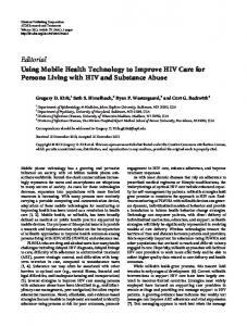
D. Proposed Reactive Scheme In this scheme, the MN has performed a handover before the context transfer is requested. It sends a move-notify message to the new P-CSCF containing the old P-CSCF IP address (see figure 6). The old P-CSCF is the one that validates the transfer. The New P-CSCF sends a Context Transfer Request message to the old P-CSCF. The old P-CSCF replies with a Context Transfer Message that contains the session information. Finally, after receiving Ack, the old P-CSCF updates S-CSCF routes information by sending Route update and receives 200 ok. In this scheme context transfer does not run simultaneously with MIPv6 handover procedure. After sending a movement notification to the new P-CSCF and create tunnel between old and new AR, the New P-CSCF sends request massages for session and QoS context to old PCSCF. The old P-CSCF sends the QoS request to the old AR and receives QoS context from it. When New P-CSCF receives QoS context from old P-CSCF, forwards it to the S-CSCF and New AR. After this procedures, when MN sends Re-Invite message to the CN, the QoS check and finalized at the new AR, CN's P-CSCF and new P-CSCF. MN IMS Network N-AR
O-AR
MN- MIPv6
HA
CN IMS Network O-P_CSCF
N-P_CSCF
S_CSCF
P_CSCF
CN-MIPv6
Data Flow RtSolPr PrRtAdv MoveNotify (New IP) FNA [FBU] FBU FBack Forward Packet
buffering
Session Context REQ QoS-Context REQ
QoS Context REQ Session-CT
QoS Context
QoS Context
CT-Ack QoS Context
QoS Context
QoS Context
QoS Context
QoS Context
Forward Packet Route Update 200 OK
BU-HA BAck BU-CN BAck Register 200 ok Re-Invite
Re-Invite
Re-Invite
200 OK
Re-Invite
Authorize QoS Resources
Authorize QoS Resources
200 OK
200 OK
200 OK
Authorize QoS Resources
Data Flow
Figure 6. Proposed Reactive FMIPv6 handover in IMS network Figure 4. Proposed Predictive FMIPv6 handover in IMS network
The Proposed Reactive FMIPv6 handover Timing Diagram in IMS network is shown in fig 7.
Figure 7. Time diagram for Proposed Reactive FMIPv6 handover
IV.
PERFORMANCE EVALUATION
In this section we evaluate the handover delay for the two proposed schemes and compare with the delay of the original MIPv6 in IMS. The analysis is based on a simple model presented in [9] that takes into account the delay of the different entities involved in the handover procedure. For simplicity, we consider the model illustrated in Fig. 8. Table I describes the notations which are used in this model. We assume that the delays are considered symmetric and Tmr < Th. We do not consider the time needed by DAD process and Return Routability procedure, also the processing and queuing times are not considered.
In standard IMS-MIPv6, the handover is performed as follows: first the MN sends router solicitation to all ARs in its domain and receives router advertisements from them, then, selects one of them to migrate. Afterward, the MN obtains a new CoA which takes 2Tnar. Then the MN sends BU to HA and CN and receives Back from them, which takes 2Th + 2Tmc. Finally the MN should register in the new IMS network, and Re-invite the CN; these procedures take 4Tnp + 8Tmc. Therefore the overall delay for the standard IMS-MIPv6 handover would be: Tst = 2Tnar + 2Th + 10Tmc + 4Tnp
(1)
In the proposed predictive scheme the handover procedure starts in the same way as for standard scheme with proxy router solicitation/advertisement which takes 2Toar. The MN then sends Move-Notify that contain new MN’s IP address, to the old P-CSCF, which takes Top. The MN sends an FBU to the old AR, which takes Toar. The ARs, then, exchange HI and HAck, which takes 2Tonar. The old AR sends an FBAck to the new AR and to the MN, which takes at most Toar. At the same time the old P-CSCF sends Move-Notify followed by contexttransfer to the new P-CSCF that contains current session information. After receiving context, the new P-CSCF sends context-transfer Ack to the old P-CSCF. At this time the old AR sends his QoS context to the old P-CSCF and the old PCSCF sends the QoS context to the new P-CSCF. Processing the received data, the node transmits the Context to the SCSCF and the CN’s P-CSCF. Afterward the CN’s network returns the modifies QoS context to the new P-CSCF and new AR Consequently, the old P-CSCF sends route update to SCSCF and receives 200 ok. These procedures proceeds concurrently with the handover process avoiding extra latency. After that, the MN sends an FNA to the new AR, which takes Tnar. Then the MN sends BU to HA and CN and receives Back messages from them, which takes 2Tha + 2Tmc. Finally the MN should re-register in the new IMS network, and Re-invite the CN; these procedures take 2Tnp + 2Tmc. So the total delay for the proposed Predictive IMS-FMIPv6 handover would be: Tprd = 4Toar + Top + 2Tonar + Tnar + 2Th + 4Tmc + 2Tnp (2)
Figure 8. Simple model for analysis
TABLE I.
NOTATIONS USED IN FIG. 6
Notations
Description (Delay between)
Tmr Toar Tnar Tonar Top Tnp Tonp Th Tops Tnps Toaop Tmc
The MN and the radio access network The MN and the old AR MN and the new AR The OAR and the NAR The MN and the old P-CSCF The MN and the new P-CSCF The old P-CSCF and the new P-CSCF The MN and its HA The old P-CSCF and the S-CSCF The new P-CSCF and the S-CSCF The old AR and the old P-CSCF The MN and the CN
In the proposed reactive scheme the handover procedure starts in the same way as standard scheme handover, with proxy router solicitation/advertisement which takes 2Toar. The MN, then, sends Move-Notify that contain new MN’s IP address to the new P-CSCF, which takes Tnp. At this moment the MN has moved to the new AR and has not received an FBAck. Consequently, it sends an FBU encapsulated in an FNA via the new AR to the previous AR. The previous AR sends back an FBAck to the new AR and starts forwarding packets to the new AR, if the new CoA is accepted. This procedure takes Tnar + 2Tonar. Then, the new AR delivers the forwarded packets immediately to the MN. After that, the new P-CSCF sends session and QoS context request to the old PCSCF and it transmits the QoS context to the old AR. The old P-CSCF sends session information to the new P-CSCF by Context-transfer and receives ACK after. At this time the same predictive procedure runs, which take 2Toaop + 2Tnps + (Tnp - Tnar) + 3Tonp. Next, the old P-CSCF sends route update to S-CSCF and receives 200 ok. This procedure takes 3Tonp +
2Tops. Consequently the MN sends BU to HA and CN, and receives Back from them, which takes 2Tha + 2Tmc. Finally the MN should re-register in the new IMS network and Re-invite the CN; these procedures take 2Tnp + 2Tmc. As the result, the delay for the proposed Reactive IMS-FMIPv6 handover would be: Trac = 2Toar + 3Tnp + Tnar + 2Tonar + 5Tonp + 2Tops + 2Th + 4Tmc + 2Toaop + 2Tnps + (Tnp - Tnar)
(3)
As mentioned before, in the Predictive scheme, the session and QoS context transfer procedures are performed simultaneously to MIPv6 handover and don’t cause excessive latency. However, the reactive scheme for QoS adds some latency that shown in (3).
VI.
CONCLUSION
In this paper, In order to improve the performance of the handover procedure, we proposed two handover schemes for IMS networks over MIPv6. To lessen the handover latency, the predictive and reactive proposals make use of context transfer between the old P-CSCF and the new P-CSCF. The session state information and QoS information transfer prior to the handover decrease the total time needed for the transactions of the handover process. We investigated the performance of these schemes and compared them with the standard IMS handover without context transfer procedure. Our performance evaluation implies that shorter handover latency is achieved as fewer messages are required for the re-register and re-invite of the CN, and for the session re-establishments. REFERENCES
V.
NUMERICAL RESULTS
In this section, we present the numerical performance evaluations for the standard and the two proposed schemes. To evaluate the disruption time, we set Tmr = 10 ms as in [9] and [7]. Also, we assume Toar = 11ms, Tonar = 5ms, Top = 15ms, Tonp = 7ms and Tops= 10ms. The delay introduced by the Internet depends on the number of routers and the type of links in the path of datagram transmissions. For this reason, we assume the one-way Internet delay over the wired network to be constant and equal to 100ms. Therefore, we assume Th = 116ms, Tmc = 128ms and Thc = 114ms. A. Impact of old to new P-CSCFs Delay Fig. 9 shows that as the delay between the old P-CSCF and the new P-CSCF is increasing, the disruption time for the proposed predictive scheme would be the lowest. This augmentation is enhanced for the higher values of the old to new P-CSCF delay. Moreover, this figure adopts that the Disruption time rises monotonically as the old to new P-CSCF delay increases.
Figure 9. Disruption time versus delay between the old and the new PCSCFs
[1]
D. B. Johnson, C. E. Perkins, and J. Arkko, “Mobility support in IPv6,” IEFT RFC 3775, June 2004. [2] R. Koodli, Ed, “ Mobile IPv6 Fast Handovers,” IETF RFC 5268, June 2008. [3] H. Soliman, C. Castelluccia, K. El-Malki, and L. Bellier, “ Hierarchical Mobile IPv6 (HMIPv6) Mobility Management,” IETF RFC 5380, Oct. 2008. [4] 3GPP TS 23.228 V8.3.0, “IP Multimedia Subsystem (IMS); Stage 2”, Jan. 2007. [5] K. Lynggaard, E. Vestergaard, H-P. Schwefel and G. Kuhn, “Optimized Macro Mobility within the 3GPP IP Multimedia Subsystem”, IEEE, 2006. [6] T. Renier, K. L. Larsen, G. Castro and H-P. Schwefel, “Mid-Session Macro-Mobility in IMS-based networks” IEEE, Vehicular Technology Magazine, March 2007. [7] H. Fathi, S. Chakraborty, and R. Prasad “Optimization of Mobile IPv6Based Handovers to Support VoIP Services in Wireless Heterogeneous Networks”, IEEE Transactions on Vehicular Technology, vol. 56, no. 1, Jan. 2007. [8] J. Kempf, “Problem Description: Reasons For Performing Context Transfers Between Nodes in an IP Access Network”, IETF RFC 3374, September 2002. [9] J. Loughney, M. Nakhjiri, C. Perkins and R. Koodli, “Context Transfer Protocol (CXTP)”, IETF RFC 4067, July 2005. [10] R. Farahbakhsh, M. Varposhti, N. Movahhedinia, “Transmission Delay Reduction in IMS by Re-registration procedure modification”, IEEE, NGMAST, 2008. [11] 3GPP TS 29.208 V6.7.0, “End-to-end Quality of Service (QoS) signalling flows (Release 6)”, Jun. 2007.