The PSoC is microcontroller with some significant differences that make it useful
in a laboratory ... The PSoC has three classes: PSoC 1, PSoC 3 and PSoC 5.
Using Cypress Programmable System on a Chip (PSoC) Introduction The PSoC is microcontroller with some significant differences that make it useful in a laboratory setting. Traditional microcontrollers are quite powerful single purpose devices. They are like a small computer on a chip with all of the resources on board (albeit limited). In many ways, much of what one might do in electronics can be replaced by a microcontroller with digital processing. Microcontrollers have a number of general purpose digital inputs and outputs. They sometimes have analog to digital converters of varying precision. They may have pulse width modulators, digital to analog converters. The PSoC families have all of these and more. What they have that makes them very different from traditional microcontrollers are reconfigurable analog and digital blocks. The PSoC is a hybrid device. It is configured at programming (and the tricky can have it reconfigure itself) to have specific use digital and analog components. So, for example, you can configure the device to have a programmable gain amplifier or an instrumentation amplifier attached to the pin, removing the need for active analog components outside of the chip itself. This can result in a huge simplification of circuitry when building instrumentation. The PSoC has three classes: PSoC 1, PSoC 3 and PSoC 5. PSoC 1 is the oldest part of the family. It has a slower 8-bit core and more limitations. However, it does come in dual inline packages which is simpler if one is creating stand-alone circuit boards. Even within PSoC 1 there are variations that include 8 pin packages up to 28 pin packages. In IPFW classes we use the Cy8c29 series principally because we use the dual inline packaging when creating circuit boards. Your kits include the Cy8c28 series PSoC 1. These have the benefit that they can also use “capsense” which is capacitive buttons and sliders, much like used on tablet screens these days. In this workshop we will start with several PSoC 1 circuits, and hopefully finish with PSoC 5.
Differences between the PSoC 1, 3 and 5. The PSoC 1 has an 8 bit processor, a maximum of 32 kb of flash memory used for storage of firmware, 2kb of sram, and the ability to have A/D converters up to 14 bit precision. PSoC 1 have the ability to do analog low pass and band pass filtering which is not present in the 3 or 5 series. The PSoC 3 also has an 8 bit processor, but it is approximately 8 x faster. It has greater flash storage and ram. It has higher precision A/D (up to 20 bits) and it is possible to create new digital elements using Verilog. It can have digital signal processing abilities and built in USB. The PSoC 5 is very similar to the PSoC 3, adding a 32 bit processor, more memory and more digital and analog capabilities. The beauty of the system is that the programs you create are very similar for each of the series and it is not terribly difficult to change from one to the other. One of the best resources for learning to use the PSoC is the Cypress website with video tutorials and application notes. I particularly like the Cy8ckit-001 manual (http://www.cypress.com/?docID=38385) as a good starting point. Another good resource is the Cypress University Alliance (http://www.cypress.com/?id=1163&source=home_support).
Context It is important to understand the context of my use of these devices. Electronics is an experimentalist’s tool. I see the ability to create instrumentation as a very important component to being an experimentalist. For that reason our students get experience using the machine shop and with construction of devices. In particular, I teach a class on electronic instrumentation. In this class we cover the basic types of electronic instruments (such as lock-in amplifiers) and signal processing. Most importantly, students must build a working instrument and then use that instrument to perform an investigation. When they are creating an instrument, they are having to build mechanical components. They have to design and etch a circuit board, populate it, solder the components. Test it. Box it. Use it. Much of what we do revolves around the PSoC. On to the fun!
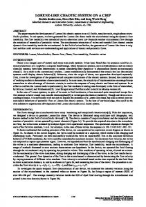
Hello world of Microcontrollers: blinking LED. 1. Open PSoC Designer 2. Enter a name for the project 3. For device, choose CY8C28645-24LTXI. If you wish, you can look at the catalog and see what other devices are available. Choose “C” as the ‘Main’ file. Note that clone project lets you copy a project and change the device for which a project is targeted. 4. You are presented with an overwhelming number of options. What you see are the digital and analog blocks available for configuration.
The global resources are on the upper left. This includes various clock settings. Of particular importance are the user modules on the lower right of the screen. 5.
We will simply set up a direct preliminary test: First go to Misc Digital in the user modules. Drag the LCD into the chip. It adds nothing to the chip but configures the ports. On the left side there is a parameters window (which can also be found if you select the LCD in the workspace explorer on the upper right). Go to LCDPort and change it from none to port_2. This attaches the LCD to the device. 6. Now go to PWMs and drag the PWM8 on the screen. Notice that it adds something to the digital blocks. This is the pulse width modulator. Now we have to configure the PWM to do what we want. 7. We need to set the clock. We need to set the period. We need to set the pulse width. I want a slow clock for this so I choose VC3. The system clock is 24MHz. VC1 is the system clock divided by some value – by default 16. VC2 is VC1/N, where N is 16 by default. VC3 is set to VC2 (VC3 source)/some value (default 256). Therefore VC3 is 24MHz/16/16/256 = 366 Hz. In the parameters section on Left of the PWM, I set the period to be 100. This is 100 clock pulses
which means that the frequency will be about 3.66 Hz. I set the pulse width to 50 which is about 50% duty cycle (half the time on, half the time off) ((pulsewidth+1)/period+1))
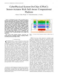
8. Now we need to connect the output of the PWM to an output. In either the parameters or on the graphical chip click on compare out and set it to row 0 output 3. Then you can go to the look up table and connect the output to a global bus (click on one f the little boxes on the chip representation. This allows you to connect to the bus. Click on the bus connection and you get
a dialog that lets you connect directly to a pin. Choose Port_1_7.
9. Now we are ready to write the code. Go to the directory in workspace explorer and expand it to show the source files directory. Double click on main.c 10. Now all we have to do is write some code to get things working. First thing to note is that if you right click on any user module in the workspace explorer you can pull up the data sheet that describes the device and the necessary programming. As a shortcut, I will list the necessary commands: First, all user modules have a common command to make them start: if you look in the workspace explorer, you see a user module name such as “LCD_1”. You then use the command in main.c to be “user module name”_Start(); (case sensitive, semi colon required). So for the LCD you type LCD_1_Start();. For the PWM you enter PWM8_1_Start();. Now let’s send something out to the LCD. Enter LCD_1_PrCString(“Hello World!”); That should do it for coding.
11. 12. 13. 14.
The most common mistake is to forget to use the correct module name and then to forget to start the module in firmware. On the board, run a wire from P1_7 to one of the LED’s. Hook the programmer up to the module Go to Build menu in PSoC Designer and Build the project. Note – you must always perform at least one build before trying to compile. Go to program and start the programmer and program the device.
Now we are ready for more complex programs.


![[PDF] CY8CKIT-050 PSoC® 5 Development Kit Guide - Cypress](https://m.moam.info/img/260x300/pdf-cy8ckit-050-psoc-5-development-kit-guide-cypre_59d179cd1723dd896eb01ded.jpg)