most notably 14CFR 25.1309 [1]. This compliance ..... existing standards, such as the AC 25-11A [15]. The .... [4] FAA AC 20-170 â Integrated Modular Avionics.
USING DESIGN PATTERNS FOR SAFETY ASSESSMENT OF INTEGRATED MODULAR AVIONICS Humberto Luiz Valdivia de Matos, Adilson Marques da Cunha, Luiz Alberto Vieira Dias Aeronautics Institute of Technology (ITA), Sao Jose dos Campos, SP, Brazil
Abstract In commercial aircraft, safety assessment uses a combination of top-down and bottom-up techniques. This is performed for every system in each aircraft installation. Since several functions and sub-systems are common to different aircraft models, there is the need to consider reusing components and safety artifacts across several platforms. This necessity has become even more evident with the introduction of the Integrated Modular Avionics (IMA) concept. There is an increasing interest in developing design patterns in safety-critical systems. This paper provides an investigation of how SysML/UML design patterns can be used to assess the safety of IMA systems in a modular manner, while maintaining compliance with the existing civil aircraft certification guidelines. A case study is provided for a generic avionics system based on the IMA concept, fulfilling safety requirements for civil avionics.
Even before the advent of IMA, it was an open issue the assessment of reuse of software, Line Replaceable Units (LRUs), and entire subsystems within different application domains.
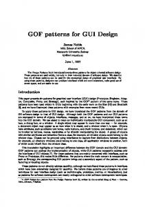
Traditional safety assessment approach in commercial aircraft systems An overview of the framework defined in [2] and [5] is shown in Figure 1. This paper is focused on the development of system architectures and its associated components. Therefore, greater emphasis will be placed on the highlighted activities.
Introduction Aircraft systems in commercial aviation are required to show compliance with safety regulations, most notably 14CFR 25.1309 [1]. This compliance is normally shown using guidelines found in SAE ARP 4761 [2], which is a generic process applicable to all types of aircraft systems, from purely mechanical hydraulic systems to software intensive systems like avionics or fly-by-wire systems. The Integrated Modular Avionics (IMA) is defined in [3] as a shareable set of flexible, reusable and interoperable resources that form a platform to host applications performing aircraft functions. A key concept in this definition is resource reusability. This concept was further emphasized by the FAA in [4], with the introduction of the process of incremental acceptances for reusable IMA components.
Figure 1. ARP 4754A/ARP 4761 Safety Assessment process model (adapted from:[2][5])
This framework starts with an assessment of aircraft-level functions, such as provide lift and drag, control aircraft path, or provide thrust. This activity is the Aircraft FHA (Functional Hazard Assessment). This initial evaluation has little to do with the design of the aircraft systems themselves and more with the aircraft operational profile and its aerodynamic characteristics. The next step is to determine the system-level functions and their impact on the aircraft, crew and/or occupants, should this function not operate properly. The System FHA classifies system-level hazards in five different categories (No Safety Effect, Minor, Major, Hazardous, Catastrophic). For each of these categories, safety objectives are defined and flown down to the system design. The higher the impacts of a failure condition in the aircraft safety, the stricter are these safety objectives. For example, a failure condition classified as Catastrophic in the System FHA must be shown to be extremely improbable (probability below 10-9 per flight hour) and must not result from a single failure. Safety objectives from ARP 4761 [2] are summarized in the following table. Table 1. ARP 4761 [1] Safety Objectives summary Hazard Class
Safety Objectives
Catastrophic (CAT)
Extremely Improbable (Prob < 1E-9 per flight hour) No single failure DAL A Extremely Remote (Prob < 1E-7 per flight hour) DAL B Improbable (Prob < 1E-5 per flight hour) DAL C
Hazardous (HAZ) Major (MAJ)
Minor (MIN)
No Safety Effect (NSE)
[2]. Though the definition of system-level safety objectives from the System FHA is straightforward, defining the system architecture to achieve these safety objectives is not. Definition of system architecture is performed in an iterative fashion. The systems architect defines an initial architecture and a set of assumptions (including operational conditions and failure rate budgets), then runs one of the quantitative analyses (most usually Fault Tree Analysis) to have a preliminary estimate of the compliance with safety objectives. In many cases, safety objectives will drive major architectural decisions, such as the number of redundant channels and the monitoring strategy. Experienced system architects develop a set of heuristics based on previous designs that comply with the applicable requirements, including functional requirements, performance, and safety. Though useful, these heuristics are continuously challenged by the evolution in the safety objectives, system requirements, or technology. Moreover, as Kelly and McDermid [6] point out, this informal (ad hoc) reuse of safety case artifacts may be a source of a number of problems, including inappropriate reuse of safety arguments in different contexts, loss of knowledge, lack of consistency, and waste of resources, just to name a few. Integrated Modular Avionics Systems bring these reuse concerns to a new level. In traditional federated systems, an aircraft-level function such as Stall Protection would be allocated to a defined set of Line Replaceable Units (LRUs): Angle-Of-Attack (AOA) vanes, Stall Computers, a Stick Pusher, and an audio device (such as a horn), as shown in Figure 2.
Probable (Prob < 1E-3 per flight hour) DAL D No requirements
Demonstration of these objectives is performed using quantitative methods such as Fault Tree Analysis, Markov Chains or Dependency Diagrams
Figure 2. Example of a generic Stall Protection system using federated architectures
A manufacturer of a Stall Protection System would be able to sell the same set of components to several aircraft manufacturers, with minimal software adjustments (gains and thresholds, for example) for each different aircraft type. A number of safety artifacts, including Fault Tree Analyses (FTAs) and Failure Modes and Effects Analyses (FMEAs) would be used throughout the entire product line, as well as a large portion of the software certification documentation [2]. In an Integrated Modular Avionics system, this aircraft-level function could be deployed in a much different way. Instead of dedicated LRUs performing specific functions, generic hardware modules provide services for a range of different aircraft functions, as shown in Figure 3. These generic hardware modules may not even be manufactured by the same company that produces the Stall Protection application. For example, this means that such an application needs to be ported across several platforms for each customer.
Distributed IMA or Adaptive IMA systems will make this kind of question even more difficult to address.
Safety-related Design Patterns The software industry has been a long adopter of the Design Patterns concept, which had in Gamma [7] one of its early promoters. Douglass, in [8] and [9], enhances further the concept to include the specific needs of real-time systems, including safetycritical ones. Armoush [10] takes one step further to create representations of these patterns for SafetyCritical systems. Though there is extensive research on the application of design patterns in software development, Safety is a system issue, as pointed by Douglass [9], which means that the safety aspects of software cannot be treated separately from the other aspects of the system. This is true also in commercial aerospace systems. At the time of Douglass’ writings, however, the SysML specification was not available and the examples of design patterns were represented in UML, which tends to be software-centric. Other researchers like Kelly [6], Khalil et al. [11] use the GSN (Goal Structuring Notation) to represent these patterns. The objective in this paper is to use the OMG SysML to describe these patterns at the systems level and, if applicable, UML to represent allocations at the software level.
Pattern description structure Figure 3. Example of a generic Stall Protection system using IMA The implications for reuse in this case are much more dramatic. Significant portions of the application may be fully reused, including requirements and large parts of source code, but the safety analysis at the system and aircraft level (Tasks 3 and 4 of DO297 [3]) must be done nearly from scratch to accommodate the new context and hardware implementation. Moreover, the additional flexibility provided by IMA brings also new challenges to system architects: how can applications and functions be allocated throughout the IMA Platform in a way that satisfies the safety constraints at all times? Future trends like
Using the safety case pattern structure defined by Gamma [7] and Kelly and McDermid [6] as a starting point, some adjustments have been made to accommodate the specific processes of the ARP 4761 [2] framework and its safety objectives. This pattern description structure is described as follows: • Pattern Name The Pattern Name provides reference to the pattern itself in a concise, clear and unambiguous way. • System safety objectives This item describes the safety objectives to be accomplished by the system using this design pattern.
These objectives are driven by the system FHA, as shown in Table 1. A system may have one or more FHA failure conditions allocated to it (usually much more than one) and the combination of conflicting aspects (availability vs. integrity, for example) may drive the use of one safety design pattern rather than the other. In addition, it is important that this approach should be scalable to several layers of subsystems. A subsystem may be allocated to be part of the overall safety objective and another, usually simpler design pattern, may be applicable. • Also Known As This field refers to other names for which the design pattern may be known (across different domains, for example). • Pattern Structure This item presents the pattern structure in a SysML (for patterns at the system level) or UML (for patterns at the software level). • Participants / Collaborations This item provides the interactions of the system (or subsystem) with other actors. In commercial aerospace system, these actors may be the flight crew, passengers, maintenance, Air Traffic Control (ATC), weather, terrain, other aircraft-level functions (like flight dynamics or structural loads) and even other aircraft. These interactions are intimately connected with the Functional Hazard Assessment process described in ARP 4761 [2]. • Consequences This item provides the consequences of adopting the design pattern. Safety consequences may be, of course, the achievement (or not) of certain safety objectives in terms of availability or integrity. In the ARP 4761 context, this may be represented by a set of Fault Tree Analysis structures specific to that design pattern. With the fault trees come more assumptions such as additional requirements for crew procedures or maintenance checks. Additionally, other failure modes at the system level may appear as a consequence, which will have to be analyzed as well. For example, if triple channel redundancy is used to achieve 1E-9 availability, the
effects of a failure or malfunction in one or two of these channels shall be analyzed and fed back to the FHA. • Implementation This item provides some insight on the implementation of the pattern, including problems that may occur in specific scenarios. In an Integrated Modular Avionics system, the correlation between the abstract elements of the design patterns and physical components installed in the aircraft may not be straightforward. The examples in this paper will address these physical allocation restrictions as part of the design process. • Related Patterns This item provides references to other patterns that relate to similar safety issues.
Relevant Safety Design patterns for aerospace industry A brief review of some Safety Design Patterns found in literature is provided as follows: • Protected Single Channel Pattern (PSC) This lightweight safety design pattern has the advantage of being simple and inexpensive [8]. Though it is obviously not capable of supporting higher-level safety objectives, it is adequate for systems which loss or malfunction is not worse than Minor. In this pattern, protection mechanisms are added to the single actuation channel. One of the protection mechanisms is the input data validation. The SysML Internal Block Diagram, as shown in Figure 4, represents this Design Pattern. Douglass [8] mentions two variants of this pattern: open-loop and closed-loop. In the closed loop variant, a feedback block for the actuation is included. The results of this feedback are provided to the algorithm.
Figure 4. Protected Single-Channel Pattern
In many cases, it is possible to suppress the comparator and the switch and leave the task of channel selection to the users. For example, in case of altitude miscompare between pilot and copilot instruments, both pilots compare their information from their sensors with other data available on the flight deck to select the source most likely to be correct. Fly-by-wire or other systems in which the pilot is not on the loop, on the other hand, may not be able to rely on this strategy.
The design pattern itself does not establish whether its elements are allocated to hardware or software, but it is assumed in this case that they are allocated to a single channel and that no independence can be claimed between these elements. Being a single channel pattern, a failure in this single channel will cause loss of the entire system. • Homogeneous Duplex Redundancy Pattern (HDR) This design pattern [8], shown in Figure 5, provides a classical solution to increase availability against random hardware failures. Armoush [10] provides a discussion on the safety improvements of this pattern and the limitations related to the coverage of the comparator and the lack of tolerance to systematic faults which may affect both channels at the same time. In commercial avionics, the homogeneous redundancy pattern is widely used and even some aviation regulations specify equipment-level redundancy to ensure availability of some functions (for example, two communication radios in overwater operations – 14CFR 91.511 [12]). In the ARP 4761 framework, this pattern is adequate for situations in which a loss of function is classified as Major. However, this design pattern does not provide any solution to the integrity problem. If a fail-safe state does not exist (or if an inadvertent actuation of any channel is a hazard at the system level), then the malfunction of the system is caused by a malfunction of any channel. This will be referred to as HDR-NFS (Homogeneous Duplex Redundancy – No Fail-Safe). Otherwise, if a fail-safe state does exist, then the output will be only hazardous if both channels malfunction. This will be referred to as HDR-FS (Homogeneous Duplex Redundancy – Fail-Safe).
Figure 5. Homogeneous Duplex Redundancy Pattern • Heterogeneous Pattern (HeDR)
Duplex
Redundancy
The Heterogeneous Redundancy pattern [8] is very similar to the Homogeneous Redundancy pattern in terms of construction. However, it differs from the previous one because channels have dissimilar designs. This dissimilarity may be achieved by using diverse hardware and/or software implementations in each channel. When applied to software, this pattern is commonly referred to as NVersion Programming (NVP). Even greater robustness is achievable if each channel is based on different algorithms or physical phenomena. This improves robustness against implementation errors, but has a significant impact on development, maintenance and certification cost, as well as on overall system complexity. ARP 4761 and ARP 4754A do not assign quantitative probability values for design errors. Yet, these guidelines require qualitative analyses
(Common Mode Analyses) to evaluate the contribution of software or hardware design errors to the overall failure condition. In this scenario, the Heterogeneous Duplex Redundancy pattern is useful in showing compliance with safety objectives. One classic example of this pattern in avionics applications is the use of a standby indicator that is not the same design as primary displays. • Triple Modular (TMR)
Redundancy
• M-out-of-N Pattern (MooN) The M-out-of-N Pattern [6] is an extension of the Triple Modular Redundancy pattern. This pattern implements a voter in which the output will be the result a voting scheme of the outputs of N>3 redundant channels, as shown in Figure 7.
Pattern
The Triple-Modular Redundancy Pattern [8] is one extension of the Homogeneous Duplex Redundancy Pattern for systems with high safety objectives for both availability and integrity. Three modules processing the same data operate in parallel, while the outputs of each channel are voted in a “winner-takes-it-all” manner. This pattern is shown in Figure 6. Figure 7. M-out-of-N Redundancy Pattern This design pattern has a series of drawbacks for application in commercial aircraft systems. The first of them is that if homogeneous redundancy is used, there is no protection against design flaws and other common modes. Another is the enormous impact in recurring cost, weight and power requirements. And finally, the safety performance of this pattern will be driven by the voting element. Figure 6. Triple-Modular Redundancy Pattern As in the Homogeneous Duplex Redundancy Pattern, there is no protection for systemic faults or design flaws in each channel. The Triple Modular Redundancy Pattern may be further combined with the Heterogeneous Redundancy pattern to provide a three channel solution with dissimilarity, which can be shown to be adequate to meet the highest ARP 4761 safety objectives (1E-9) for both availability and integrity without being exposed to Common Mode Failures.
However, this voting pattern may be combined with other safety patterns in situations in which several sensors are available and the actuation channel needs to choose a value. • Monitor-Actuator Pattern (MA) The Monitor-Actuator Pattern [8][10] provides a solution for the integrity problem and is particularly adequate for situations in which a fail-safe state does exist. In this pattern, one channel is responsible for performing the end-to-end actuation, while the monitor channel compares the output of the actuator channel against the expected value and shuts the actuator off, if a discrepancy is found. This pattern assumes that loss of the actuation function is a less critical condition. In this type of system, the monitor channel usually contains a reduced version of the actuation
algorithm and is driven by a separate set of sensors. The same set of sensors may be used, but this introduces a common mode failure into the system. This pattern is shown in Figure 8.
• Recovery Block (RB) The Recovery Block pattern [10] is a software safety design pattern in which the outputs of multiple versions of the function are submitted to acceptance tests and if the primary version fails the test, a secondary (dissimilar) version is executed and submitted to the acceptance test. This design pattern has the advantage of reducing the amount of processing needed, when compared with NVP. However, it requires a suitable acceptance test to be developed, which may not always be possible in safety-critical systems. A related pattern is the Acceptance Voting (AV), in which N different versions of the same requirement are executed in parallel and subject to the acceptance testing and then voting.
Figure 8. Monitor-Actuator Pattern This design pattern is adequate for systems in which loss of function is a Minor failure condition, but erroneous operation has a higher criticality. One example application of this design pattern is for autopilot systems. Autopilot systems usually have low availability requirements (pilots should always be capable of flying aircraft manually), but must be protected against malfunctions that may put the aircraft in a hazardous condition, such as control surface hardovers or slowovers. As pointed out by Armoush [10], if a failure in the monitoring channel occurs, no result may be observed in the system until a second failure occurs in the actuation channel. This condition is a latent failure and must be avoided through periodic maintenance checks [8] and/or specific built-in-tests [10]. The Monitor-Actuator pattern has also some lighter-weight variants, such as the Sanity Check (SC) and the Watchdog (WD) patterns [8]. These variants are less expensive to implement and are often found as mitigation means for specific failure modes of hardware components (for example, a Watchdog being used to prevent a microprocessor freeze).
As with other diversity-related patterns (such as NVP and HeDR), the benefits of these patterns are related to the reduction of exposure to common mode events such as design errors. • 3-Level Safety Monitoring Pattern (3LSM) The 3-Level Safety Monitoring Pattern was originally created in the automotive industry [13] and is a combination of the Monitor-Actuator and Watchdog patterns [9]. As the name implies, this pattern consists of three levels implemented in a single hardware channel: Actuation, Monitoring and Control. The Actuation and Monitoring levels work similarly to a Monitor-Actuator pattern, while the Control level monitors the hardware integrity. An external Watchdog ensures proper command sequencing. • Safety Executive Pattern (SE) The Safety Executive Pattern [8] is a more complex pattern to address more complex scenarios in which a fail-safe state cannot be achieved simply by shutting off the primary actuation channel. In this pattern, if a failure or malfunction is detected in the primary actuation channel, the safety executive takes control and performs the transition to a safer condition, in which control can be handled to the failsafe processing channel, as shown in Figure 9.
Table 3. Assumptions for quantitative analysis
Figure 9. Safety Executive Pattern It is very common in aircraft designs that the flight crew acts as a safety executive based on monitors implemented in the avionics system. When an abnormal situation is detected (such as a cabin depressurization), the avionics system (acting as a monitor) alerts the flight crew, which then takes the appropriate action (for example, descend to a safe altitude) to avoid a hazardous scenario. As a matter of fact, there are examples in the industry of automated systems in which the autopilot performs this safety executive function in case of aircraft depressurization without any pilot involvement [14].
Assumptions for quantitative analysis During the Preliminary System Safety Assessment (PSSA) stage of ARP 4761, it is necessary to define failure rate budgets to system components, which are then passed to the suppliers of each element as requirements. In this work, the greatest concern is based on the architecture of system and the interrelationships between elements, instead of individual failure rates. The assumption is that individual modules have similar failure modes and failure rates and therefore the safety objectives of the system are to be achieved through the architectural decisions represented by the design patterns previously shown. For this analysis, generic quantitative failure rates have been assumed to support the Fault Tree Analysis effort, as shown in Table 3.
Event Loss (Failure) of an electronic unit Malfunction of an electronic unit Loss of an electrical power bus
Prob. 1E-4 1E-5 1E-5
Loss of an input sensor Malfunction of an input sensor Loss of an output actuator Malfunction of an output actuator
1E-4 1E-5 1E-4 1E-5
Conservatively, sensors and actuators were included as part of the channels. For simplicity, it was assumed flight duration of 1 hour and that all latent failures are detected by Power-up Built-InTests (PBIT) before every flight.
Application of Design Patterns For each of the Design Patterns described above, Fault Tree Analyses have been performed considering the safety objectives for Loss and Malfunction. The results are shown in Table 4. Table 4. FTA results for Generic Design Patterns Design Pattern Protected Channel (PSC)
Avail. 3.10E-4
Integr. 3.00E-5
Homogeneous Duplex Redundancy – No Fail Safe state (HDR-NFS) Homogeneous Duplex Redundancy – Fail Safe state (HDR-FS)
9.61E-8
6.00E-5
9.61E-8
9.00E-10
Triple Modular Redundancy (TMR)
2.98E-11
2.70E-9
Monitor-Actuator (MA) Safety Executive (SE)
3.40E-4 1.58E-7
6.00E-9 3.00E-5
Single
The Heterogeneous Duplex Redundancy (HeDR) was not included in the Table as it quantitatively yields the same results as the HDR. However, it may be used in situations in which protection against design errors is needed.
[MainPattern]+[number_of_instances][SubPattern] For example, a combination of the Triple Modular Redundancy pattern in which 2 channels are a Monitor-Actuator pattern is referred to as TMR+2MA. Some relevant combinations have been calculated and are presented in Table 5. Table 5. FTA results for Combined Design Patterns Design Pattern
Avail.
Integr.
HDR-NFS+1MA HDR-NFS+2MA TMR+1MA TMR+2MA
1.05E-7 1.16E-7 3.27E-11 3.58E-11
3.00E-5 1.20E-8 9.00E-10 6.36E-12
TMR+3MA
3.93E-11
1.08E-16
Table 6 presents a list of recommended patterns for each safety objective. In some cases, more than one pattern is adequate for the objective and the designer is expected to combine the generic design pattern with the specific needs of the system being developed.
Table 6. Design Patterns per Safety Objective Availability CAT CAT
Integrity
As it can be seen from Table 4, the use of a single design pattern is not capable of meeting the safety objectives for the highest criticality functions, particularly in duplex redundancy cases without a fail-safe state. It is necessary to provide combinations of design patterns to successfully address these safety requirements. For example, in a dual or triple redundancy system, having one or more channels protected by a Monitor-Actuator scheme increases the integrity and maintains the overall availability. This combination of patterns is represented in the following notation:
HAZ
MAJ
MIN
HAZ
TMR+1MA HDR-FS
TMR
TMR
TMR
Case Study: System
MAJ
MIN
HDR-FS
HDR-FS
TMR+1MA HDRNFS+2MA
MA
HDR-FS
HDR-FS
HDR-FS
HDRNFS+2MA
HDRNFS+2MA
MA
HDR-FS
HDR-FS
HDR-FS
HDRNFS+2MA
MA
MA
HDR-NFS
HDR-NFS
PSC
SE
SE
Generic
IMA-based
This section presents the use of Design Patterns for the safety assessment of a generic avionics system based on an IMA platform. For this example, the environment of a fixedwing 14CFR Part 25 aircraft was chosen in which the safety objectives and methods defined in ARP 4761 [2] apply. Even though this simple generic system lacks the completeness of a real-world avionics installation, it is a convenient means of demonstrating the use of Design Patterns for system safety assessment.
System overview The Generic Avionics System is a real-time distributed computing system that is responsible for receiving data from the aircraft, processing it and providing indications and alerts to the flight crew. The main functionalities of this Generic Avionics System in this case study are described as follows: • Provide primary flight indications to flight crew (attitude, altitude, airspeed, and heading); • Provide navigation information to flight crew (e.g. VOR navigation);
• Provide communication capability to flight crew; Four electronic displays are provided for display of information, as well as an additional standby indicator. This Generic Avionics System follows the Integrated Modular Avionics concept and is built around a platform composed of generic modules, which are then populated with application software to support the required functions. Specialized hardware, such as air data computers, angle of attack vanes, inertial sensors, radios and data concentrators are connected to the core platform and ensure proper flow of information with the outside world. The Block Definitions Diagram of the Generic Avionics System is shown in Figure 11.
Figure 11. Block Definitions Diagram (BDD) for the Generic Avionics System
System Functional Hazard Assessment As defined by ARP 4761 [2], a Functional Hazard Assessment is performed to this generic system. For simplicity, a reduced set of failure cases were analyzed and classifications were driven from existing standards, such as the AC 25-11A [15]. The results of the FHA are shown in Table 7. Table 7. FHA summary for the generic avionics system Failure Condition
Haz. Class
Failure Condition
Haz. Class
Loss of all attitude displays, including standby display
CAT
Display of misleading attitude information on both primary displays
CAT
Display of misleading attitude information on one primary display
HAZ
Loss of all airspeed displays, including standby display
CAT
Display of misleading airspeed information on both primary displays
HAZ
Loss of all barometric altitude displays, including standby display Display of misleading barometric altitude information on both primary displays
CAT
Non-restorable loss of display of all navigation information coupled with a total loss of communication functions
CAT
Loss of display of all navigation information Display of misleading navigation information simultaneously to both pilots
MAJ
Loss of all communication functions
MAJ
CAT
HAZ
Each of the failure conditions presented in Table 6 can be understood as hazard states to be avoided. Using the safety objectives from Table 1, this provides targets for the systems architect to design a system that meets the overall safety objectives. The safety objectives of availability and integrity are then used to select a design pattern. These targets are detailed in Table 8. Table 8. Safety objectives per function Function Attitude Airspeed1
Avail. CAT HAZ
Integr. CAT CAT
Pattern TMR+2MA TMR+2MA
Altitude1 Navigation2
CAT
CAT
MAJ
HAZ
TMR+2MA HDRNFS+2MA
Communication2
MAJ
MIN
HDR-FS
Notes: (1) Airspeed and Altitude indications use the same sensors, so the actual design is driven by the higher-criticality parameter; and (2) The combined objective for Total Loss of Navigation and Communication will be discussed later in this paper.
Allocation of functions to modules using design patterns The following sections contain examples of how design patterns were used in this study to allocate functions to specific modules. Primary Flight Information (Attitude, Altitude, Airspeed) The display of primary flight information to the flight crew can be decomposed in the same stages used in the Design Patterns representation for a Protected Single Channel, as shown in Figure 12. Sensors measure physical phenomena, which are then processed and validated at a first stage. This data is then transformed, using information from other sources. An output processing function transforms this information into a graphical format that is sent through an actuator (a display) to the external world. Feedback from the Display can be obtained with an Actuation Monitoring activity. In case the display does not present the desired symbols (due to an internal malfunction), the channel may be reset and/or may declare a failure.
Figure 12. Activity Diagram of the Primary Flight indication parameters In order to achieve the CAT objectives for availability and integrity, the Triple Modular Redundancy with 2 Monitor-Actuator channels (TMR+2MA) design pattern was chosen. Even though the TMR+1MA could have been chosen in terms of safety objectives, it is convenient – due to human factors aspects – to have symmetric processing channels for pilot and copilot. As a matter of fact, provided that these parameters are required to be shown in a specific arrangement to the flight crew (14CFR 25.1321 [16]), it makes sense to have a single application set up as the output processing channel of the PFD (Primary Flight Display). Being a triple-redundancy system, three input sensors were chosen, each one allocated for each channel (pilot/copilot/standby). A monitor-actuator pattern was applied in the PFD drawing application, with an independent monitor (running on a separate hardware module) checking feedback from the actuator (which is the display itself). In this example, it is assumed that all symbology is calculated in the application within the IMA and sent to the displays using a standard video bus such as ARINC 661 or
ARINC 818. This architecture is shown in the SysML Internal Block Diagram in Figure 13.
using guidance from the faulty channel. This drives the need of using the HDR-FS+2MA design pattern. As described in the previous sections, this pattern is a combination of the homogeneous dual-channel redundancy with a monitor-actuator scheme in each channel. In the IMA example presented in this paper, the Monitor-Actuator pattern can be allocated to two separate applications running in separate modules. In order to detect malfunctions of NAV sensors, data from the cross-side NAV radio is routed through the IMA databus. This architecture is shown in Figure 14.
Figure 13. Primary Flight Information architecture Communication and Navigation As mentioned above, the highest hazard identified for this set of functions is the NonRestorable Loss of Navigation and Communication, which is classified as Catastrophic. Being two different functions, with some degree of independence from each other, this failure condition can be addressed by a Heterogeneous Duplex Redundancy pattern, in which one channel is responsible for Communication and the other for Navigation. In this specific case, it is possible to assume that a fail-safe state does exist, as a malfunction in Navigation channel does not affect the Communication channel and vice-versa. In Table 8, the Communication function was assigned a HDR-FS pattern. This is sufficient for the Communication safety objectives, provided that a malfunction in a single communication channel (for example, a radio) is not considered a hazard for the function. The other radio remains operative and can be used if needed. In order to maintain maximum independence from the Navigation function, the Communication was allocated completely outside the IMA Platform, with radio tuning being performed directly from a tuning panel to the radio. For the Navigation function, on the other hand, a malfunction in a single channel is considered a hazard for the function, provided that pilots may be
Figure 14. Navigation and Communication architecture
Conclusions In this paper, a brief study on the applicability of design patterns for the safety assessment of commercial avionics systems was presented. It was shown that it is possible to combine the safety design patterns proposed by Douglass and Armoush with the standard safety assessment guidelines used in the commercial aircraft systems domain. It was also shown that some safety objectives might require more than one pattern.
Suggestions for future work It is the authors understanding that the application of safety design patterns in the aerospace industry is still at its early stages. The performed analyses may be enhanced with the addition of new
patterns identified in real-world projects, especially those based in IMA platforms. Moreover, softwarespecific patterns were not addressed in this quantitative study, but they are relevant in situations in which sensor redundancy is separately treated from channel redundancy. An additional suggestion for future work is to apply this process to other types of aircraft systems, including fly-by-wire, engine control, and air management systems, for example.
References [1] 14CFR 25.1309 - Equipment, systems, and installations. Code of Federal Regulations – Title 14 (Aeronautics and Space). Federal Aviation Administration, 1970. [2] ARP 4761 -Aerospace Recommended Practice Guidelines for Safety Assessment of Commercial Aircraft Systems. Society of Automotive Engineers, 1996. [3] RTCA DO-297 – Integrated Modular Avionics Development Guidance and Certification considerations. [4] FAA AC 20-170 – Integrated Modular Avionics. Federal Aviation Administration, 2010. [5] ARP 4754A -Aerospace Recommended Practice Guidelines for Development of Civil Aircraft and Systems. Society of Automotive Engineers, 2010. [6] KELLY, T. P., McDERMID, J. A, Safety Case Construction and Reuse Using Patterns. SAFECOMP 1997 - The 16th International Conference on Computer Safety, Reliability and Security. Springer, 1997. [7] GAMMA, E. et al. Design Patterns – Elements of Reusable Object-Oriented Software. Addison Wesley, 1998.
[8] DOUGLASS, B. P. Real-Time Design Patterns: robust scalable architecture for Real-Time systems. Addison-Wesley, 2003. [9] DOUGLASS, B. P. Doing Hard Time: developing real-time systems with UML, objects, frameworks and patterns. Addison-Wesley, 1999. [10] ARMOUSH, A. Design Patterns for Safety Critical Embedded Systems. PhD Thesis. RheinlandWestfalen Technische Hochschule (RWTH), Aachen, 2010. [11] KHALIL, M., SCHÄTZ, B, VOSS, S. A Pattern-based Approach towards Modular Safety Analysis and Argumentation – European Real-Time Systems Conference (ERTS) 2014. [12] 14CFR 91.511 - Communication and navigation equipment for overwater operations. Code of Federal Regulations – Title 14 (Aeronautics and Space). Federal Aviation Administration, 1989. [13] US Patent 5880568: Method and arrangement for controlling the drive unit of a vehicle, March 1999. [14] US Patent 4314341A –Aircraft Automatic Pilot with Automatic Descent Control Apparatus. Sperry Corporation, 1980. [15] AC 25-11A - Advisory Circular: Electronic Fight Deck Displays. Federal Aviation Administration, 2007. [16] 14CFR 25.1321 – Arrangement and visibility. Code of Federal Regulations – Title 14 (Aeronautics and Space). Federal Aviation Administration, 1989.
33rd Digital Avionics Systems Conference October 6-10, 2014