data rates limited only by the processing speed of the end host. To enable this dial-up ... should implement signaling protocols for handling call setup ... Setup. Success. Success. Success. Switched circuit. Customer premises buildings. LLSP.
Using dial-up lightpaths for high-speed access Malathi Veeraraghavan Polytechnic University Abstract- We propose a dial-up optical access architecture that allows an end host to dynamically request and receive a high-speed circuit for connection to its Internet Service Provider’s router. We carry out an analytical comparison of the current leased-line architecture and our proposed dial-up architecture for access networks. It shows significant capacity savings, for example, savings of 39% at 50% traffic load for a call blocking probability of 0.5% assuming 3000 hosts share the optical link. With a call queueing model, we demonstrate that even if the circuit is held for long durations in the dial-up architecture, bandwidth savings are possible over the leased-line architecture. I. INTRODUCTION
Different types of optical networks have been realized using newly invented optical communications components. Specifically, optical communications components are of two types: optical link components and optical switching components. Examples of optical link components are transmitters and receivers, Wavelength Division Multiplexing (WDM) multiplexers and demultiplexers and WDM passive star couplers that enable broadcast optical links. Examples of optical switching components are tunable transmitters and receivers, WDM circuit switches, such as programmable Optical Add/ Drop Multiplexers (OADMs), Optical Crossconnects (OXCs), and photonic packet switches. We classified optical networks into four types in [1]: optical-link networks, broadcast-and-select networks, wavelength-routed (WR) networks [2]-[4] and photonic packetswitched networks [5], based on the type of optical switching components used. Among these, we focus on applications for optical-link networks and WR networks. Our classification in [1] defines that all switches in optical-link networks are only electronic, while in WR networks, end-to-end paths can traverse only optical switches or a hybrid of some optical and some electronic switches. Also, while optical-link networks can include end-to-end paths that traverse only circuit switches, only packet switches, or a combination of both, WR networks necessarily include optical circuit switches and hence end-to-end paths can consist of either all circuit switches, or a hybrid of circuit switches and packet switches. We propose a new application, dial-up service, for opticallink networks and WR networks that use only circuit switches (electronic and/or optical). Currently, such networks are used to provide “leased-lines,” i.e., circuits/lightpaths provisioned across these networks. Section II describes this current architecture. Section III describes our proposed dial-up “switched” architecture for usage in access networks. This architecture will provide individual end host users dedicated high-band-
1
Dimitris Logothetis Lucent Technologies width access links. Section IV presents an analytical comparison of the leased-line and dial-up architectures. Finally, we summarize the paper in Section V. II. C URRENT ACCESS A RCHITECTURE: LEASED LINES
Two recent market phenomena have led to the deployment of circuit-switched optical-link networks and WR networks for access. First, optical fiber reach has been extended to highrise/large enterprise buildings and Multiple Tenant Units (MTUs) in metropolitan areas. Second, low-cost SONET/ WDM multiplexing/switching systems referred to as “nextgeneration SONET systems” are being sold to enterprise customers to allow multiple customers within a building to multiplex their voice T1s, data T1s and ethernet on to SONET/ WDM leased lines [6]. An example of such an access optical network architecture is shown in Fig. 1 with the leased lines shown in Fig. 2. SONET circuits, such as OC1, OC3, OC12, ISP/Telephone service provider
Customer premises building ethernet switch/router
PBX
ethernet switch/router
PBX
ethernet switch/router
PBX
ISP IP Router
SONET/WDM Leased-Line multiplexer/switch Service Provider (LLSP) SONET switch or WDM switch
SONET/WDM multiplexer/switch
Optical fiber
DS0 based switch
Customer premises buildings Fig. 1
Access optical network architecture
etc., or WDM lightpaths are provisioned between the SONET/ WDM multiplexer/switch located in each customer premises building and the SONET/WDM multiplexer/switch located in the ISP/telephone service provider building. T1 lines from PBXs and ethernet switches/IP routers, and ethernet links from various floors of customer premises buildings terminate on the SONET multiplexer/switch typically located in the basements of the buildings. T1 signals are placed in virtual tributaries (VT1.5), which are then multiplexed on to SONET OC1 signals. Ethernet frames are also encapsulated within
SONET OC1 frames. Thus, SONET is used for multiplexing. In the optical network architecture of the Leased-Line SerCustomer premises buildings
Customer premises buildings
IP router
ISP/Telephone
LLSP SONET switch or WDM switch
ISP/Telephone service provider
service provider
End host
SONET/WDM multiplexer/switch
Setup
Success
LLSP SONET switch or Setup WDM switch Setup Success
Success Optical Fiber
Leased lines
Customer premises buildings Fig. 3 Fig. 2
Switched circuit
Dial-up architecture
Leased lines used on access optical networks
vice Provider (LLSP) shown in Fig. 1, if the switch in the LLSP network is an electronic switch, i.e., a SONET switch or an electronic WDM switch, the optical network is an optical-link network. On the other hand, if the switch is an optical WDM circuit switch, then the network is a WR network. The optical network, be it an optical-link or WR network, serves the purpose of reducing wide-area leased line costs (which are typically mileage based) by consolidating T1 and T3 links. Additionally, it extends the ethernet LAN of customers making it appear as if customer IP routers are connected to ISP routers directly via ethernet. The switched mode of operation, in which circuits are set up and released dynamically, has not been proposed for use in access networks. However, in the core network, the switched mode of operation has been proposed for fast network restoration following failures. Signaling protocols needed for the dynamic control of circuits are being defined by several standardization bodies. These include the “MultiProtocol Label (Lambda) Switching” group of the Internet Engineering Task Force (IETF) [7], the Optical Domain Service Interconnect (ODSI) coalition [8], Optical Internetworking Forum (OIF) [9] and the International Telecommunications Union - Telecommunications (ITU-T). III. PROPOSED A CCESS ARCHITECTURE: D IAL-UP LINES
In this section, we propose using the switched mode of operation in optical access networks in a “dial-up architecture.” When a user wants access to the Internet, the user’s end host sends in a setup request for a high-speed circuit between itself and a Remote Access Server (RAS) in the user’s ISP network as illustrated in Fig. 3. For example, if the NIC is a SONET card, the end host could request an OC1 (approximately 51 Mbps) from itself to the RAS. When the user completes his/her Internet access session, the connection is released and resources freed up for use by other hosts. This service is similar to the dial-up service used by 56Kbps modems on PCs today, except at much higher data rates.
2
Remote Access Server (RAS)
With this dial-up service, an individual host, such as a PC, receives a wide-area network access link to its router, exclusively for its use at 51Mbps or higher rates. In contrast, in the leased-line architecture described in Section II, an end host must share the leased line from the building during its online session with other online users. Since typically the slowest link in an end-to-end Internet session is the wide-area access link, mechanisms that improve this link speed, such as our proposed dial-up scheme, are indeed needed. If the optical network is a WR network, then the access “link” established for a single host could be a lightpath allowing for very high data rates limited only by the processing speed of the end host. To enable this dial-up service we need the following. First, this requires extending the optical network to end hosts. For the leased-line architecture described in Section II, optical fiber has already been deployed in metropolitan areas to reach customer premises buildings, but the fiber primarily just enters the building at one entry point, for example, the basement. To deploy optical fiber from the basement through risers within buildings and drop fiber at individual desktops needs investment, which is being made by a new class of service providers called Building Local Exchange Carriers (BLECs). Also as optical fiber reaches homes, dial-up service is a way to share resources and offer residential users high access bandwidth when needed. Second, end hosts need to be equipped with optical Network Interface Cards (NICs), which support a data link layer protocol such as Point-to-Point Protocol (PPP) for use on the circuit between the host and the RAS. Third, the SONET/WDM multiplexer/switch in the customer premises buildings and the electronic or optical circuit switch in the optical network of the LLSP need to support the switched mode of operation. This implies that these switches should implement signaling protocols for handling call setup and release. IV. C OMPARISON OF ARCHITECTURES
In this section, we compare the dial-up architecture pro-
posed in Section III with the leased-line architecture of Section II. The purpose of this analysis is to understand the benefits gained by adding the switched mode of operation to optical access networks. In defining models for these two architectures, we recognize that a “switch” can be placed in three locations in the configurations shown in Fig. 1 and Fig. 3. These three locations, termed “levels of switching,” are office/floor switching, where N 1 end hosts connect to an office/floor switch, basement switching, where N 2 switches from offices/floors connect to a switch in the basement (or another central location), and finally LLSP switching where N 3 customer premises buildings are connected to the LLSP switch. Each customer premises building is assumed to be a separate BLEC. For data traffic, in the leased-line architecture of Fig. 1, the office/floor switch is a packet switch (ethernet switch/IP router), while the remaining two levels have circuit switches operated in a leased-line architecture. In the dial-up architecture of Fig. 3, no office/floor switch is shown, but the other two levels have circuit switches operated in a switched mode. In general, any of the three types of switches, packet switches, circuit switches operated in switched mode, and circuit switches operated in leased-line mode, can be used at any of the three levels, office/floor, basement and LLSP. A network using packet switches (of the connectionless variety) at all three levels will be the most bandwidth-efficient, i.e., it will require the least amount of total capacity, while a network using circuit switches operated in the leased-line mode at all three levels will require the highest-capacity configuration. A network of circuit switches operated in the switched mode at all three levels will yield an intermediate cost solution. On the other hand, users on the all-packet-switched network (which is a complete sharing solution) will experience the worst service quality (increased delays or losses) and the leased-line solution the best. Thus, in the extreme, every end host in every office/floor could lease its own link through the office/floor switch, basement switch and the LLSP switch all the way to the ISP RAS. This could be prohibitively expensive given the current costs of access bandwidth. Our dial-up architecture proposal offers end customers the ability to get their “own” dedicated capacity for short periods of time. This reduces costs through sharing, and yet offers each end host its own dedicated line to the ISP RAS whenever needed. For purposes of analytical tractability, we assume a completely symmetric network, i.e., all switches at the same level connect the same number of end hosts, floors or BLECs. Furthermore there is only one type of “call,” defined by bandwidth demand (one bandwidth unit), call arrival rate and call holding time, i.e., we are solving the single-class problem. Generalization to the multi-class problem using the methodology developed for the single-class problem is straightforward. We label the office/floor, basement and LLSP switches as
3
level 1, level 2 and level 3 switches, respectively, and choose a general notation for the case when all three levels have switches that offer traffic aggregation. End hosts submit requests for circuits to the RAS according to a Poisson distribution with parameter λ , while the call holding times are exponentially distributed with parameter µ . The links from each office/floor switch to the basement switch have a link of capacity of M 1 units (e.g., OC1 circuits). Similarly, the capacities of links from level-2 switches to the level-3 switch, and from the level-3 switch to the RAS are M 2 and M 3 units (e.g., OC1 circuits), respectively. In order for an end host to set up a connection to the ISP RAS, as shown in Fig. 3, capacity should be available at all levels (e.g., one circuit out of the M 1 at level 1, M 2 at level 2 and M 3 at level 3 should be available for this end host). A. Models for the leased-line and dial-up architectures Having identified this generic hierarchical model to model optical access networks, we now focus on the two specific architectures being compared, i.e., the leased-line architecture of Section II and the dial-up architecture of Section III. To model the leased-line architecture, we use a single level tree structure. This captures the architecture shown in Fig. 1 where only the office/floor switch has traffic aggregation (sharing) capability, while the switches at the other two levels operate in leased-line mode, i.e., they are simple cross-connect elements that preserve (instantaneous) bandwidth between input and output ports. For example, if only 10% of users are online at any given moment, and if 10 ethernet links (10Mbps) connect end hosts to the ethernet switch, only one 10Mpbs link is sufficient from the office/floor ethernet switch to the basement switch. We make a simplifying assumption in this one-level leased-line model, i.e., that the office/floor switch in the leased-line model is a circuit switch operated in switched mode rather than a packet switch. The reason for this assumption is to enable direct comparison with the dial-up models that use circuit switches operated in switched mode. The ethernet switch/IP router in each office/floor effectively offers aggregation in much the same manner as a circuit switch operated in switched mode. To model the dial-up architecture shown in Fig. 3, we should use a two-level tree model, because in Fig. 3, the end hosts on all the offices/floors of a building are shown to connect directly to a basement switch that is operated in switched mode. Furthermore, the LLSP switch is also operated in switched mode. Call blocking models for hierarchical trees can be solved either with exact or approximate techniques [10]-[12]. One popular approximate technique is the reduced load approximation technique [10]. However, for simplicity, we use a one-level tree model with only the LLSP switch being operated in switched mode. This model is sufficient to illustrate our point of multiplexing gains that result when larger numbers of end hosts share bandwidth.
In the leased-line model chosen with only the level-1 switches offering sharing, M3 l = M1 l × N2 × N 3
(EQ 1)
where the letter l is added to denote the leased-line architecture. Similarly, for the specific dial-up model chosen with only the level-3 switch offering sharing M 2d = N 1 × N 2
M1 d = N 1
(EQ 2)
with the letter d denoting the dial-up architecture. A circuit switch operated in switched mode can be run in one of two modes: Blocked Calls Cleared (BCC) and Blocked Calls Queued (BCQ). In the BCC mode, if there are no resources when a call arrives the call is simply cleared. In the BCQ mode, if there are no resources when a call arrives, the call is “queued” and scheduled for a delayed start. In the BCC mode, the Grade-Of-Service (GOS) metric is the call blocking probability p , while in the BCQ mode the Grade-Of-Service (GOS) metric is the call waiting time distribution (or its moments). For the BCC model, we determine the number M that meets the GOS requirement for that level (i.e., the target call blocking probability p ), using N , ρ and p as input parameters in the well-known Engset formula for finite population [13]:
– 1 j N – 1 M ρ ρ + M
(EQ 5)
j=0 N–M–1
( N – M – 1 )! ρ j ------------------------------------- ----( N – M – 1 – j )! M
∑ =0
N–M–1
N – 1 ρ M F ( 0 ) = π 0 M
( N – M – 1 )! ρ j ------------------------------------------ ----- (EQ 6) ( ( N – M – 1 – j ) )! M
∑ j=0
N–M–1
∑
N – 1 ρ M ( – Mµt ) F ( t ) = π 0 e M
( N – M – 1 )! ρ j ------------------------------------- ----- A ( N – M – 1 – j )! M j
j=0 j
Aj =
∑ k=0
k
( Mµt ) -----------------k!
(EQ 7)
Equations (3) and (4) represent the GOS as a function of number of end hosts and the number of bandwidth units. For our capacity sizing we are looking at the reverse problem, i.e., to find the number of bandwidth units required to meet a given GOS requirement.
∑ N j j=0
B. Numerical results
M
(EQ 3)
– 1 j ρ
where ρ = λ ⁄ µ . For the BCQ model [13], we assume that no call will be lost. This can be achieved if there are ( N – M ) queueing positions for calls. The waiting time distribution F ( t ) = P ( W < t ) is given by (EQ 7) for t > 0 . For t = 0 , (EQ 6) gives the probability that an attempted call will not wait. The first moment of the waiting time distribution (i.e., the mean waiting time) is given in (EQ 4). In all these equations, π 0 is given by (EQ 5). N–M–1
∑ j=0
4
∑ N j
The leased-line queueing model is a finite population call blocking model with population size N = N 1 and M = M 1 l circuits, while the dial-up queueing model is a finite population call blocking model with population size N = N 1 × N 2 × N 3 and M = M 3d circuits.
N – 1 ρ M M p = ---------------------------------
π0 N – 1 M ρ W = -------- Mµ M
M–1
1 = ----π0
( N – M – 1 )! ρ j 4) ( j + 1 ) -------------------------------------- -----(EQ ( N – M – 1 – j )! M
We assume N 2 = N 3 = 10 for the BCC model and the call holding time µ = 1 . Fig. 4 plots the normalized capacity of the link outgoing from the switch at which traffic aggregation occurs for the BCC model. In the leased-line plots of Fig. 4, the y-axis shows the normalized capacity of a floor switch to basement switch link, while in the dial-up plots, the y-axis shows the normalized capacity of the LLSP-ISP link. Similarly, in the leased-line plots, the x-axis is the number of end hosts per floor, while in the dial-up plots, the x-axis is the total number of end hosts. Fig. 4 demonstrates the relative effect of multiplexing data from a few sources and many sources, as well as the effect of the traffic load ρ . For example, when the number of hosts per floor is 60, the normalized capacity gain in the leased-line architecture with the BCC mode is 4 at a ρ of 0.1, while the corresponding number for a total of 6000 end hosts (given the multiplier factor of 100 with 10 floors/BLEC and 10 BLECs per LLSP) in the dial-up architecture is 9.3. A second point to
Leased-line architecture BCC: p = 0.005
�
���
!
�
! !
���
�
��� ��� ���
���
�
���
��
� ��
��
��
��
! !
�
!
�
� ��
���
���
� ��
���
���
���
���
N: (Total number of end-hosts)
���� ���� ���� ����
Normalized capacity gains for the BCC model
1 000
Capacity gain
� ��
N : ( N umb er o f end ho st s p er f lo o r)
1 200
800
!
� ��
600
!
� ��
!
� ��
400 200
0 1 0000
Nu mb e r o f e n d - h o s ts
Capacity gains using dial-up on the link between the LLSP switch and ISP RAS in the BCC model
note is that the normalized capacity gain is more for smaller traffic loads. Clearly, the total capacity needed at higher traffic loads will be higher, but by plotting normalized gains, we show that gains achieved through sharing are more at lower loads. Fig. 5 shows the capacity gains on the LLSP to ISP link of using the dial-up architecture over the leased-line architecture to support a given GOS requirement. We define the metric capacity gain M 3l – M 3d where M 3l is the link capacity on the LLSP-ISP link in the leased-line architecture and M 3d the required capacity on the same link for the dial-up architecture. For example, if the number of end hosts per office/floor switch is 30, in the leased-line solution at ρ = 0.5 , the number of bandwidth units needed within each building is 17, and hence the total bandwidth needed on the LLSP-ISP link is 1700; whereas, in the dial-up architecture with 3000 hosts connected to the LLSP switch, only 1040 bandwidth units are needed. This results in savings of 660 bandwidth units through the use of dial-up, which is a 39% saving. A call blocking probability of 0.005 is assumed. For the BCQ model, we assume N 2 = N 3 = 3 . Fig. 6 shows the normalized capacity gains obtained through sharing. The BCQ model models an ethernet switch more closely than the BCC model because a delay is incurred much like in
5
�
�
�
Dia l- u p s o lu tio n c a p a c ity g a in B C C: p = 0 .0 0 5
Fig. 5
�
� � ��
N: (Total number of endhosts)
5000
�
� ��
�
���
0
�
���
! =0.1 ! =0.5 ! =0.8
�
! = 0 .1 ! = 0 .5 ! = 0 .8
�
N: (Number of end-hosts per floor)
Fig. 4
�
�
�
� ��
Dial-up architecture BCQ: W=0.001 sec
�
� �
Leased -line ar chit ect ure B C Q: W = 0 .0 0 1 sec
Fig. 6
Normalized capacity gains for the BCQ model
packet switches rather than call loss. The larger the number of hosts sharing the resources, the more the normalized gains. Also, as with the BCC model, the gains are more at smaller ρ . Next, we illustrate two other points with the BCQ model. First, we study the effect of mean call holding time. In the dial-up architecture we assumed this to be 1000 times and 100,000 times the call holding time in the leased-line architecture. The reason for this assumption is that in the dial-up architecture, a circuit (high-speed) is set up from an end host to the RAS and held for the duration of a user’s Internet access session. On the other hand, when modeling an ethernet switch/IP router at the office/floor level in the leased-line architecture, “call” holding time is effectively the time to send a short burst of packets before the resources are “released” to another user. We held ρ the same for both architectures. Given that the mean waiting time is proportional to the call holding time as seen in (EQ 3), we expect that the benefit of sharing amongst a large number of users in the dial-up architecture to be somewhat offset by the longer call holding time. Fig. 7 illustrates that at higher values of call holding time for the dial-up architecture (see plot with µ = 0.00001 ), the capacity gains are lower than when µ = 0.001 .
Dial-up BCQ W =0.001 sec
Capacity gain
� ���
(N-M)/M: (Normalized Capacity Gain)
Dial-up architecture BCC: p = 0.005
140 120 100 80 60 40 20 0
ρ = 0.1 ρ = 0.5 ρ = 0.8
0
200
400
600
800
ρ = 0.1; µ = 0.000001
Number of end-hosts
Fig. 7
Capacity gain using dial-up architecture compared to leased-line architecture (first three lines use ( µ = 0.001 ) for the dial-up case)
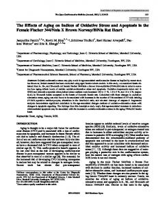
Second, we observe the effect of changing the GOS requirement, which in this case is the mean waiting time W . For stringent W values, such as 0.001 sec, the dial-up architecture always does better. Even at 0.01 and 0.1 sec, the dialup architecture does better and offers positive capacity gains. However, at very lax GOS values, such as a mean waiting time of 1 sec, it appears that even with a small number of end hosts sharing resources, gains can be realized. At this point, the effect of choosing much larger holding times for the dialup calls than in the leased-line architecture results in the leased-line architecture requiring less capacity than the dialup architecture as shown in Fig. 8. We used this lax GOS value to demonstrate the dependence of the capacity gains offered by the dial-up architecture over the leased-line architecture on the relative holding times of calls, the GOS requirement, and the number of hosts sharing resources.
REFERENCES [1]
[2] [3] [4] [5]
[6]
[7]
[8]
Dial-up BCQ W = 1 sec 20 0 -20 0
[9] 200
400
600
800
-40
! = 0.1
-60
! = 0.5
-80
! = 0.9
[10]
-100 -120
[11]
-140 Number of end-hosts
[12] [13]
Fig. 8
Capacity gains using dial-up on the link between the LLSP switch and ISP RAS in the BCQ model with W = 1 sec V. SUMMARY AND CONCLUSIONS
Circuit-switched optical-link and wavelength-routed networks are already being deployed in access configurations for large enterprise buildings. These networks are being used in only a simple leased-line architecture, where voice T1s, data T1s and ethernet links are multiplexed on to a leased optical circuit. We propose adding a switched mode of operation (i.e., adding signaling protocols to the circuit switches) and offering a dial-up service. This service would allow an end host to request and obtain a high-speed circuit to its ISP’s remote access server for Internet access. It would enable a significant increase in the data rate on the weakest link in the current Internet, i.e., wide-area network access links. With analytical comparisons, we showed the capacity savings possible through the use of dial-up access for high-speed circuits. For example, capacity savings of 36% are obtained at 50% traffic load for a mean call waiting time of 1ms with a total of 180 hosts sharing the link even when the dial-up calls have a holding time that is 100000 times the holding time of “calls” in the leased-line architecture.
6
M. Veeraraghavan, M. Karol, R. Karri, R. Grobler, T. Moors, “Architectures and protocols that enable new applications on optical networks,” IEEE Communications Magazine, March 2001, pp. 118-127. B. Mukherjee, Optical Communication Networks, McGraw Hill, 1997. R. Ramaswami and K. N. Sivarajan, Optical Networks: A Practical Perspective, Morgan Kaufmann, 1998. T. Stern, Multiwavelength Optical Networks: A Layered Approach, Addison-Wesley, 1999. J. Bannister, M. Gerla, M. Kovacevic, “Routing in Optical Networks,” Chapter 7 of Routing in Communication Networks, edited by M. Steenstrup, Prentice Hall, 1995. Cisco, “Cisco ONS 15454 Optical Transport Platform,” http:// www.cisco.com/warp/public/cc/pd/olpl/metro/on15454/prodlit/ ons15_ds.htm. D. Awduche, Y. Rekhter, J. Drake, R. Coltun, “Multi-Protocol Lambda Switching: Combining MPLS Traffic Engineering Control With Optical Crossconnects,” draft-awduche-mpls-te-optical-02.txt, July 2000. A. Copley, “Optical Domain Service Interconnect (ODSI): Defining Mechanisms for Enabling On-Demand High-Speed from the Optical Domain,” IEEE Communications Magazine, vol. 38, no. 10, Oct. 2000, pp. 168-174. D. Pendarikis, B. Rajagopalan, D. Saha, “Routing Information Exchange over the UNI and NNI,” Proc. of the Optical Internetworking Forum (OIF) Conference, OIF2000.083, April 2000. W. Whitt, “Blocking when service is required from several facilities simultaneously,” AT&T Bell System Technical Journal. (64), 18071856, 1985. F. Kelly, “Blocking probabilities in large circuit-switched networks,” Advances in Applied Probability, (18), 473-505, 1986. J. Holtzman, “Analysis of dependence effects in telephone trunking networks,” Bell System Technical Journal (5), 2647-2662, 1971. H. Akimaru and K. Kawashima, Teletraffic. Theory and Applications. Springer Verlag, 1993.