SPRAAX9. Using DSP/BIOS in C2800 Applications with High Interrupt Rates. 5 ... background functions that are best handled by a real-time operating system.
Application Report SPRAAX9 –August 2008
Using DSP/BIOS in C2800 Applications with High Interrupt Rates Nick Lethaby and Shreyas Prasad
Texas Instruments, Santa Barbara
ABSTRACT This document presents an overview and comparison of interrupt handling techniques under DSP/BIOS 5.32.03 using the Texas Instruments C2800 DSC (Digital Signal Controller). The application note also presents an analysis of the overhead involved in processing interrupts both inside and outside the DSP/BIOS kernel, including detailed benchmark data. A framework C application included in this document demonstrates extracting benchmark data for the different interrupt handling techniques.
1 2
3
4
5 6 7 8
Contents Overview ..........................................................................................................................................2 Understanding Interrupt Processing Times When Using DSP/BIOS .........................................2 2.1 Terminology ...................................................................................................................2 2.2 Processing an Interrupt in DSP/BIOS............................................................................3 2.2.1 Processing the Interrupt Entirely in a Non-DSP/BIOS ISR ............................................3 2.2.2 Processing an Interrupt in a HWI Using the Interrupt Dispatcher ..................................4 2.2.3 Processing an Interrupt in a SWI ...................................................................................4 2.2.4 Processing an Interrupt in a TSK...................................................................................5 Optimizing High-frequency Interrupts Outside of the DSP/BIOS Kernel ...................................5 3.1 DSP/BIOS Interrupt Dispatcher Features that Reduce Overhead.................................5 3.1.1 Calling Arbitrary C Functions .........................................................................................6 3.1.2 Making DSP/BIOS System Calls ...................................................................................6 3.1.3 Nested Interrupts ...........................................................................................................6 3.2 Performance Tradeoffs ..................................................................................................6 DSP/BIOS C28x Benchmark Framework Application ..................................................................7 4.1 Configuring interrupts.c for Different Interrupt Handling Methods .................................8 4.1.1 Non-DSP/BIOS ISR Configuration.................................................................................8 4.1.2 HWI/Dispatcher Configuration .......................................................................................9 4.1.3 SWI Configuration .........................................................................................................9 4.1.4 TSK Configuration .......................................................................................................10 4.2 Example Source (interrupts.c) .....................................................................................11 Processor Load Results for Interrupts at Various Frequencies ...............................................15 5.1 Example: Processor Load with Fixed Parameters.......................................................15 5.2 Benchmark Program Output ........................................................................................16 Hybrid Method of Processing High-frequency Interrupts .........................................................16 6.1 Hybrid Interrupt Processing Skeleton Code.................................................................18 Conclusion.....................................................................................................................................19 References .....................................................................................................................................19
1
SPRAAX9
1 Overview DSP/BIOS is a real-time operating system (RTOS) that has been successfully deployed in thousands of embedded and real-time applications. A key function of real-time operating systems is interrupt handling. DSP/BIOS simplifies this by enabling interrupt handlers to be written in C and by automatically performing device-specific functions such as context saves and restores. While the overhead of handling interrupts is not significant for many applications such as video decoding, some applications have much higher interrupt rates. In addition, in applications such as motor control, failure to respond in a timely manner to critical interrupts may result in equipment damage or failure. When implementing applications of this nature, developers need to understand the impact of processing an interrupt using the various threading mechanisms available in a RTOS. This application note explains the overhead involved in processing interrupts in DSP/BIOS along with savings you can gain by taking an interrupt outside the kernel. Specific data from DSP/BIOS 5.32.03 on the C2800 is used. An example application using the C2800 architecture is also provided.
2 Understanding Interrupt Processing Times When Using DSP/BIOS For most applications, the recommended method of handling interrupts is to do a minimal amount of processing in a hardware interrupt and defer remaining processing to another thread such as a software interrupt (SWI) or a DSP/BIOS task (TSK). Since hardware interrupts often require that all interrupts are disabled, the advantage of this approach is that interrupts are quickly re-enabled once processing is handed off to the software interrupt or the task. However, as interrupt rates increase, developers need to consider the overhead of the different DSP/BIOS options for interrupt processing, or whether they can even handle an interrupt in DSP/BIOS. The following subsections define terminology, give an overview of the DSP/BIOS interrupt dispatcher, and provide a detailed breakdown of overhead for each of the ways that DSP/BIOS can handle an interrupt. For additional information, refer to the DSP/BIOS Benchmarks guide (SPRAA16).
2.1
Terminology Since terms like “interrupt latency” mean different things to different people, we will first define some terms as they are used in this application note. We’ll also review the different DSP/BIOS thread types. Please refer to the DSP/BIOS Users Guide (SPRU423) for a more detailed description of different types of DSP/BIOS threads.
2
•
OS interrupt latency. The maximum time that DSP/BIOS disables interrupts while accessing critical OS data structures. The kernel disables interrupts relatively infrequently and most interrupts will not incur this latency. However, developers must always factor in this interrupt latency to understand the worst-case scenario. Control engineers should consider that OS interrupt latency adds directly to control loop delay, increasing the amount of phase lag present in a closed loop system.
•
Interrupt processing time. The round-trip time spent in the kernel from the time an interrupt is asserted, until the processing response is completed. Note that this does not include the time spent in the application code to handle the specifics of interrupt servicing.
Using DSP/BIOS in C2800 Applications with High Interrupt Rates
SPRAAX9
2.2
•
Interrupt Service Routine (ISR). A non-DSP/BIOS function or assembly code routine used to handle an interrupt from a hardware peripheral outside of the DSP/BIOS kernel.
•
Hardware Interrupt (HWI). A DSP/BIOS thread used to respond to an interrupt from a hardware peripheral. A HWI is the DSP/BIOS equivalent of an ISR and has inherently higher priority than a SWI or TSK.
•
Software Interrupt (SWI). A DSP/BIOS thread that is preemptible based on its priority, but cannot yield the processor. All SWIs are inherently higher priority than any TSK.
•
Task (TSK). A DSP/BIOS thread that is preemptible based on its priority, but can yield the processor, for example by pending on semaphores or message queues.
•
Interrupt-to-SWI time. The elapsed time between an interrupt being triggered and the first instruction in the highest-priority posted SWI. When using a DSP/BIOS HWI, the interrupt is triggered at the point where processing enters the HWI dispatcher.
•
Interrupt-to-TSK time. The elapsed time between an interrupt being triggered and the first instruction in the highest-priority ready TSK.
Processing an Interrupt in DSP/BIOS This section describes four methods of processing interrupts. The first two methods process an interrupt entirely in a non-DSP/BIOS ISR or in a HWI. The second two use a HWI that defers most of the processing to either a SWI or a TSK.
2.2.1 Processing the Interrupt Entirely in a Non-DSP/BIOS ISR If an ISR does not directly post a SWI or TSK or modify a data structure also accessed by a SWI or TSK, then it probably makes sense to handle the interrupt outside of the kernel. The TI C compiler provides an “interrupt” keyword that allows non-DSP/BIOS ISRs to be written as C functions. In order to process an interrupt, the register context needs to be saved. An non-DSP/BIOS ISR with the interrupt keyword is “sandwiched” implicitly by the compiler with an additional set of assembly instructions at compile time, that saves and restores registers modified by the ISR. When an interrupt is asserted by the hardware, the application enters the sandwiched nonDSP/BIOS ISR, which saves the register context and processes the interrupt. Once the instructions corresponding to the user code are complete, the non-DSP/BIOS ISR restores the context to complete the interrupt processing. Processing an interrupt entirely outside of DSP/BIOS reduces the need to consider thread preemption in calculating worst-case processing times. In addition, a non-DSP/BIOS ISR will often handle interrupts faster than the standard DSP/BIOS interrupt dispatcher. (See Section 3 for a more detailed discussion of code size and performance tradeoffs.) There are several potential disadvantages to this approach, however. First, it is not possible for a non-DSP/BIOS ISR to directly make DSP/BIOS system calls. Therefore, if it is necessary for the ISR to interact with background tasks, an indirect mechanism is required (see Section 6) or interrupts may need to be disabled for longer periods to protect data structures later accessed by SWIs or TSKs. Further, in applications that have several interrupt sources, multiple nonDSP/BIOS ISRs consume more code space than the DSP/BIOS interrupt dispatcher. (For more information about optimizing interrupts outside the DSP/BIOS kernel, see Section 3.)
Using DSP/BIOS in C2800 Applications with High Interrupt Rates
3
SPRAAX9
2.2.2 Processing an Interrupt in a HWI Using the Interrupt Dispatcher Unlike a non-DSP/BIOS ISR that uses the interrupt keyword, a HWI uses a separate DSP/BIOS routine called the “dispatcher” to perform register save operations before dispatching a userspecified C or assembly function as an interrupt handler. Although the performance overhead of the dispatcher is often greater than that of a non-DSP/BIOS ISR, using the dispatcher enables the HWI function to call any DSP/BIOS system routine and modify variables that are also accessed by background threads like TSKs or SWIs. This approach processes an interrupt without entering the core multithreading kernel. As a result, developers do not need to consider potential preemption by other threads, as may happen if an interrupt is eventually processed by a TSK or SWI. Table 1 compares characteristics of HWIs with non-DSP/BIOS ISRs. Table 1. Feature
Comparison of Non-DSP/BIOS ISRs and HWIs Non-DSP/BIOS ISR
HWI
Context Save/Restore
Only modified registers are saved/restored.
All scratch registers are saved/restored.
Hardware Interrupts
All hardware interrupts disabled during ISR.
By default, dispatcher re-enables all interrupts except the one being handled.
Code Size
Higher for multiple ISRs.
Lower for multiple ISRs.
Processor Overhead
Usually lower.
Higher.
When an interrupt is asserted by the hardware, the DSP/BIOS interrupt dispatcher is entered. The interrupt dispatcher first saves the register context and disables kernel pre-emption. It then updates the interrupt mask (to disable the interrupt it is currently processing) before re-enabling interrupts, which allows handling of nested interrupts. Next, it calls the HWI function that will process the interrupt. Once the HWI function is completed, the HWI dispatcher is entered again, SWI and TSK pre-emption are enabled and the context is restored to complete the interrupt processing. For a more detailed discussion of DSP/BIOS interrupt dispatcher operations, see Section 3.
2.2.3 Processing an Interrupt in a SWI This approach defers processing the interrupt to a SWI. A SWI must always first be posted by a HWI to process an interrupt. Any references to “processing an interrupt in a SWI” in this document refer to a combination of a HWI and a SWI. A SWI provides faster deferred interrupt processing than a TSK. A significant advantage compared to the HWI-only approach is that there is no requirement to disable interrupts during the SWI. This may significantly reduce the period for which interrupts need to be disabled. When an interrupt is asserted by the hardware, the DSP/BIOS interrupt dispatcher is entered and it calls the HWI function. In this case, the HWI function consists simply of a SWI_post function. Once the HWI function returns, the kernel is entered and the DSP/BIOS scheduler is run. If there is no other higher-priority SWI running, the posted SWI function runs. Note that this SWI function can be pre-empted at any point by a HWI or higher-priority SWI, so the most timecritical interrupts should be the highest priority SWIs. When the SWI function completes, execution returns to the HWI dispatcher to complete interrupt processing.
4
Using DSP/BIOS in C2800 Applications with High Interrupt Rates
SPRAAX9
2.2.4 Processing an Interrupt in a TSK This approach has the greatest kernel overhead, but is sometimes preferred by developers who are familiar with tasks from this or other real-time operating systems, or who want to use threads that can yield the processor. Like SWIs, the overhead in this scenario includes both a TSK and the HWI that posts it. An advantage over the HWI-only approach is that there is no requirement to disable interrupts during the TSK. This significantly reduces the period during which interrupts need to be disabled. When an interrupt is asserted by the hardware, the DSP/BIOS interrupt dispatcher is entered and it calls the HWI function. The HWI function consists simply of a semaphore post function that defers processing to a TSK. Once the TSK is posted, the kernel is entered and the DSP/BIOS scheduler runs. If no higher-priority TSK is running, the posted TSK will run. To complete the interrupt processing, the TSK pends and execution returns to the HWI dispatcher. Note that this TSK function can be pre-empted at any point by a HWI, SWI, or higher-priority TSK, so the most time-critical interrupts should be the highest priority TSKs. Typically, an application that defers interrupt processing to a TSK would not include any SWIs.
3 Optimizing High-frequency Interrupts Outside of the DSP/BIOS Kernel Some applications have a very high-frequency interrupt and a number of other interrupt-driven background functions that are best handled by a real-time operating system. In such cases, consider handling the high-frequency interrupt outside of DSP/BIOS in a non-DSP/BIOS ISR. This eliminates any dispatcher and kernel overhead with the exception of the OS interrupt latency, which will only occasionally be incurred. The drawback to this approach is that the non-DSP/BIOS ISR cannot interact with the kernel. Typically it will buffer up any information required to be passed into the kernel-based part of the application. A less-frequent interrupt may be used to pass this data in a thread-safe manner to the kernel-based application. For more about passing data between a non-DSP/BIOS interrupt and the kernel, please see Section 6.
3.1
DSP/BIOS Interrupt Dispatcher Features that Reduce Overhead To understand how much overhead may be reduced by using a non-DSP/BIOS ISR, it is essential to understand what operations are performed by the DSP/BIOS interrupt dispatcher and why they are needed. The following sections summarize the features offered by the dispatcher, the operations required to implement them, and how a non-DSP/BIOS ISR can be optimized to provide faster performance.
Using DSP/BIOS in C2800 Applications with High Interrupt Rates
5
SPRAAX9
3.1.1 Calling Arbitrary C Functions The interrupt dispatcher not only enables you to write a HWI function in C, but also lets you call any C function from within the HWI function, including DSP/BIOS system calls. As a result, the dispatcher must save and restore the entire scratch (save-on-call) register context required by arbitrary C programs. If the interrupt is handled by a non-DSP/BIOS ISR that does not interact directly with DSP/BIOS or call any additional C functions, the context save/restore for the scratch (save-on-call) registers can be optimized to only those registers modified by the ISR. If the “interrupt” keyword is used for the non-DSP/BIOS ISR function, the compiler will automatically optimize the context/save restore to those registers used in the ISR (provided that no external C functions are called). Alternatively, the developer can hand-optimize the save/restore operations in assembly code.
3.1.2 Making DSP/BIOS System Calls HWIs typically interact with the DSP/BIOS kernel by making a DSP/BIOS system call such as a SEM_post or SWI_post. To ensure that the HWI function can complete and exit before any context switch to a SWI or TSK is made, the dispatcher must disable SWI and TSK pre-emption before calling the HWI function. Once the HWI function returns, it re-enables SWI and TSK preemption and the application will context switch to the highest priority thread that is able to run. Since a non-DSP/BIOS ISR cannot make DSP/BIOS system calls, it need not do any disable/enable kernel pre-emption operations.
3.1.3 Nested Interrupts By default, the processor hardware disables all interrupts when an interrupt is asserted. Since the dispatcher supports nested interrupts, it updates the interrupt mask and then re-enables interrupts prior to calling the HWI function. The interrupt mask is user-defined. The default setting only disables the interrupt that is currently being handled. If nested interrupts are not required by the application, a non-DSP/BIOS ISR can simply leave interrupts disabled while executing.
3.2
Performance Tradeoffs The features described in Section 3.1 and its subsections explain how a simple non-DSP/BIOS ISR can have significantly less overhead. However, non-DSP/BIOS ISRs that call external C functions and support interrupt nesting offer only marginal performance gains compared to the DSP/BIOS dispatcher. It should also be noted that using non-DSP/BIOS ISRs increases code size in a system with multiple interrupts. The DSP/BIOS dispatcher centralizes all context save/restore code in one place. In contrast, the non-DSP/BIOS ISRs require the context save/restore code to be added into each ISR, so it is duplicated for every ISR in the system. Even allowing for the fact that context save/restore is often optimized for each non-DSP/BIOS ISR, in systems with three or more interrupts, there would typically be a code size increase compared to using the dispatcher.
6
Using DSP/BIOS in C2800 Applications with High Interrupt Rates
SPRAAX9
4
DSP/BIOS C28x Benchmark Framework Application This section demonstrates benchmarking of high-frequency interrupts under DSP/BIOS 5.32.035 on the C2800 ISA, using provided sample code. A CCStudio 3.3 project is supplied with C code that you can modify and build to benchmark all four interrupt handling scenarios (non-DSP/BIOS ISR, HWI, SWI, and TSK) described in the previous sections. The supplied source code (interrupts.c) is designed to be easily modified to implement each of the four scenarios. Table 2 provides a list of breakpoints used to acquire benchmark data using the built-in profiler in CCStudio 3.3. Once the code has been modified to implement a specific scenario, you may place breakpoints at the specified C and assembly locations in order to sample the number of cycles required for each stage. The interrupts.c source code is provided in Section 4.2. Table 2.
Breakpoints Used to Benchmark interrupts.c
Breakpoint Name myISR_start
Breakpoint Location (ASM) First instruction after myISR:
Notes Used exclusively to benchmark interrupts using “interrupt” keyword.
myISR_end
(ASM) IRET in myISR
Only used to test cycles needed for “interrupt” keyword.
HWI_dispatch_start
(ASM) First instruction after HWI_F_dispatch:
008007 E200 MOV32 *SP++, STF
HWI_dispatch_end
(ASM) Last instruction in HWI_F_dispatch- IRET
0080A9 7602 IRET (Final instruction in interrupt handling routine.)
myHWI_start
(C) First statement in myHWI
HWI_dispatch_ep
(ASM) At location to the right
008091 8D00 MOVL XAR0,#0x00CE87
SEM_post
(C) SEM_post in myHWI
Used exclusively to benchmark interrupt handling using TSKs.
SEM_pend
(C) SEM_pend in myTSK
Used exclusively to benchmark interrupt handling using TSKs.
SWI_post
(C) SWI_post in mySWI
Used exclusively to benchmark interrupt handling using SWIs.
The subsections that follow provide a detailed overview of the kernel overhead for each of the previously described interrupt handing methods. The cycle counts given are specific to version 5.32.035 of DSP/BIOS running on a TMS320F2812 DSP, and version 5.0.2 of the C2000 code generation tools. For each scenario, a diagram is given, along with the DSP/BIOS benchmark entries that are needed to calculate them. This enables you to easily calculate similar results for any other ISA or DSP/BIOS release version. The DSP/BIOS product release notes contain links to the timing benchmarks for a specific release. Each illustration of kernel overhead, including one for a non-DSP/BIOS ISR, begins with a worstcase OS interrupt latency period. Although worst-case OS interrupt latency is rarely experienced by the application, a developer must factor it into any interrupt processing time calculation, whether the interrupt is handled by the OS or not. It is important to understand the potential for OS interrupt latency to delay interrupt recognition and to determine whether the amount of OS interrupt latency is acceptable for the application. Although the OS interrupt latency for DSP/BIOS is relatively short and acceptable for the great majority of general applications, many C2800 applications, for example power control, have very limited tolerance for such latency.
Using DSP/BIOS in C2800 Applications with High Interrupt Rates
7
SPRAAX9 Benchmarks for each interrupt handling method discussed in previous sections are comprised of a set of stages, illustrated in Table 3. Each stage contains: •
A stage identifier.
•
The specific measurement to use from the DSP/BIOS timing benchmarks to reconstruct the measurement for a specific version of DSP/BIOS on a specific architecture.
•
The start and end breakpoints used to profile the stage. (For a list of breakpoints to use for profiling the provided example file, see Table 2.)
•
The number of cycles needed to complete the stage.
Table 3 shows how the data is presented for a single ISR stage. Table 3.
An ISR Stage
Stage name
Profile end point
Profile start point
DSP/BIOS Benchmark Table entry to use
Number of Cycles
4.1
Configuring interrupts.c for Different Interrupt Handling Methods The subsections that follow describe how to configure the file interrupts.c in the provided sample code to use one of the four interrupt-handling methods to evaluate processor overhead. Tables summarize the breakpoint locations to use for each method and the cycles consumed. See Table 3 to understand the layout of the tables in the following subsections.
4.1.1 Non-DSP/BIOS ISR Configuration In this scenario, interrupt processing is performed in a function with the “interrupt” keyword, called myISR(). The interrupt corresponding to the hardware timer (interrupt 13) is configured to be handled by myISR(). This is the only interrupt handling method that does not call the dispatcher. Instead, C code in the ISR is “sandwiched” by additional instructions to perform register save and restore operations. Set “#define INTR_MODE” to “ISR_MODE” to run this scenario. Table 4 shows the interrupt latency, breakpoint locations and processing time in cycles.
8
Using DSP/BIOS in C2800 Applications with High Interrupt Rates
SPRAAX9 Table 4.
Interrupt Processing Time for Non-DSP/BIOS ISR {USER DEFINED HWI FUNCTION – No dispatcher}
Interrupt Latency
(Not Applicable)
88
myISR_end
myISR_start
Worst Case Interrupt Latency
16 (Lower bound)
4.1.2 HWI/Dispatcher Configuration In this scenario, myHWI() is a hardware interrupt routine that is periodically triggered within myISR to handle the timer interrupt. Unlike myISR(), myHWI() register save operations are handled by the interrupt dispatcher. Set “#define INTR_MODE” to “HWI_MODE” to run this scenario. The latency overhead, breakpoint locations and processing time are shown in Table 5. Table 5.
Interrupt Processing Time for DSP/BIOS HWI (Using Dispatcher) HWI Dispatcher Epilogue
Interrupt Latency
HWI_dispatch: Interrupt prolog for calling C function
HWI_dispatch: Interrupt epilog following C function call
88
107
HWI_dispatch_ep
myHWI_start
{USER-DEFINED HWI FUNCTION}
HWI_dispatch_end
HWI Dispatcher Prologue
HWI_dispatch_start
Worst Case Interrupt Latency
110
4.1.3 SWI Configuration In this scenario, myHWI() calls SWI_post() to invoke a software interrupt routine called mySWI(). It is important to note that, when using SWIs and TSKs, the total interrupt processing time is permitted to exceed the periodicity of the interrupt timer that calls myHWI to highlight the value of processing interrupts within DSP/BIOS. To process interrupts in SWIs, set “#define INTR_MODE” to “SWI_MODE”.
Using DSP/BIOS in C2800 Applications with High Interrupt Rates
9
SPRAAX9 Table 6 shows the worst case interrupt latency, breakpoint locations and processing time in cycles for the HWI and SWI stages necessary to process an interrupt in a SWI.
HWI_dispatch: Interrupt epilog following C function call
88
SWI_post
(SWI Scheduler)
Interrupt-to-SWI time HWI_dispatch_start
Interrupt Latency
HWI Dispatcher Epilogue
SWI Post
HWI_dispatch_end
HWI Dispatcher Prologue
myHWI_start
Worst Case Interrupt Latency
Interrupt Processing Time for DSP/BIOS SWI
HWI_dispatch_ep
Table 6.
{USER DEFINED SWI FUNCTION}
Å 355 Æ
110
4.1.4 TSK Configuration Similar to the scenario involving SWIs, we can choose to perform additional processing in a Task. myTSK() is invoked when a semaphore is posted in myHWI(). To enable this scenario, set “#define INTR_MODE” to “TSK_MODE”. Table 7 shows the interrupt latency, breakpoints and processing cycles for the stages of the HWI dispatcher and TSK.
88 #
10
Å 938 Æ
Posting/pending semaphore includes context switch
Using DSP/BIOS in C2800 Applications with High Interrupt Rates
342
HWI_dispatch: Interrupt epilog following C function call
HWI_dispatch_end
(Task Scheduler)
SEM_post
{USER DEFINED TSK FUNCTION}
HWI Dispatcher Epilogue
HWI_dispatch_ep
SEM_pend: Pend on a semphore, context switch
Interrupt-to-TSK time HWI_dispatch_start
Interrupt Latency
SEM Pend #
SEM Post #
(Task Scheduler)
HWI Dispatcher Prologue
myHWI_start
Worst Case Interrupt Latency
Interrupt Processing Time for DSP/BIOS TSK
SEM_pend
Table 7.
110
SPRAAX9
4.2
Example Source (interrupts.c) /* * Copyright 2008 by Texas Instruments Incorporated. * All rights reserved. Property of Texas Instruments Incorporated. * Restricted rights to use, duplicate or disclose this code are * granted through contract. */ /* * ======== interrupts.c ======== * Sample code that demonstrates benchmarking high frequency * interrupts under DSP/BIOS on the C2800 ISA */ #include #include #include #include #include #include #include #include #include "DSP281x_Device.h" /* * We enter either myHWI or myISR every 'timerPeriod' microseconds. * timerPeriod decreases periodically by HWIPRD_DELTA between * HWIPRD_MAX and HWIPRD_MIN */ #define TIMERPRD_MAX 100 #define TIMERPRD_MIN 10 #define TIMERPRD_DELTA 10 #define #define #define #define
ISRMODE HWIMODE SWIMODE TSKMODE
1 2 3 4
/* * LOGVERBOSITY < 1: No trace output * LOGVERBOSITY >= 1: Output values of timerPeriod (default) * LOGVERBOSITY >= 2: Output above + debug messages from * myISR, myISR, myISR and myISR */ #define LOGVERBOSITY 1 /* Modify this to set the interrupt mode */ #define INTR_MODE TSKMODE float32 freq; /* Processor frequency */ extern LOG_Obj trace; struct CPUTIMER_VARS CpuTimer1; #if INTR_MODE == TSKMODE TSK_Handle tsk0; SEM_Handle sem0; #elif INTR_MODE == SWIMODE SWI_Handle swi0; #endif Uint16 timerPeriod; Uint32 count;
Using DSP/BIOS in C2800 Applications with High Interrupt Rates
11
SPRAAX9 /* * ======== decTimerPrd ======== * PRD function that changes timer interrupt period every 10 seconds */ Void decTimerPrd(Void) { timerPeriod -= TIMERPRD_DELTA; if (timerPeriod < TIMERPRD_MIN) { timerPeriod = TIMERPRD_MAX; } CpuTimer1.PeriodInUSec = (float)timerPeriod; CpuTimer1.RegsAddr = &CpuTimer1Regs; CpuTimer1.RegsAddr->PRD.all = (Uint32) (freq * (float32)timerPeriod); ReloadCpuTimer1(); #if LOGVERBOSITY >= 1 LOG_printf(&trace,"Timer period is now %d",timerPeriod); #endif } /* * ======== myISR ======== * Non-DSP/BIOS ISR */ #if INTR_MODE == ISRMODE interrupt void myISR(void) { #if LOGVERBOSITY >= 2 LOG_printf(&trace, "myISR entered, count = 0x%04x%04x", (Uint16)(count >> 16),(Uint16)(count & 0xffff)); #endif count++; } #endif /* * ======== myHWI ======== * HWI (using dispatcher) */ #if INTR_MODE >= HWIMODE void myHWI(void) { #if LOGVERBOSITY >= 2 LOG_printf(&trace, "myHWI entered, count = 0x%04x%04x", (Uint16)(count >> 16),(Uint16)(count & 0xffff)); #endif count++; /* Post to either the TSK or SWI */ #if INTR_MODE == TSKMODE SEM_post(sem0); #elif INTR_MODE == SWIMODE SWI_post(swi0); #endif /* ACK the interrupt */ PieCtrlRegs.PIEACK.bit.ACK11 = 1; } #endif
12
Using DSP/BIOS in C2800 Applications with High Interrupt Rates
SPRAAX9 /* * ======== myTSK ======== * TSK entered by posting to sem0 */ #if INTR_MODE == TSKMODE Void myTSK() { while (1) { SEM_pend(sem0, SYS_FOREVER); #if LOGVERBOSITY >= 2 LOG_printf(&trace,"myTSK entered"); #endif } } #endif /* * ======== mySWI ======== * SWI routine entered by posting to swi0 */ #if INTR_MODE == SWIMODE Void mySWI() { #if LOGVERBOSITY >= 2 LOG_printf(&trace,"mySWI entered"); #endif } #endif /* * ======== ConfigCpuTimer ======== * Initializes the registers associated with a given timer */ void ConfigCpuTimer ( struct CPUTIMER_VARS *Timer, float32 myFreq, float32 Period) { Uint32 temp; Timer->RegsAddr = &CpuTimer1Regs; /*--- Initialize timer period: ---*/ Timer->CPUFreqInMHz = myFreq; Timer->PeriodInUSec = Period; temp = (Uint32) (myFreq * Period); Timer->RegsAddr->PRD.all = temp; /* Set pre-scale counter to divide by 1 (SYSCLKOUT): */ Timer->RegsAddr->TPR.all = 0; Timer->RegsAddr->TPRH.all = 0;
Using DSP/BIOS in C2800 Applications with High Interrupt Rates
13
SPRAAX9 /*--- Initialize timer control register: (TCR) ----*/ /* 1 = Stop timer, 0 = Start/Restart Timer */ Timer->RegsAddr->TCR.bit.TSS = 1; /* 1 = reload timer */ Timer->RegsAddr->TCR.bit.TRB = 1; Timer->RegsAddr->TCR.bit.SOFT = 0; /* Timer Free Run Disabled */ Timer->RegsAddr->TCR.bit.FREE = 0; /* 0 = Disable/ 1 = Enable Timer Interrupt */ Timer->RegsAddr->TCR.bit.TIE = 1; /* Reset interrupt counter: */ Timer->InterruptCount = 0; } /* * ======== main ======== */ Void main(Void) { #if INTR_MODE == SWIMODE SWI_Attrs swiattrs = SWI_ATTRS; #elif INTR_MODE == TSKMODE TSK_Attrs tskattrs = TSK_ATTRS; #endif #if INTR_MODE == ISRMODE LOG_printf(&trace, "ISR #elif INTR_MODE == HWIMODE LOG_printf(&trace, "HWI #elif INTR_MODE == SWIMODE LOG_printf(&trace, "SWI #else LOG_printf(&trace, "TSK #endif
Mode"); Mode"); Mode"); Mode");
/* Set initial values for benchmark variables */ count = 0; #if INTR_MODE == ISRMODE /* Plug the PIE table with myISR */ EALLOW; PieVectTable.XINT13 = &myISR; EDIS; #else /* Plug the dispatcher with myHWI */ HWI_dispatchPlug(13, (Fxn)myHWI, NULL); #endif #if INTR_MODE == TSKMODE /* Create a semaphore the task pends on */ sem0 = SEM_create(0,NULL); if (sem0 == NULL) { SYS_abort("Semaphore creation failed!"); } tskattrs.priority = TSK_MAXPRI; tsk0 = TSK_create((Fxn)myTSK, &tskattrs); if (tsk0 == NULL) { SYS_abort("TSK creation failed!"); }
14
Using DSP/BIOS in C2800 Applications with High Interrupt Rates
SPRAAX9 #elif INTR_MODE == SWIMODE /* Create a swi used with mySwi() */ swiattrs.fxn = (SWI_Fxn)&mySWI; swi0 = SWI_create(&swiattrs); if (swi0 == NULL) { SYS_abort("SWI creation failed!"); } #endif /* Config timer */ timerPeriod = TIMERPRD_MAX; #if LOGVERBOSITY >= 1 LOG_printf(&trace, "Starting timer with period %d", timerPeriod); #endif freq = (float32)(GBL_getFrequency() / 1000); ConfigCpuTimer(&CpuTimer1, freq, (float)timerPeriod); CpuTimer1Regs.TCR.all = 0x4001; /* Enable interrupt 13 (timer 1) */ C28_enableIER(M_INT13); }
5 Processor Load Results for Interrupts at Various Frequencies In this section, we demonstrate how to measure CPU load due to overhead caused by high frequency interrupts. Familiarity with interrupts.c and material discussed in Section 4 is recommended. We can modify preprocessor directives in order to benchmark interrupts.c under varying conditions. The following is a description of parameters (#define statements at the top of interrupts.c) and the effects they have on the behavior of the software.
5.1
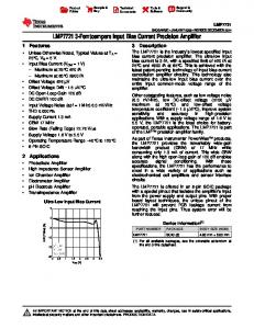
Example: Processor Load with Fixed Parameters The “timerPeriod” is a C variable whose value is the periodicity of the timer interrupt in microseconds. This value is varied periodically every N milliseconds (where N is set to 10,000 by default in interrupts.tcf) so that we may observe in real time the relationship between timer interrupt frequency and load (% CPU usage) due to overhead as shown in Figure 1. “timerPeriod” is initialized to TIMERPRD_MAX and it is decreased by TIMERPRD_DELTA until its value reaches TIMERPRD_MIN. At that point, timerPeriod is reset to TIMERPRD_MAX. The default values for these parameters are shown in Table 8. Table 8.
Default Benchmark Parameters
Parameter TIMERPRD_MAX
Default Fixed Value 100
TIMERPRD_MIN
10
TIMERPRD_DELTA INTR_MODE
10 ISR_MODE
Using DSP/BIOS in C2800 Applications with High Interrupt Rates
15
SPRAAX9 Figure 1.
Processor Load (%) versus timerPeriod (μs) for Different Interrupt Processing Methods 100%
ISR
90%
HWI
SWI
TSK
80% 70% Processor Load
60% 50% 40% 30% 20% 10% 0% 100
90
80
70
60
50
40
30
20
10
timerPeriod (μs)
5.2
Benchmark Program Output The interrupts.c program offers multiple levels of logging verbosity. By default, log trace output is restricted to messages containing the newly changed value of “timerPeriod”. We can determine the number of times we have entered each of the interrupt handling routines by outputting the value of “count” when we enter myISR or myHWI, as shown in the following box. In order to enable this output, set the LOG_VERBOSITY preprocessor variable in interrupts.c to a value greater than or equal to 2. myHWI entered, count = 0x0048a5e8 myTSK entered
6 Hybrid Method of Processing High-frequency Interrupts Sometimes a high frequency interrupt must interact with the operating system, such as when low-priority processing is performed in the kernel on data that arrives frequently. In the previous benchmarks, we saw that the cost of handling interrupts using DSP/BIOS is variably greater than handling interrupts outside the kernel. In some cases, the minimum amount of time required to process an interrupt using one of the DSP/BIOS mechanisms might be only slightly less than the time available. In such a scenario, we can move lower-priority processing from a non-DSP/BIOS ISR to the kernel via a HWI that we trigger infrequently compared to the ISR. An example of this might be a console application that displays some statistics on motor control performance. The high-frequency motor control interrupt is handled outside of DSP/BIOS to minimize overhead, but at some point it will need to pass some data into the application running on the operating system. One technique to achieve this is summarized in the following steps and shown in Figure 2:
16
Using DSP/BIOS in C2800 Applications with High Interrupt Rates
SPRAAX9 1.
The motor control ISR buffers data samples needed for the console statistical display.
2.
Each time 128 samples are acquired, the ISR triggers another ISR handled by a DSP/BIOS HWI. On the C28x, this is done by writing to the Interrupt Flag Register (IFR).
3.
The HWI function passes the data samples up to the console thread (SWI or TSK). This requires a data copy, since the only other way to avoid the ISR possibly modifying the data sample structure while the TSK or SWI is accessing would be to disable interrupts.
4.
The SWI or TSK may be preempted by a timer interrupt at any time. In this case, we save the new samples in a different buffer from the one being processed by the SWI or TSK. After the ISR terminates, DSP/BIOS regains control of the processor and the SWI/TSK continues processing.
This approach keeps the motor control ISR very efficient since it just needs to perform an “ifcheck” and increment a count for 127 out of 128 executions. Only on the 128th interrupt does it trigger the DSP/BIOS HWI.
Figure 2.
Hybrid Interrupt Processing
Interrupt Received
SWI/TSK Preempted
SWI/TSK Preempted
Non-DSP/BIOS ISR (Add samples to Buffer)
No
Buffer Full?
No
Yes
Buffer left to process?
HWI
Yes
SWI/TSK (data copy & start processing new buffer)
SWI/TSK (continue processing existing buffer)
Buffer processing complete
Wait for next interrupt
Using DSP/BIOS in C2800 Applications with High Interrupt Rates
17
SPRAAX9
6.1
Hybrid Interrupt Processing Skeleton Code The skeleton code that follows demonstrates hybrid interrupt processing, the technique of infrequently deferring interrupt processing to the DSP/BIOS kernel. In this demonstration, we handle the timer interrupt (interrupt 13) in myISR() as usual. However, after every HWIPRD invocations of myISR(), we trigger another interrupt that is handled by myHWI(). The peripheral interrupt expansion (PIE) vector table entry corresponding to INT11.1 (PIE group 11, interrupt 1) has been plugged by myHWI() using the HWI_dispatchPlug() DSP/BIOS API call. We chose INT11.1 because this interrupt was not being used by any hardware peripherals. Using the HWI_dispatchPlug() call causes myHWI() to be invoked by the dispatcher whenever interrupt INT11.1 occurs. We can trigger interrupt INT11.1 by manually flagging the appropriate bit in PIE group 11’s interrupt flag register (IFR). For more information about the PIE vector table, please refer to the TMS320x280x, 2801x, 2804x System Control and Interrupts Reference Guide (SPRU712). We invoke INT11.1 every HWIPRD invocations of myISR(). The value “count” keeps track of the number of times myISR() has been invoked. The value “snapshot” is equal to the value of “count” at the point where the hardware interrupt handled by myHWI() is triggered. If “snapshot” does not equal “count” when myTSK() executes the statements that output the log text, one or more timer interrupts have occurred during the course of the interrupt routine involving myHWI(). In fact, the number of timer interrupts that have occurred during this period is equal to the difference between “snapshot” and “count”. #define HWIPRD 10 Uint32 count, snapshot; interrupt Void myISR(Void) { count++; if ((count % HWIPRD) == 0) { snapshot = count; /* Trigger hardware interrupt 11 */ PieCtrlRegs.PIEIFR11.bit.INTx3 = 1; } return; } Void myHWI(Void) { SEM_post(mySem); PieCtrlRegs.PIEACK.bit.ACK11 = 1; }
/* Post to the TSK */ /* ACK the interrupt */
Void myTSK() { Uint16 difference; while (1) { difference = (Uint16)(snapshot & 0xffff) ((Uint16)(count & 0xffff); LOG_printf(&trace,"myTSK() has been preempted %d times", difference); SEM_pend(mySem, SYS_FOREVER); } }
18
Using DSP/BIOS in C2800 Applications with High Interrupt Rates
SPRAAX9
7 Conclusion We have presented several different approaches to processing interrupts in a DSP/BIOS application using the Texas Instruments C2800 DSC. These approaches describe ways to handle interrupts both inside and outside of DSP/BIOS. Detailed benchmarks are given to illustrate the potential overhead involved for each approach, as well as explanations of OS interrupt latency and how the DSP/BIOS interrupt dispatcher works. C2800 application developers should first determine whether their application can tolerate the OS interrupt latency. If this is acceptable, they should then determine the most appropriate interrupt handling technique for each of their system’s interrupts, paying special attention to any high-frequency interrupts. In environments that involve high interrupt frequencies, it may be advantageous to categorize interrupt handling operations into those that can be deferred to a TSK or SWI and those that need to be performed in the ISR/HWI. Once this separation has been made, the optimal interrupt handling technique may be a hybrid technique offering the low interrupt latency of non-DSP/BIOS ISRs with the versatility of DSP/BIOS kernel processing.
8 References •
TMS320 DSP/BIOS User's Guide (SPRU423F)
•
TMS320C28x DSP/BIOS 5.32 Application Programming Interface (API) Reference Guide (SPRU625I)
•
TMS320x280x, 2801x, 2804x DSP System Control and Interrupts Reference Guide (SPRU712F)
•
DSP/BIOS Benchmarks (SPRAA16D)
Using DSP/BIOS in C2800 Applications with High Interrupt Rates
19
IMPORTANT NOTICE Texas Instruments Incorporated and its subsidiaries (TI) reserve the right to make corrections, modifications, enhancements, improvements, and other changes to its products and services at any time and to discontinue any product or service without notice. Customers should obtain the latest relevant information before placing orders and should verify that such information is current and complete. All products are sold subject to TI’s terms and conditions of sale supplied at the time of order acknowledgment. TI warrants performance of its hardware products to the specifications applicable at the time of sale in accordance with TI’s standard warranty. Testing and other quality control techniques are used to the extent TI deems necessary to support this warranty. Except where mandated by government requirements, testing of all parameters of each product is not necessarily performed. TI assumes no liability for applications assistance or customer product design. Customers are responsible for their products and applications using TI components. To minimize the risks associated with customer products and applications, customers should provide adequate design and operating safeguards. TI does not warrant or represent that any license, either express or implied, is granted under any TI patent right, copyright, mask work right, or other TI intellectual property right relating to any combination, machine, or process in which TI products or services are used. Information published by TI regarding third-party products or services does not constitute a license from TI to use such products or services or a warranty or endorsement thereof. Use of such information may require a license from a third party under the patents or other intellectual property of the third party, or a license from TI under the patents or other intellectual property of TI. Reproduction of TI information in TI data books or data sheets is permissible only if reproduction is without alteration and is accompanied by all associated warranties, conditions, limitations, and notices. Reproduction of this information with alteration is an unfair and deceptive business practice. TI is not responsible or liable for such altered documentation. Information of third parties may be subject to additional restrictions. Resale of TI products or services with statements different from or beyond the parameters stated by TI for that product or service voids all express and any implied warranties for the associated TI product or service and is an unfair and deceptive business practice. TI is not responsible or liable for any such statements. TI products are not authorized for use in safety-critical applications (such as life support) where a failure of the TI product would reasonably be expected to cause severe personal injury or death, unless officers of the parties have executed an agreement specifically governing such use. Buyers represent that they have all necessary expertise in the safety and regulatory ramifications of their applications, and acknowledge and agree that they are solely responsible for all legal, regulatory and safety-related requirements concerning their products and any use of TI products in such safety-critical applications, notwithstanding any applications-related information or support that may be provided by TI. Further, Buyers must fully indemnify TI and its representatives against any damages arising out of the use of TI products in such safety-critical applications. TI products are neither designed nor intended for use in military/aerospace applications or environments unless the TI products are specifically designated by TI as military-grade or "enhanced plastic." Only products designated by TI as military-grade meet military specifications. Buyers acknowledge and agree that any such use of TI products which TI has not designated as military-grade is solely at the Buyer's risk, and that they are solely responsible for compliance with all legal and regulatory requirements in connection with such use. TI products are neither designed nor intended for use in automotive applications or environments unless the specific TI products are designated by TI as compliant with ISO/TS 16949 requirements. Buyers acknowledge and agree that, if they use any non-designated products in automotive applications, TI will not be responsible for any failure to meet such requirements. Following are URLs where you can obtain information on other Texas Instruments products and application solutions: Products
Applications
Amplifiers
amplifier.ti.com
Audio
www.ti.com/audio
Data Converters
dataconverter.ti.com
Automotive
www.ti.com/automotive
DSP
dsp.ti.com
Broadband
www.ti.com/broadband
Interface
interface.ti.com
Digital Control
www.ti.com/digitalcontrol
Logic
logic.ti.com
Military
www.ti.com/military
Power Mgmt
power.ti.com
Optical Networking
www.ti.com/opticalnetwork
Microcontrollers
microcontroller.ti.com
Security
www.ti.com/security
RFID
www.ti-rfid.com
Telephony
www.ti.com/telephony
Low Power Wireless
www.ti.com/lpw
Video & Imaging
www.ti.com/video
Wireless
www.ti.com/wireless
Mailing Address: Texas Instruments, Post Office Box 655303, Dallas, Texas 75265 Copyright © 2008, Texas Instruments Incorporated