Using Event-Driven Process Chains for Model-Driven Development of Business Applications Daniel L¨ubke(1) , Tim L¨uecke(1) , Kurt Schneider(1), Jorge Marx G´omez (2)
[email protected],
[email protected],
[email protected],
[email protected] (1)
(2)
University of Hannover, FG Software Engineering University of Oldenburg, Department of Computer Science
Abstract: Web services provide a standardized way of accessing functionality over networks. Most beneficial is their use if many Web services are composed in order to develop an application. Due to their nature, Web services can be used to support businesses if their composition matches the underlying business processes. However, the activities related to composition as well as design of a corresponding user interface are still time consuming. This is especially true in small and medium sized enterprises (SMEs) due to their available resources. Therefore, we propose a light-weight concept for model-driven composition by attaching additional attributes to EPCs only. This allows to model the Web service composition as well as the user interaction. In this context model-driven means that developers create models instead of source code. These models are then used to create executable code. In contrast to established approaches complete applications can be modeled with less effort. Therefore, even SMEs who cannot invest heavily into information technology can profit from the advantages of Web service technology.
1 Introduction With the advent of Web services during the last years, software components can be remotely accessed via local networks as well as the Internet. Small services provide clients with specific functions. These can be invoked using standardized protocols, like Simple Object Access Protocol (SOAP) [GHM+ 03]. The goal is to create an infrastructure allowing business applications to transparently discover and use Web services. Thereby, the integration of different applications and the development of distributed applications will be made easier. This architecture, called Service Oriented Architecture (SOA), provides a transparent environment in which applications are composed out of services. Some hopes and visions are associated with SOAs. For example, Enterprise Application Integration (EAI), i.e. the seamless connection and data exchange between different systems in an enterprise, is mainly based on using Web service standards. While EAI has become an objective for larger enterprises due to the huge number of deployed systems, small and medium sized enterprises (SME) still have problems supporting their business
265
processes with integrated IT systems. SMEs compete against larger corporations utilizing their flexibility and their ability to innovate. In order to further increase their opportunities, these SMEs need to deploy ERP systems to support their business processes. But to stay as flexible and competitive as today, SMEs would have to customize their ERP system each time the business processes change. However, ERP systems are complex and their customization as well as maintenance are costly. Therefore, SMEs often do not have the financial resources to deploy and maintain powerful and large ERP systems. To fill this gap, cheaper ERP systems with less functionality have been offered and the concept of Application Service Providing (ASP) has emerged. However, both solutions have their drawbacks: ERP systems offering less functionality do not realize all possible opportunities and do not address maintenance costs. Even worse, ASP, i.e. the operation of systems by a third-party in an external data-center, has been rejected because enterprises are not willing to store their valuable data externally and the distribution of responsibilities creates management problems [Wal03]. Therefore, a solution is needed which combines local data management with reduced costs and flexible support for changing and optimizing business processes [LGS05]. We address this problem with an ERP system whose logic is completely composed of Web services. These are dynamically arranged to support the company’s business processes [KGRL04]. Such an ERP system has the advantage of storing all relevant data in-house as well as being extensible by integrating as many Web services as required for realizing the desired functionality. The main focus of this paper is the light-weight composition of a set of Web services to a fully functional application by directly using business process descriptions. For a fully functional application not only the logic but also the user interface has to be composed as well. For modeling the application’s processes Event-Driven Process Chains (EPCs) are used. The presented ideas are subject of our current research. The user interface part has already been implemented, demonstrating the technical merits of our approach and serving as a proof of concept. Composition of Web services and data management will be implemented next. This paper is structured as follows: After presenting the related work on this subject, the paper discusses possible advantages of using EPCs in the given problem domain. In the main part, the concepts for composing Web services and user interfaces are explained. Afterwards, a small example is given. The paper closes by describing future research problems and challenges before a conclusion is given.
2 Related Work As stated in the introduction, the goal of our approach is the light-weight design of business applications as a whole using a model-driven concept. This includes the generation of the
266
user interface needed to support human interaction with the IT system. However, EPCs are only used for the modeling and visualization of business processes. Thus they must be extended with additional information, allowing for the modeling of the Web services’ flow and the user interface. From the field of Business Process Modeling, research into EPCs [KNS92] is valuable to our approach: Since the main purpose of EPCs is to model business processes, some properties are missing to directly use EPCs as a workflow language. However, there has been research on how EPCs can be used as a workflow language [Deh02] and which extensions are needed to pass all workflow patterns [MNN05]. Other research has been done to precisely define the semantics of EPC models [Kin06]. Furthermore, proprietary standards have been developed, e.g. by IBM [LSZ01] to combine business process management and Web service development. In the field of Web Service Composition the predominant standard is the Business Process Execution Language for Web services (BPEL4WS, WS-BPEL, BPEL) [ACD+ 05] which allows the composition of Web services but does not incorporate any user interaction. Furthermore, there has been research on the architectural and management issues of Web service-based applications, for example by Ardissono et. al. [ACPS04] and Anzboeck [ADG02]. On the subject on how to synchronize business processes and Web service composition there has been much research as well, e.g. repository replication by Terai et. al [TIY03]. Furthermore, there are possibilities to map BPEL descriptions back to EPCs [MZ05]. Related to user interface Design and Generation is the attachment of user interface information to business processes. The idea of capturing the core design of a user interface in an abstract model is not new and has been researched actively in the Model-Based Design of user interfaces (MB-UI) for more than a decade [Pat99]. Numerous design environments have been proposed, each differing in the number and type of models used (for a thorough overview the reader is referred to [dS00]). The task model, commonly found in all approaches, is tightly connected to our project: The business process model is in fact a task model on a very high abstract level. This is elaborated in [Træ99], where the author shows that both models share the same basic components. Criteria which are required for successful acceptance of model-based techniques by practitioners and problems MB-UI techniques have faced in the past are listed in [TMN04]. Especially their complexity hinders their application. Therefore, our approach particularly strives to reduce the inherent complexity.
3 Using Business Processes as a Modeling Tool for ERP Systems The main users of our envisioned ERP system are SMEs as they often optimize their business processes. They should themselves be able to customize the software as easily and cheaply as possible. We assume SME personnel to be able to understand and edit simple business process notations. Business Processes are often modeled in Business Process Languages, i.e. special
267
notations suited to be comprehensible by business process designers, IS specialists and many economists. These notations are a very good foundation to build a common understanding between all involved parties. In SOA-based applications services are composed. In particular applications need to know when and how a service should be executed. Such compositions can be implemented by using workflow systems. They allow to describe an executable process whose activities can be service calls. Special languages like BPEL have been developed in order to make Web service composition easier. Composition models are often refinements of business processes. After special composition languages have been used, the extraction of a pure business process view is difficult. The synchronization between business process models on the one hand and the dependent composition models on the other hand is a real challenge. Research has been done on how to make the transition back to business process models easier [MZ05] or how to replicate between both repositories [TIY03]. But much effort would be saved if it was not necessary to synchronize at all. Instead a unified repository in which changes to the underlying business processes would directly change the composition model as well would be a better alternative. For our design of an ERP system suited for SMEs the aim is such a unified repository. Event-Driven Process Chains (EPCs) are the foundation of our approach: They are extended with necessary attributes for generating a working software system. The system shall support the corresponding business processes and use Web services for embedding the application logic into the system. In order to be useful, an application needs to be operated by end users. In contrast to BPEL we decided to model the user interaction directly in the business process as well and generate screen masks out of the business process repository. The necessary extensions can be organized in different views on the EPC model: There can be views for traditional EPCs, for composition properties, for requirements and so on. EPCs are well-suited for this task because many views are just hierarchical refinements of traditional business functions. For example, steps in the user interface correspond to steps within a business function. Consequently, our approach tries to attach necessary information for generating applications as properties to EPC models. Therefore, we divide the application into three layers: • Presentation Layer: In this layer the user interface is generated from the extended EPC attributes. • Process Layer: The process layer is responsible for the composition of the Web services, to organize the application’s workflow and data management. • Web Service Layer: The application logic is composed out of Web services which are offered on the Internet and in the local network. In the next two sections we present the additional properties needed for Web service composition and UI generation.
268
4 Attaching Web Services to Business Functions When composing Web services within the given scenario of SMEs, the composition should be easily understandable and changeable. Since EPCs can foster a common understanding, it would be helpful to use EPC models in order to do the composition. For composition we differentiate Web services depending on their granularity: • Business Service: This kind of Web service can be directly invoked to execute the program logic covering a whole business function in an EPC. This means one business function can be related directly to one Web service call. • Sub-Business Service: All other services which provide a corresponding business service interface, such as technical support services like data querying etc. and business logic services which contain business logic but not on an abstraction level high enough to directly support a business function without requiring additional help mechanisms like transaction management. In the following the composition options of each Web service type will be discussed.
4.1 Composition of Business Services If a Web service contains the required logic of a business function, there is a 1:1 mapping between the service and the function. Therefore, the Web service description, for example as a WSDL document, can be attached to the business function. Furthermore, the Web services’ input and output need to be managed and saved. In BPEL this is realized by transformations which clutter the diagrams. Furthermore, these transformations are technical details and therefore only interesting for IT experts but neither for economists nor business process designers. Because of this we decided to attach input and output XSL transformations to the business function as attributes. These transformations can access the business objects attached to the business function according to the eEPC notation. Because we require each business object to have an XML Schema, XSL can convert between XML objects and the XML document containing the Web service parameters and vice versa. The XSL input and output transformations as well as the WSDL document would be the functional equivalent to BPEL’s partner links and port types. This concept achieves to store all additional information needed for Web service composition and execution as properties of business functions. No additional symbols have to be introduced in the EPCs although we recommend to mark business functions. Such markers are intended for people interested in the compositional and IT-related aspects. We propose to use three markers for a business function: (1) for business functions which are automated by Web services, (2) another one for those that cannot be automated by software and a third for those (3) that are unknown. The last marker is like a to-do-marker which signals that the Web service composer needs to inspect the business function and
269
Name
Description
Notation
Web Service
A given Web service can be used to achieve the business function, e.g. ”Add customer” or ”Cancel Order”.
Manual Execution
The business function cannot be executed but need to be done manually, e.g. ”Send product to customer” or ”Phone Customer”
Unknown
The business function has not yet been inspected and it is not known whether or not it can be automated by a Web service.
Table 1: Marked Business Functions for Web service composition
decide whether to use a Web service or to keep the manual execution. The marker types are shown in table 1. We believe that Business Services will be the predominant form of Web services for the following reasons: • Semantic: Web services are normally developed to support a business process. Therefore the software designers will mimic the semantic of the business process in their design. This leads to top-level interfaces reflecting the business functions. Good examples of accepted design practices leading to such a design are the Facade Pattern, Command Pattern [GHJV95] and Use Case/Front Controller Pattern [ASP02, AMC03]. • Performance: Web services are remote components. Each remote call is very costly in terms of performance. Therefore, design focuses on minimizing remote calls leading to coarse-grained interfaces of remote components [Fow02]. • Ease of Composition: Composition is supposed to be easier with coarse-grained Web services. Since this practice has been propagated for years (e.g. by Hanson [Han03]) it will influence designers’ decisions. Because of these reasons we believe EPC-only composition will be possible most of the time.
4.2 Composition of other Services Sometimes Web services, that are too fine-grained to be composed with EPCs, need to be included in the composition model. In this case, more advanced composition options are
270
needed. Introducing all these capabilities into EPCs would destroy their main advantage: The easy notation with three main elements (function, event, connector) would vanish. Furthermore, it would duplicate the effort already undertaken, because BPEL was developed with exactly that support in mind. Therefore, we propose a two-layered approach for composing finer grained services by combining EPC’s and BPEL’s strengths: 1. Fine grained Web services are composed using BPEL. This allows maximum flexibility. The result is a Business Service. 2. The new Business Service is integrated into the global Web service composition modeled with EPCs. This still allows a good overview and a reference for discussion with all responsible people in an enterprise. Smaller services are therefore composed outside the EPC model thus hiding complex composition logic from the top-most view. The business process model can still be changed by business process designers. Independently, experts can fine-tune details in the Web service composition.
4.3 Composition Architecture Summary Our general Composition Architecture as shown in figure 1 is based on EPCs for composition of the Web services. The EPCs and their execution engine form the Process Layer. The Process Layer calls Web services located in the Web Services Layer. This layer consists of Web services divided into Business Services and other services. Non-Business Services will be composed using BPEL in order to form a Business Service which can be composed using the Process Layer. The clear distinction between Process Layer and Web service layer allows different roles to fulfill process-related and technical tasks. The EPC notation is understandable for non-IT experts; Web service development and more demanding composition are separated clearly. These tasks can be done by technically skilled people. In the context of SMEs this means that the general workflow can be changed by the enterprise itself. In contrast the business services and more complex compositions can be developed and maintained by a third party like ISVs etc. In chapter 6 we present a short example on how to compose a business process using our concept.
5 Generating and Controlling the user interface In the sections above the lower two layers of the envisioned ERP system were presented. If a process change occurs on the middle layer, only the presentation layer is rendered
271
Figure 1: Overview of the Composition Architecture
useless: This is due to the occurring inconsistencies between the process model and the control flow implicitly defined by the user interface. It is crucial that the presentation layer is kept up-to-date according to the business process changes to preserve the flexibility of our approach. Our goal is to semi-automatically generate the user interfaces by adding additional information to the process model. The following requirements of the user interface can be identified and mapped to the correspondent level, where they should be dealt with: 1. The cooperation between different users of the ERP system has to be handled because many users can be involved in the same business process. This is a distinguishing feature of this kind of application, as normal standalone applications are only controlled by a single user. The cooperation is already modeled by the business process and merely has to be supported by our system. 2. The activities in the business processes have to be modeled in such detail that a screen mask for a single user interface can be inferred from the extended information. The business functions requiring interaction with a user can be seen as generalized descriptions of these activities, for which a more detailed task model has to be designed. As we will see, our proposed task model remains on a high abstraction level in comparison to others [dS00], which reduces the inherent complexity.
5.1 Business Process Layer The separation of concerns to different layers of the model as described above can be made explicit by the use of hierarchic functions in the EPC model. Events form the implicit interface between both model layers as they are shared by both the business process and the task model. This interface is used to implement the cooperative aspect of the system. It easily translates into an exchange of events by the ERP system among the different clients: If an event has occurred in the process layer, all affected users have to be notified. To this end, roles are assigned to each user and to the steps in the business processes. If an event is triggered, all affected users can be notified and the event is forwarded to
272
their client computers. Given a well documented EPC, these events can be displayed appropriately to the user in the user interface. If all necessary preconditions are fulfilled, the user can afterwards start the subprocess (i.e. the task model) and control it using his client application. Once the user finishes the subprocess, the server is notified of the evoked end events. This in turn may lead to the notification of other clients and eventually to the execution of following processes and task models. EPCs are well-suited to model the cooperative aspect of ERP systems.
5.2 Task Model Layer Modeling the cooperation on the business process layer, the designer can focus on modeling the activities of a single user on the task model layer. Tasks are activities required to reach a certain goal. A single task is always assigned to a single goal. A task model is a composition of tasks, defining their temporal and conditional relationships. For instance the task model specifies in what order tasks are to be performed, i.e. if one task necessitates another, or if tasks can be executed independently of each other. A task model defines a so called structured task, which subsumes the goals of its subtasks to a global goal. Structured tasks can then again be used in other task models. Therefore, a task hierarchy is established. EPCs are a task model, with the notion of a task translated to the notion of a function. The hierarchical relationship mentioned above is easily modeled by the use of EPC’s hierarchical functions. However, EPCs reside on a very high abstract level with functions denoting quite complex activities. In order to generate a user interface from an EPC, its level has to be lowered by decomposing each abstract business function into more detailed tasks. The detailed information is given by assigning each function or task to a certain type. The user interface generator uses this type in order to construct a component capable of supporting it. Comparing the various proposed task models, a common set of tasks can be identified, which seems to be of elementary importance. We have adopted these tasks in our approach and transferred them to an EPC notation as listed in table 2. Tasks are connected to objects which need to be manipulated or retrieved. These are the domain of the task. In our case, the domain is well-defined by the use of Web Services and the representation of data by an XML Schema. In other models the objects handled by the various tasks are sometimes as fine grained as a String object. The trade-off is between flexibility to model the user interface on the one hand side and the complexity and size of the model on the other hand side. We decided to define the tasks on a higher abstraction level, because the complexity greatly hinders the acceptance of the approach. Each task is assigned an information object, which is part of the whole process’s XML data and is defined by a complex XML Schema type. Due to the well-structured nature of XML Schema, this information can be used to generate basic user interfaces supporting the execution of the task types. This approach is similar to [LLK04]. XML Schema is recursively built from primitive types, like strings or integers, which are defined in its specification. These types can either be used to derive other simple types by
273
Name
Description
Notation
Selection
The user selects data from a collection of possible choices.
Edit
The user edits some information object from the data model.
Control
The user explicitly invokes some action. This is used to model navigational decisions.
User
The user has to do something by himself, e.g. planning, comparing, etc. Table 2: Task types
constraining the range of possible values (like only positive numbers) or they can be used to compose them in a content model, which is either one of all, sequence or choice (like address containing name, street, city, ...). In order to construct a user interface, each primitive type is mapped to a well-suited editor. The XML Schema’s constraints can either be used to limit the editor itself, or be used as a validation rule to check the user input. If the entered value is out of range, this can be reported to the user. A short example of the whole transformation is given in figure 2. The assignment of the editors to the different primitive types can be supplemented with a template system, which allows the user or a whole organization to choose the representation most fitting for a certain type. If editors are available for all simple types, they can be composed in the same way as specified in the XML Schema. In case of a sequence, the translation is the straightforward chaining of the editors. The XML Schema content models all and choice are represented by the use of check boxes, drop down lists or tabbed panes. All editors can be recursively composed with each other in a bottom-up approach.
Figure 2: Generation of a simple mask (b) for a customer data type (a).
274
The result is a basic user interface component for each task in the task model. The events in the process represent the possible results of a task. Each event can hold a condition evaluating the task’s output to determine the path taken at splits. Though this may seem to contradict the passive nature of events, the data itself is produced only in the functions. Raising the tasks on the high abstraction level as we have done, results in a task model which resembles very much the controller in the MVC framework [KP88] (more specifically the Model 2 architecture used in Web applications). Hence, the task model descriptions can be used as a back-end of a generic controller, which is responsible for (a) selecting the following view, (b) managing the data model , and (c) invoking the underlying services. A minor problem arises with (a) when we consider AND/OR splits in the EPC model. In the traditional interpretation such a split means that the following paths can be executed independently of each other. Thus, the generic controller can arbitrarily handle the paths one after another, which results in a sequence thereby removing the split. However, in the context of task models the designers might intend to model synchronized tasks, which depend on each others information. In this case the controller has to merge both associated user interface components. The user interfaces generated above are constrained in two dimensions: Firstly, a task model is a decomposition of an abstract business function. Thus, the User interface is goal-oriented in its nature, because all tasks have a common overall goal, namely that of the abstract business function. This corresponds to a wizard-style interface with a linear control flow, guiding the user towards that goal. Secondly, the basic user interface components are constrained to the expressiveness of XML Schema. Consequently, structures which cannot be expressed by XML Schema cannot be manipulated by the user interface. The generated interfaces seem to be simple in nature. However, they are still sufficient for the domain of ERP systems, where most screen masks resemble simple forms for textual or numerical data. Their simplicity furthermore reduces the complexity of modeling the user interface. The latter might prove to be crucial for the adoption by practitioners, as the learning curve is not as steep as in other approaches.
6 Example: Supporting a Order Reception Application To illustrate the concept a small example is given in this chapter: A small company takes orders from its customers, who can request a special price they are willing to pay. Thus, the profit margin of each order has to be checked. If it is not in accordance with the company’s strategy, a manager has to decide whether the order will be accepted or not. If it is accepted, the profit margin has to be adjusted. We define the process using our extended EPC notation as shown in figure 3. Starting with the incoming order, an employee chooses an ”Receive Order” item within its user interface. This issues the EPC’s start event and the margin is checked. This action is automated by a Web service as can be seen by the business function’s symbol. The result will be some change to the underlying data model. The following events specify mutual
275
Figure 3: Extended EPCs for an Order Reception Application
excluding conditions on the model, so the path taken at execution time can be determined. If the profit margin is too low, the manager has to handle the order. The correspondent business function is decomposed into a task model, from which a user interface can be generated. If a ”Margin too low” event occurs, the manager’s client application receives an event and the task model is executed. First, the difference between the expected margin and the one from the order is visualized. This can either be a simple textual display in the user interface, or the company could specify a special editor like a chart for this task. Based on the difference, the manager must make a decision, which is modeled by a Control task. If the order is not rejected, the manager must update the profit margin in an Edit task. If the order is approved, it is forwarded to the production facility, which can be automated by a Web service call.
7 Future Work This paper presented a concept on how to compose Web services to a fully functional business application including the user interface. The user interface part has already been implemented in an application server. The Web service composition is implemented rudimentarily. Our system is able to call Business Services. We will extend the application server with additional functionality for dealing with Web services: Fail-over support, load balancing, selection of appropriate Web services are the next logical steps. Other extensions will be security and transaction management. However, these extensions will require their own properties, e.g. which user roles may access various business
276
functions or where transaction boundaries are located. The more properties get attached to EPCs, the more an EPC editor is needed, which can show views suited for different stakeholders in the underlying EPC model. For example, business process designers could be interested in an EPC notion, while IT department managers would like to see which software supports certain processes and by which users it is accessed. On the management and requirements side, there are open issues on how to transfer the business requirements as smoothly as possible into a business process model. Our goal is to integrate known and proofed requirements engineering concepts of the Software Engineering world, like Use Cases [Coc00], into business process models. As with traditional Requirements Engineering this is mainly an organizational aspect. On the theoretical side, the EPC model with the new properties for Web service and user interface composition needs to be formalized. This includes extensions to EPML (EPC Markup Language) [MN05]. We have preliminary support for these extensions since we use EPML to store the business process models on the application server.
8 Conclusions In this paper we described a concept for using EPC models in order to design the service composition and user interface of business software. EPCs have the advantage of offering a simple notation which can be easily extended. If combined with Web services the step from business processes to the service composition model can be made easily, thus offering a unified modeling environment for business software. While several other technologies exist for composing services, we added user interface generation. For accomplishing this task we describe the task model of the user interface with the EPC notation of functions and events. This notation is sufficient to describe ERP user interfaces having a mainly linear control flow. Combined, these technologies provide a solid foundation for ERP systems well suited for SMEs. They allow flexible and rich functionality by easy integration of Web services while providing local data storage and easy customization. These strengths will hopefully be further improved by the results of the open research questions outlined in the future work section.
References [ACD+ 05] Tony Andrews, Francisco Curbera, Hitesh Dholakia, Yaron Goland, Johannes Klein, Frank Leymann, Kevin Liu, Dieter Roller, Doug Smith, Satish Thatte, Ivana Trickovic, and Sanjiva Weerawarana. Business Process Execution Language for Web Services version 1.1, February 2005. [ACPS04]
Liliana Ardissono, Davide Cardinio, Giovanna Petrone, and Marino Segnan. A framework for the server-side management of conversations with web services. In Proceed-
277
ings of the 13th international World Wide Web conference on Alternate track papers & posters, pages 124–133. ACM Press, 2004. [ADG02]
Rainer Anzb¨ock, Schahram Dustdar, and Harald Gall. Software configuration, distribution, and deployment of web-services. In SEKE ’02: Proceedings of the 14th international conference on Software engineering and knowledge engineering, pages 649–656, New York, NY, USA, 2002. ACM Press.
[AMC03]
Deepak Alur, Dan Malks, and John Crupi. Core J2EE Patterns: Best Practices and Design Strategies. Prentice Hall PTR, 2nd edition edition, June 2003.
[ASP02]
Ademar Aguiar, Alexandre Sousa, and Alexandre Pinto. Use-Case Controller. WWW: http://se2c.uni.lu/tiki/se2c-bib download.php?id=554, 2002.
[Coc00]
Alistair Cockburn. Writing Effective Use Cases. Addison-Wesley Professional, 2000.
[Deh02]
Juliane Dehnert. Making EPCs fit for Workflow management. In Markus N¨uttgens and Frank J. Rump, editors, EPK 2002 - Gesch¨aftsprozessmanagement mit Ereignisgesteuerten Prozessketten, pages 51–69. Gesellschaft f¨ur Informatik e.V. (GI), November 2002.
[dS00]
Paulo Pinheiro da Silva. User Interface Declarative Models and Development Environments: A Survey. In Philippe A. Palanque and Fabio Patern`o, editors, DSV-IS, volume 1946 of Lecture Notes in Computer Science, pages 207–226. Springer, 2000.
[Fow02]
Martin Fowler. Patterns of Enterprise Application Architecture. Addison-Wesley Professional, 1st edition, November 2002.
[GHJV95]
Erich Gamma, Richard Helm, Ralph Johnson, and John Vlissides. Design Patterns - Elements of Reusable Object-Oriented Software. Addison-Wesley Professional, 1st edition, January 1995.
[GHM+ 03] Martin Gudgin, Marc Hadley, Noah Mendelsohn, Jean-Jacques Moreau, and Henrik Frystyk Nielsen. SOAP Version 1.2 Part 1: Messaging Framework. Technical report, World Wide Web Consortium, 2003. [Han03]
Jeff Hanson. Coarse-grained interfaces enable service composition in SOA. WWW: http://builder.com.com/5100-6386-5064520.html, August 2003.
[KGRL04] Oliver Kr¨uger, Jorge Marx G´omez, Claus Rautenstrauch, and Daniel L¨ubke. Developing a distributed ERP system based on Peer-to-Peer-Networks and Webservices. In Jorge Marx G´omez, editor, Proceedings of the Workshop for Intelligent Mobile Agents in Peer -to- Peer Networks, EIS 2004, 2004. [Kin06]
Ekkart Kindler. On the semantics of EPCs: Resolving the vicious circle. Data & Knowledge Engineering, 56(1):23–40, January 2006 2006.
[KNS92]
G. Keller, M. N¨uttgens, and A.-W. Scheer. Semantische Prozeßmodellierung auf der Grundlage ”Ereignisgesteuerter Prozeßketten (EPK). Number 89 in Ver¨offentlichungen des Instituts f¨ur Wirtschaftsinformatik. Scheer, A.-W., 1992.
[KP88]
Glenn E. Krasner and Stephen T. Pope. A cookbook for using the model-view controller user interface paradigm in Smalltalk-80. J. Object Oriented Program., 1(3):26–49, 1988.
[LGS05]
Daniel L¨ubke, Jorge Marx G´omez, and Kurt Schneider. Serviceorientierte Architekturen und Prozessmanagement Chancen durch die Verbindung zweier Welten. ERP Management, (3), September 2005.
278
[LLK04]
Patrick Lay and Stefan L¨uttringhaus-Kappel. Transforming XML Schemas into Java Swing GUIs. In Peter Dadam and Manfred Reichert, editors, GI Jahrestagung (1), volume 50 of LNI, pages 271–276. GI, 2004.
[LSZ01]
Peter Lambros, Marc-Thomas Schmidt, and Claudia Zentner. Combine business process management technology and business services to implement complex Web services. Whitepaper, IBM, May 2001.
[MN05]
Jan Mendling and Markus N¨uttgens. EPC Markup Language (EPML) - An XML-Based Interchange Format for Event-Driven Process Chains (EPC). Technical report, Vienna University of Economics and Business Administration, March 2005.
[MNN05]
Jan Mendling, Gustaf Neumann, and Markus N¨uttgens. Towards Workflow Pattern Support of Event-Driven Process Chains (EPC). In Markus N¨uttgens and Jan Mendling, editors, XML4BPM 2005 - XML Interchange Formats for Business Process Management, pages 23–37, 2005.
[MZ05]
Jan Mendling and J¨org Ziemann. EPK-Visualisierung von BPEL4WS Prozessdefinitionen. In Proceedings of 7th Workshop Software-Reengineering, May 2005.
[Pat99]
Fabio Paterno. Model-Based Design and Evaluation of Interactive Applications. Springer-Verlag, London, UK, 1999.
[TIY03]
Koichi Terai, Noriaki Izumi, and Takahira Yamaguchi. Coordinating Web Services based on business models. In ACM International Conference Proceeding Series: Proceedings of the 5th international conference on Electronic commerce, volume 50, pages 473–478. ACM Press, 2003.
[TMN04]
Hallvard Trætteberg, Pedro J. Molina, and Nuno Jardim Nunes. Making model-based UI design practical: usable and open methods and tools. In Jean Vanderdonckt, Nuno Jardim Nunes, and Charles Rich, editors, Intelligent User Interfaces, pages 376– 377. ACM, 2004.
[Træ99]
Hallvard Trætteberg. Modelling Work: Workflow and Task Modelling. In Jean Vanderdonckt and Angel R. Puerta, editors, CADUI, pages 275–280. Kluwer, 1999.
[Wal03]
Kenneth R. Walsh. Analyzing the application ASP concept: technologies, economies, and strategies. Commun. ACM, 46(8):103–107, 2003.
279
280
Structuring Business Nested Processes Using UML 2.0 Activity Diagrams and Translating into XPDL Barbara Gallina and Nicolas Guelfi and Amel Mammar Software Engineering Competence Center Faculty of Sciences, Technology and Communication University of Luxembourg, L-1359 Luxembourg-Kirchberg, Luxembourg {barbara.gallina, nicolas.guelfi, amel.mammar}@uni.lu Abstract: Engineering complex distributed business processes necessitates an integrated use of modeling, verification and validation techniques. This paper presents a pragmatic approach for such purpose. In particular we present complex business processes modeled using transactions described with UML 2.0 activity diagrams, in which we introduce hierarchy as a structuring primitive and exception handling as a fault tolerance mechanism. The structuring capabilities of our approach allow designers to tackle the complexity of large business transactions, the exception handling mechanism introduces a novel way to design transactions and to cope with exceptional behaviors inherent to BPM. Since our transaction models need to be validated during the development process, we have chosen to integrate the modeling tool together with a workflow management system that will allow animation of the business transactions. This is done by model transformation from activity diagrams to XPDL descriptions. One of the other interesting aspects of our approach is that the UML 2.0 activity diagrams models are given in such a way that different execution environments can be targeted for deployment. These environments (MTS, CORBA, BTP, ) differ mainly on the way they implement the ACID properties and on their underlying exception handling mechanism. A first prototype supporting this approach, but limited to XPDL 1, has been developed and we also present its possible extension to the new XPDL 2 standard. Keywords UML 2.0 Activity Diagrams, XPDL, sub-flows, exception handling, ACID properties.
1 Introduction This work is part of the Efficient research project of Henri Tudor research center (Luxembourg) in cooperation with our university. The project presents a three layered approach: a business, a specification and technical layer. At the business layer, transactions, modeling business processes, are identified; at the specification layer, these transactions are specified using UML; at the technical layer, the execution of the transactions, trough an adequate tool called Animator, takes place. Animator is a toolset for designing, animating, validating and verifying trusted business transactions [DG01, Tud05]. At the specification layer, UML 2.0 Activity Diagrams (AD) have been chosen since we think they could represent a reasonable communication trade off between business logic experts and IT experts in
281
order to describe trusted business processes. Business logic experts simply need to express functional requirements of the system which they are thinking of. For IT experts, however, every requirement has to be verified and consequently the use of formal methods is important. XPDL is a standardized language allowing process definitions interchange between a variety of tools ranging from workflow management systems to modeling and simulation tools. In the Efficient context, XPDL is the language used at workflow engine level in order to execute and animate processes to be able to validate them. Several dimensions have to be considered in order to think about a complete notation for describing business processes. As deeply argued in [RtHEvdA04, vdAtHKB00], several typical design patterns characterise business processes. In this work however we are going to consider basic elements and patterns necessary in order to reach our goal: structuring complex distributed business processes, modeling them through UML 2.0 activity diagrams and translating them into XPDL in order to be able to validate their design through animation. The rest of this paper is structured as follows. In section 2, some relevant workflow process peculiarities are presented; in section 3, a typical business workflow scenario is described using UML 2.0 activity diagrams. XPDL is briefly introduced in section 4 while in section 5, the translation rules are informally presented . Finally, in section 6, conclusions and future work are presented.
2 Basic workflow elements A workflow process is defined as the automatic routing of documents to the users responsible for working on them. Workflows are concerned with providing the information required to support each step of the business cycle. These documents may be physically moved over the network or maintained in a single database with the appropriate users given access to the data at the required times. Triggers can be implemented in the system to alert managers when operations are overdue. Similarly, in Efficient project context, a business transaction is defined as the description of an exchange of a set of information to achieve a business goal, mostly the delivery of an output to a particular customer or market. The basic elements that constitute our business transactions are described in the following list. - Tasks/activities may be elementary or composed of a set of activities. In case of composed activities hierarchical levels among them may be recognised. Processes are composed of activities that have to be executed in order to reach a goal. - Documents/objects represent administrative documents, credit cards and so on. Process tasks are based on operations that are executed on objects. - Decisions and parallelisms are quite crucial points in business processes since they allow business expert to express alternative (but still normal) paths and parallel paths. - Exceptions are nowadays deeply investigated at both levels: modelling and workflow engines. Since it is hard to foresee in an exhaustive way the entire spectrum of
282
situations that could happen during the process execution, it is better to avoid freezing a system by trying to define all possible situations. Better is to define particular circumstances that diverge from the normal ones and try to define a behaviour that is useful to follow in those cases. - Roles/participants represent the entity that is going to execute the process. Generally a role may be a person, a machine or a particular software. Sometimes the process execution may need the participation of more roles of different typologies at the same time. Roles (business partners) may cooperate in order to reach the transaction goal in normal and exceptional cases. As far as we know, not all these elements have been already taken into consideration. In particular untill now, among possible tasks, only elementary ones have been considered; moreover only normal process behaviors have been modeled. The contributions of this work are the consideration of composed activities and a first theoretical step to investigate how to represent transactions and exception handling mechanism in UML 2.0 activity diagrams and also in both XPDL 1.0 and XPDL 2.0.
3 UML 2.0 activity diagrams for nested business processes: a typical case-study Activity diagrams, as means to describe business processes, have been chosen also in other previous works [GCR04]. We still choose activity diagrams since we think that they can be an efficient communication trade-off between business experts and IT experts but we focus our attention on UML 2.0 activity diagrams because of their more powerful expressiveness compared with those of UML 1.5. In UML 2.0 substantial changes have been made [Obj03] if compared with UML 1.5, in particular the activity diagram metamodel subset has been redesigned from scratch. The main concept underlying activity diagrams is now called Activity and replaces ActivityGraph in UML 1.5. Activity is not a subclass of StateMachine any more. The metamodel defines six levels of increasing expressiveness. Since our aim is to express nesting business transactions in a distributed context and exception handling and since business transactions imply the exchange of massages, IntermediateActivities level is involved. In fact this level supports modeling of activity diagrams that include concurrent control and data flow. Moreover in order to use partitions we also use CompleteActivities. SubactivityStates have vanished, and nesting is now accomplished by calling subordinate (enclosed) Activities from Actions defined in the enclosing context. These enclosed activities in UML 2.0 terminology are called CallBehaviorAction. An AD is a directed graph, consisting of nodes that are connected via directed edges. Nodes comprise action nodes, object nodes and control nodes. Action nodes, as already mentioned, may invoke other behaviours and the related behaviour is still an activity diagram. All actions may receive parameters as input and return parameters as output that are subclasses of object nodes. In this work, instead of extending UML 2.0 activity diagrams by adding a stereotype for
283
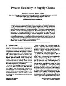
each XPDL activity type, as done in [JMN03], the effort is that to exploit as much as possible the standard AD elements and adding stereotypes only where they are necessary. Currently, however, UML doesn’t support transactional concept. We mean that if we want to underline ACID properties at the moment we can not. In order to do that we have to stereotype an existing symbol by changing its semantics. We are going to describe our extension by briefly re-introducing a typical business casestudy (already illustrated in [GCR04]) involving a customer, a wholesaler and a manufacturer, detailing how ACID properties and exception handling mechanism (both forward and backward error recovery) could be designed. A business process in order to be modeled as a transaction should ensure ACID properties. As already mentioned, in UML 2.0 there is no way to express the transaction concept and in this work we are interested in doing a first step towards it because in order to talk about efficient capture of transactions, first of all, we have to ensure transactions quality. We then propose to model a nested process through a CallBehaviorAction Metaclass with stereotype Transaction in cases in which the underlying protocol assures (relaxed or not) ACID properties. In all other cases a nested process will be modeled through a CallBehaviorAction without any stereotype. A transaction may terminate normally (according to the expectations), exceptionally or aborting the effects. In cases in which an hazard happens we propose a way to also model this circumstance. Customer Order choice
«Transaction» Agreement
Mercata Payment analysis
o: OrderAgreement
«BER» Compensate Payment
«Exception»
Product reception
PaymentFailure
delivery organization
Confirmation analysis
«Transaction» Order Confirmation
Availability Evaluation
Post conditions are not met
Post conditions are met
«Transaction» Payment
available not available
Product delivery
Situation analysis «Transaction» Production
Figure 1: Highest level diagram of Mercata Case-Study.
In Figure 1 a business process, depicted through a UML 2.0 activity diagram, is presented. There are two roles Customer and Mercata. A customer after having chosen the order and agreed (successfully executed the sub-process Agreement) about the order details, sends the order to Mercata. The Payment process, a new sub-process, takes place. During this sub-process an exception may occur. This possibility is depicted by drawing an interruptible region around the part in which the exception is supposed to happen. If during Payment sub-process a Failure Exception occurs and we must roll-back the situation, apply Backward Error Recovery (BER), because we have no means to go on in another way, a special sub-process, a UML 2.0 CallBehaviorAction with stereotype BER, has to be called.
284
Customer
Mercata
Post conditions are not met «Exception» Post conditions are met
o: OrderAgreement
o: OrderAgreement
realise
infirm payment
Figure 2: Compensation sub-process
In figure 2 the roll-back is shown: the payment is infirmed and the customer receives the notification. If Payment terminates successfully and the order is also successfully Manufacturer1
Manufacturer3
Manufacturer2 o: OrderAgreement
build p1
Material_1_Lack Exception
p1: Piece Description
launch construction
build p2 p2: Piece Description Material_2_Lack Exception
«FER» Material_Lack
p1:Piece
p2:Piece finish product
«Exceptio» Hasard
Post conditions are met
Post conditions are not met
Figure 3: Production sub-process
confirmed, Mercata will deliver the product to the customer in case of availability or will ask for production. In case of production call, figure 3 shows how the manufacturers are going to work in order to satisfy Mercata request. Manufacturer2 receives the order and establishes who has to do what. Manufacturer1 and Manufacturer3 have to produce a part of the final product. In case of lack of material exception for both parts, the two exceptions are handled by consulting the exception tree, depicted in figure 5. Exceptions are represented trough a class diagram. Among exceptions a hierarchical relationship is underlined. Following this relationship it can be established which exception has to be handled in case of concurrency. Class diagrams may be mapped into XMLSchema and passed as parameters to processes. A general Material Lack exception has then to Manufacturer2
Manufacturer1 build p1 using another type of material «Exception» Hasard
p1:piece
finish product
Post conditions are not met
Manufacturer3 p2:piece
build p2 using another type of material
Post conditions are met
Figure 4: FER-Lack of Material.
be handled and a CallBehaviorAction stereotyped FER (Forward Exception Handling) is called. In Figure 4 the same roles of Production process cooperate in order to face the exception. If at the end of FER conditions are met, a consistent state will be reached.
285
This UML 2.0 extension seeks to be a first answer to the lack of ACID properties specification already mentioned in [SD05]. Its purpose is to provide basic building blocks that may be used in order to model advanced transactional protocols. Universal Exception
Material_lack
i_Material_Lack
Figure 5: Class Diagram describing Excepion Tree.
4 XPDL: a standard workflow process definition language The Workflow Management Coalition (WfMC) [WfM05] was founded in August 1993 as a international non-profit organization. The goal of the WfMC is to promote and develop the use of workflow through the establishment of standards to define workflow terminology, to satisfy interoperability and connectivity between workflow products. One of the main activities since 1993 has been the development of standards for these interfaces. The WfMC’s reference model identifies five interfaces. Interface 1 is the link between the so-called “ProcessDefinition Tools“ and the “Enactment Service“. The Process Definition Tools are used to design workflows while the Enactment Service can execute workflows. The primary goal of Interface 1 is the import and export of process definitions. To support the interchange of workflow process definitions, XPDL has been proposed. XPDL [XPD02] uses an XML-based syntax, specified by an XML schema. The main elements of the language are: Package, Application, WorkflowProcess, Activity, Transition, Participant, DataField, and DataType. Package element is the container holding the other elements. Application is used to specify the applications/tools invoked by the workflow processes defined in a package. WorkflowProcess is used to define workflow processes or parts of workflow processes and it also consists of an oriented graph composed of nodes and edges. Nodes are activities while edges are transitions. Activity is the basic building block of a workflow process definition. There are three types of activities: Route, Implementation, and BlockActivity. Activities of type Route are dummy activities just used for routing purposes. Activities of type BlockActivity are used to execute sets of smaller activities. Element ActivitySet refers to a self contained set of activities and transitions. A BlockActivity executes such an ActivitySet. Activities of type Implementation are steps in the process which are implemented by manual procedures (No implementation), implemented by one of more applications (called Tool), or implemented by another workflow process (Subflow). Activities may have restrictions on the incoming and outcoming transitions. A restriction on the incoming transitions is called “join“, while a restriction on the outcoming transitions is called “split“. Restrictions may have a type specification: AND or XOR. If an activity node has a join restriction type AND, then all incoming edges need to be present in order to start the activity. If an activity node has a join restriction type XOR, then the activity node is initiated when at least one of the incoming edges is taken. Participant is used to specify the participants in the workflow, i.e., the entities that can execute work. There are 6 types of participant: ResourceSet, Resource, Role, OrganizationalUnit, Human, and System. Elements of type DataField and DataType are used to specify workflow relevant data.
286
Data is used to make decisions or to refer to data outside of the workflow, and is passed between activities and subflows. The XPDL 2.0 version has just been released [XPD05]. Relevant changes have been introduced in the new version. For example the possibility to represent messages exchanged among participants directly using MessageFlow entity instead of an indirect representation. Moreover the concept of transaction is finally introduced that means that an activity which is specified as transactional may terminate in three ways: normal, compensation or hazard. This is a step further towards the introduction of transaction and exception handling concepts and encourages our work in the same direction. In XPDL 2.0, in fact, a subprocess activity (implemented by Subflow) can be set as being a Transaction, which will have a special behavior that is controlled through a transaction protocol (such as Business Transaction Protocol or Microsoft Transaction Protocol). In BTP protocol, for example, participants may use recorded (before or after) images, or compensation operations to provide the roll-forward, roll-back capacity which enables their subordination to the overall outcome of an atomic business transaction. It is possible that one of the participants may end up with a problem that causes a Cancel or a Hazard. In this case, the flow will then move to the appropriate Intermediate Event, even though it had apparently finished successfully. Since our research began before the final release of XPDL 2.0 and transaction model is still is an open issue (see 7.6.13 in [XPD05]), we focused on XPDL 1.0.
5 From UML 2.0 AD to XPDL A transformation is the generation of a target model from a source model, according to a transformation definition. A transformation definition is a set of transformation rules that together describe how a model in the source language can be transformed into a model in the target language. A transformation rule is a description of how one or more constructs in the source language can be transformed into one or more constructs in the target language [MG05]. In order to provide transformation rules between UML 2.0 AD and XPDL a deep knowledge on their expressiveness seems to be necessary. Their expressiveness may be evaluated by using the workflow patterns proposed in [vdAtHKB00, WvdAD+ 04, vdA03, vdA04]. In those papers a more intuitive notion of expressiveness is considered. The modelling effort is the criterion in order to evaluate the expressiveness: a great effort in modeling implies a less powerful expressiveness. We use some of the workflow patterns that result to be relevant in our project context in order to cover the basic elements presented in section 2. In cases in which there is no direct support for the workflow pattern and a workaround solution can not be sketched easily, the language under discussion results to be not powerful enough in terms of easy-modelling. In XPDL specification we can read: “using the basic transition entity plus dummy activities, routing structures of arbitrary complexity can be specified.“ In order to supply to the lack of direct support to some important patterns, this suggestion has to be followed. We present in the following, in a declarative way, the translation rules. Some of these rules are already in use in the context of Efficient project (see [EBD+ 03] and [Esh03] for more details). In this work, however, a deep study about the possibility to nest processes has been done. Moreover a first step towards the inclusion of exception handling mechanism and transaction concept has been done.
287
AD Construct Swimlane. Each role is modeled through a swimlane.
XPDL Construct a default-value inside the Data Fields in XPDL or further investigation about the use of Participant type ROLE + participant element specification inside the activity. Swimlane
Table 1: Role representation and translation.
AD Construct B2B Action node.
XPDL Construct Activity with No Implementation. ... Table 2: Simple task representation and translation.
Using the toolset, called animator, provided by the Efficient project, users model processes through activity diagrams and data through class diagrams. There are some constrains that have to be followed. A project has obviously to be defined and inside it a package for each activity diagram has also to be defined. The activity diagram is translated into an XPDL WorkflowProcess element in [GGM05] a complete example is presented, in particular the translation of the highest level activity diagram of Mercata case-study. The package in which an AD is defined has to be translated into the XPDL package. The business domain described through a class diagram could be part of the XPDL repository. In fact in the repository it is possible to introduce all the relevant data that the workflow processes may need. 5.1 Roles Roles may represent human beings, a piece of software, a machine or something else. A role is the entity that is responsible of the execution of a task. Playing the different roles involved in the process, designers may, exploiting Efficient toolset, validate the process model. In table 1 role concept translation is shown. In particular we see that in UML 2.0 AD roles are represented through swimlanes while in XPDL we propose to use a defaultvalue inside Data Fields. 5.2 Simple and complex activities Simple activities represent executable activity nodes that constitute fundamental units of work in both XPDL and UML 2.0. In the Efficient project context, simple activities have no implementation and they serve only to show the documents processing, done manually in most cases. In Table 2 the translation rule is represented.
288
XPDL Construct AD Construct CallOperationAction. Activity implementation type Tool.