USING GRAMMAR-ORIENTED OBJECT DESIGN TO SEAMLESSLY MAP BUSINESS MODELS TO COMPONENT-BASED SOFTWARE ARCHITECTURES ALI ARSANJANI
JAMES ALPIGINI
IBM, National EAD Center of Competency, and Maharishi University of Management, 105 North D St, Fairfield, IA, 52556, USA e-mail:
[email protected]
Penn State Great Valley 30 East Swedesford Road, Malvern, PA, 19355, USA e-mail:
[email protected]
ABSTRACT Although current object-oriented analysis and design methods and modeling languages have each a rich set of semantics and syntax to support the modeling of software systems, their support for business modeling has been more limited. In addition, there is no full lifecycle support for the challenges posed by componentbased development and integration (CBDI). The transition and traceability from business models to software component architectures is by no means smooth. This paper explores extensions to current methods to fully support CBDI across the life cycle starting from business modeling and throughout the software development lifecycle. We propose Grammar-oriented Object Design (GOOD) as a method of identifying and mapping reusable subsystems in a business model to a well-mannered component-first software architecture. The latter architecture assumes the modeling and design process is based on an assembly-based paradigm of wiring prebuilt or customized components that have been designed for change and with the intent of repeated long-term reuse and customization.
KEY WORDS Component-based Software Engineering, Grammaroriented Object Design, Software Architecture, Software Patterns, Subsystem Analysis, and Variation-oriented Design.
1
Introduction
Current object-oriented methods have been augmented to include work products and activities for business modeling or have “standardized” extensions [1]. Examples of these methods include the Rational Unified Process [2], the Unified Modeling Language (UML) [3] and the IBM Global Services Method [4]. Business Extensions for the UML [1], the Business Domain in Global Services Method [4] and the Eriksson-Penker extensions to the UML for business modeling [5] directly support business modeling. Business Modeling supports software modeling by identifying the
information systems that best support the operations of the business [6], serving as a basis for functional and non-functional requirements, and as a basis of refinement into analysis and design, as well as, identifying suitable components [5]. The transition from business modeling to software modeling is not a smooth or well-understood process. Often, different teams that have different terminologies, diagramming, visualization techniques and goals perform the activities of business and software modeling. Thus a way to seamlessly map these onto one another is required.
2
Component-Based Development And Integration
There are many definitions and interpretations of what is signified by component-based development and integration (CBDI) and what defines a “component” [7]. A software component is “a unit of composition with contractually specified interfaces and explicit context dependencies only. A software component can be deployed independently and is subject to composition by third-parties” [8]. To fully realize component-ware, we propose an operational definition of how to actually build a technology-neutral components using architectural patterns, based on the need for components to be elevated from small-grained objects to cover a richer spectrum of granularity up to the enterprise-level business process. These largegrained enterprise-scale components can be wired together and adapted in a modular fashion to incorporate new behavior and business rules across business lines and product lines. We define an Enterprise Component (EC) as a compound design pattern that will allow design-time specification of technology-neutral components whose realization mechanism can be based on any standard run-time component models such as EJB or COM+. An EC is a compound pattern consisting of a Composite Mediating Façade with “pluggable” Rule Objects [9], that is, business rules that can be adaptively plugged into a component business model without violating the open-closed principle.
2.1
Issues In Enterprise Components
During the course of diverse client consulting projects across multiple industry contexts over many years, we have experienced five common threads of prevalent problems and issues. Firstly, the overall domain context view , consisting of collaborating subsystems, is often lost in favor of tactical development needs such as database tables, userinterfaces and fine-grained objects. Successful wiring of components is conducted within a well-defined domain context view; describing how subsystems collaborate to ensure business goal fulfillment across business processes and workflow steps against business rules. This can often be done in terms of a collaboration reification, which defines a pluggable workflow that can be realized in terms of a Rule Object pattern [10], so the workflow steps can be adapted to new business requirements. Secondly, in order to create a component, it is important to specify the services the component will require and provide. This component interface specificatio n not only includes the externally visible behavior (services), but also the rules governing this behavior (component “manners”) and meta-data needed for reflection and component service discovery. Thus, a holistic picture of an end-to-end business process model is necessary to show the subsystems and their perceived interactions within the business domain and software realization. This domain-partitioning and modeling of manners is the prime function of subsystem analysis, which is one of our extensions to current methods. Thirdly, there is, most often, a conceptual mismatch between the business and software models. These models are created for different reasons by different teams. Usually, the business model is ignored altogether or “magically assumed” to exist [11]. Most object methods view a software modeling process as consisting of an identification of the identity, state and behavior of fine-grained classes in the problem domain based on ambiguous business requirements that are most often incorrectly “assumed” to exist [12]. Business modeling is mentioned in only the most recent versions of the methods [1] [2] [12]. This creates a curious impedance mismatch between the business model and the software architecture that will eventually realize a well-defined subset of the business model. The mismatch stems from a “conceptual gap” between an often vague and ambiguous under-specification of what is needed and what the development team assumes is meant, which in turn, leads to unnecessary rework as tangible and executable extensible prototypes emerge with each iteration [12]. The result is yet another problem of creating design elements that are too fine-grained, interdependent and not explicitly planned for reuse. This leads to the fourth issue of component granularity: “from what level of granularity should we commence
modeling and designing components?” It must be determined if one should start (object discovery vs. subsystem discovery) by defining whole business subsystems and processes (large-grained), parts of a business process (medium-grained) or more finegrained business entities such as Customer, Account or Loan within them. Finally, a reuse level is assumed or chosen as a starting point for modeling. A common misconception assumes that the fine-grained “class” is the ultimate unit of reuse and thus of “componentization.” Our research suggests that higher levels of reuse (e.g., the “cluster” level) are more suitable for CBDI and creating resilient business-supportive software architectures.
2.1.1 Reuse Levels We have identified and used ten levels of reuse [13]. They are, in order of increasing abstraction: base class, aggregation hierarchy, inheritance hierarchy, and cluster, i.e., subsystem, framework, component, pattern, generic architecture, environment interaction meta-knowledge and technology transfer knowledge. The base class, i.e., level zero, is often the tacitly assumed reuse level that projects employ, leading to fine-grained objects that build “forests of inter-wined object graphs” which are difficult, if not impossible, to reuse in part. Our experience and research indicates that higher levels of reuse should be chosen for designing reusable components by modeling subsystems--at design-time, and realizing them as components at run-time. Methods have typically emphasized the run-time aspects of components; e.g., the UML’s icon for a component provides no guidance on what the steps are to realize one: where to start design and what to include in a component.
3
Business Modeling
A complete architectural specification of an information technology system includes information about how it is partitioned and how the parts are interrelated. It also contains information about what it should do and the purpose it must serve in the business [19]. One of today’s foremost software development challenges is the need to balance business demands for faster time-to-market with a relatively volatile set of requirements on the one hand, with the need to deliver quality, reusable code. This challenge is becoming overwhelming to software development organizations. It calls for various techniques such as ensuring adherence to Meyer’s open-closed principle [14], using adaptive object modeling [15] [16], and designing components with pluggable business rules [10]. All approaches nevertheless require strong business requirements based on an understanding gained through business modeling. The prevalent tacit expectation seems to be that during software modeling,
the gap in understanding of business needs, rules, goals and perspectives will somehow be fulfilled. It has been seen that producing business models provides a sound basis for creating suitable information systems that support the business [5]. Electronic business systems have the most to gain from an assembly-based paradigm founded on component-based development [17]. Unfortunately, balancing the need for rapid timeto-market with quality has not been easily or repeatedly achievable with the prevalent levels of ambiguity in business requirements (usually with little or no significant business modeling) and the indeterminate way they are mapped to the software architecture. This mapping will simply not work for component construction that demands partitioning of a domain into subsystems with well-defined manners. The business analyst normally bases business requirements on the knowledge the domain expert captured, but this approach does not guarantee precision or traceability. Software engineers are thus left to exercise unnecessary creativity in an area in which they are not well conversant – the business domain. This, in turn, leads to entropy in the software architecture, yielding mismatched expectations and systems that do not fit business needs.
4
Software Modeling And Architecture
Optimally, software is modeled by taking the business requirements that are an output of business modeling and performing analysis and design activities on the solid basis of correct and prioritized business needs [12]. We propose explicitly basing the initial modeling on domain-partitioned subsystems that map to distinct business domain such as Account Management, Customer Relationship Management, Rating, Billing, Product Management, Procurement and Shipping. Subsequently we suggest discovering the business rules and constraints governing the behavior of the domain plus the meta-data required to reflectively query the component for rules and services at run-time; i.e., the subsystem manners. The manners are represented as a business domain-specific language that can be adaptively modified at run-time [9].
4.1 Mapping The Business Architecture To The Software Architecture We suggest the extension of current methods such as the Unified Process of Software Development [12] with Subsystem Analysis in which the Business Domain is partitioned into cohesive business-process level subsystems with appropriate “manners” allocated to each subsystem using a use-case grammar. As an example, the following use-case is an excerpt from a complete set of use-cases for an online order management system called E-Bazaar. Especially noteworthy is the representation of a business domainspecific language in the form of use-case grammars included in each use-case description.
Make An Online Purchase This use case describes the process of making an Online Purchase using the E-Bazaar System, a hypothetical online e-business system that presents catalogs of items for customers to order over the World Wide Web. Actors. Customer (Online Customer via Web access channel), Shipping Vendor, Product Catalog, Credit Verification System, Address Sanitizer. Flow of Events: Basic Flow This use case starts when the actor initiates a Purchase for an Online Product in the E-Bazaar System after having browsed and selected items for purchase. 1. The system displays a product item ht at the user had selected. The user adds the selected product item to their shopping cart. This process (selecting and adding an item to the shopping cart) is repeated until the user is satisfied with the items in his shopping cart. In order to initiate the online purchase, the user selects Checkout. 2. The system displays an Order Summary (an itemized list of selected items and their subtotal). The user reviews the items and clicks “Continue”. 3. The system brings a billing and shipping address screen with the user’s default billing and shipping information. The user either selects the default or selects an alternative shipping or billing address and clicks continue. 4. The system displays the default payment method with the last four digits of the credit card number for user verification. The user accepts the payment method or selects an alternative payment method and selects “continue”. 5. The system displays an itemized Order. This includes items, subtotals, taxes, shipping charges and total. The user then reviews the Terms of Agreement and checks the “I agree” check box and clicks on “Submit Order”. 6. The system submits the order to the E-Bazaar and displays a confirmation of the purchase to the user, along with a thank you note and a confirmation number.
Use-Case Grammar Online Purchase = {Identification, Presentation, Selection, Purchase, Confirmation, Order Fulfillment} Identification = {Challenge User with Login, Verify UserID and Password} Presentation = {Display Menu} Selection = {Browse Product Catalog, Select a Product Item, Shopping Cart Operation, Selection} Shopping Cart Operation = { {Add Item to Shopping Cart | Delete Item From Shopping Cart | Save Shopping Cart | [Shopping Cart Operation] }, Checkout } Checkout = {Complete Order Info} Complete Order Info = {{Verify Billing and Shipping Address| Select Billing and Shipping Addresses}, {Verify Shipping Method | Select Shipping Method}}. Purchase = {Review Order, Review Terms of Agreement {Acknowledge Terms of Agreement, Submit Order | Cancel Order | Change Order to Quote}}.
control flow in a component framework through pluggable micro-workflows that implement the manners.
5
Extending The Unified Process For Component-Based Development
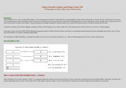
We contend that the Unified Process of Software Development can be extended, and thus used for a Component-based Development methodology. Figure 1 illustrates the Unified Process (UP) with the following extensions: Architectural analysis (1), Variation-oriented Analysis (2), Architectural design (2a), Variation-oriented Design (3) and Subsystem Design (3a) and Grammar-oriented Object Design (4). Of these, Architectural Analysis is lightly impacted and Architectural design and Subsystem Design are lightly altered.
Confirmation = {Send confirmation number to user} Order Fulfillment = {Pick and Ship Order}
The use-case grammar is a new artifact, which combines the notion of a structured use-case with one of subsystem partitioning and domain-specific languages [7]. Once a domain analysis [18] is conducted and business language analysis [19] is completed, the key abstractions of the domain are partitioned in terms of interacting subsystems that may eventually be realized as software enterprise components which are “Composite Mediating Facades with pluggable Rule Objects.[9]” Manners are assigned to each subsystem based on the Business Rules governing its behavior [20]. Subsequent Variationoriented Analysis is conducted to [10]: separate changing from non-changing aspects and features; verify what changes; handle changing aspects using patterns [21] [22]; partition the domain into subsystems and define manners for each subsystem and their interactions; and, use three layers of interface, abstraction and concrete realization in the aggregate inheritance pattern. There have been numerous examples of highly successful implementations of software based on Domain–Specific Languages (DSLs) [20][23][24][25]. A Business Language is an industry or business domainspecific language that characterizes the key manners or rules governing the behavior in the domain’s partitioned set of subsystems. Grammar-oriented Object Design (GOOD) is concerned with identifying the Business Language for a given business domain, partitioning the domain into subsystems based on Subsystem Analysis, identifying variations within the subsystem manners and applying necessary patterns [21,22] through Variationoriented Analysis and Design, writing use-case grammars that define the Manners for the subsystem and the context in which it will interact with other component interfaces, once deployed and executing the
Figure 1: A Workflow M ap for extensions to the Unified Process of Software Development.
5.1 Subsystem Analysis Example An experienced architect uses patterns that are distillations of past experience that are known to work and provide effective solutions to clients across multiple projects [21][22]. The introduction of architectural mechanisms occurs here in the UP workflow. Consider how the world would appear to an experienced software architect: instead of a large number of fine-grained objects with little reuse potential, the problem domain would be partitioned into a set of subsystems that could repeatedly be reused in product lines and families of applications across multiple projects in various business lines. In every “incarnation”, i.e., instantiation, each subsystem might be implemented in a slightly different way that depends on the component realization in the target problem domain context. However, the set of types, i.e., interfaces, and manners that define the cluster comprising the subsystem remains unchanged. Consider the following subsystems that have been identified through Subsystem Analysis, an extension to the Unified Process workflow, for the E-Bazaar example shown above:
1.
Customer Relationship Managemen t = {Account Management, Contact Management (Addresses), Security, Customer Profile and Preferences}
2.
Order Management={Order Entry {Shopping Cart Management}, Billing, Fulfillment} Product Management = {Products, Catalogs, Pricing} Inventory Management = {Fulfillment {Picking and Shipping}, Vendor Management} Financial Management ={Billing, Accounting and Bookkeeping, Accounts Payable, Accounts Receivable}
3. 4. 5.
Note that Shopping Cart Management can be thought of as part of the Order Management subsystem. However, this is architecturally significant so that in Subsystem Analysis we consider it to be a separate subsystem abstraction. The use-case grammar showing their relationship with regard to the larger-grained enterpriselevel subsystem we are calling Online Purchase Subsystem can be written as: Online Purchase Subsystem = {Customer Management, Order Management {{Shopping Cart Management (Order-Entry)}, Order-Processing, Fulfillment, Billing}, Product management}
6
References
[1] Business Extensions www.omg.org/uml.
for
UML,
OMG
.
[2] Krutchen, P., The Rational Unified Process: An Introduction, Addison-Wesley, 1999. [3] Rumbaugh, J., Booch, G., Jacobson, I., The Unified Modeling Language Reference, AddisonWesley, 1999. [4] IBM Object Technology Center, Developing Object-oriented Software: An Experience-based Approach , Prentice-Hall, 1997, pp. 192-232. [5] Erikson, Hans-Erik; Penker, Magnus; Business Modeling with UML, John Wiley and Sons, 2000, pp. 66-75, pp. 370-371. [6] Marshall, C., Enterp rise Wesley, 2000, pp. 7-26.
Modeling, Addison-
[7] Bory, Deimel, Henn, Koskimies, Pasil, Pomberger, Pree, Stal and Syperski, “What characterizes a software component?”, Software Concept and Tools (1998), Vol 19, No.1, pp. 4856. [8] Workshop on Component-Oriented Programming (WCOP’96), ECOOP’96 Workshop Reader, Springer-Verlag, 1997, ISBN 3-920993-67-5.
The above domain grammar tells us that in order to build reusable components for a larger Online Purchase Component we must build at least four other components relating to the handling of Customers, Products, Shopping Carts and Orders. Orders pertain to the backoffice activities that occur once an online purchase has been made. The Shopping Cart metaphor is used to set up the order. Once the order has been confirmed, an Order is created that is sent to Accounting (to generate an invoice or shipping list), to Inventory in order to Pick and Ship the product. Inventory sends this on to Shipping, which actually does the physical shipment.
[10] Arsanjani, A., Rule Object: A Pattern Language for Flexible Modeling and Construction of Business Rules, Washington University Technical Report number: wucs-00-29, Proceedings of the Pattern Languages of Program Design, 2000.
5
[11] Daniels, J., Cheesman, J., UML Components, Addison-Wesley, 2000, pp. 68-73.
Conclusion
Grammar-oriented Object Design was shown to be a potent combination of extending methods, incorporating DSLs from a given business domain (BDSLs) and Variation-oriented Design in order to provide a seamless transition from business models to component-based software architectures. GOOD starts by extending current object modeling techniques to include the discovery and explicit modeling of higher levels of reuse, starting from subsystems, defining their manners using a domain-specific business language, i.e., using use-case grammars, that describe the rules governing the creation, dynamic configuration and collaboration of large-grained, business-process-scale, adaptive software components with pluggable behavior, through the application of architectural patterns and representation of component manners in the BDSL.
[9] Arsanjani, A., Enterprise Component: A Compound Pattern for Building TechnologyNeutral Components, proceedings of OOPSLA 2000 Workshop on Business Components, Minneapolis, MN, 2000, to be published by Springer-Verlag, 2001.
[12] Jacobson, I., Booch, G., Rumbaugh, J., The Unified Software Development Process, AddisonWesley, 1999, pp.98-106, pp.122-130. [13] Arsanjani, A., “Analysis and Design of Distributed Java Business Frameworks using Domain Patterns”, Proceedings of TOOLS ’99, IEEE Computer Society Press 1999, pp. 490-500. [14] Meyer, B., Object-oriented Software Construction, Prentice Hall, 1997, pp. 57-61. [15] Arsanjani, A., “GOOD: Grammar-oriented Object design”, Position Paper for OOPSLA Workshop on Metadata and Active Object Models, 1998, Vancouver, British Columbia. [16] Arsanjani, A., “Dynamic Configuration and Collaboration of Components with Selfdescription,” position paper submitted to ECOOP 2001 Workshop on Active Object Models and
Meta -modeling, www.mum.edu/cs_dept/aarsanjani/ecoop2001.
2001.
[17] Allen, P., Realizing e-business with Components, Addison-Wesley, 2000, pp. 64-71. [18] Arango, G., Domain analysis: from art form to engineering discipline; Proceedings of the fifth international workshop on Software specification and design, 1989, Pages 152 – 159. [19] McDavid, D., A Standard for Business Architecture Description, IBM Systems Journal. Vol 38, No. 1, 1999. [20] Thibault, S. A. , Marlet, R., and Consel, C., Domain-Specific Languages: From Design to Implementation Application to Video Device Drivers Generation, IEEE Transactions on Software Engineering, vol. 25, pp. 363-377, May 1999. [21] Gamma, E., Helm, R., Johnson, R., Vlissides, J., Design Patterns: Elements of reusable Objectoriented Software, Addison-Wesley, 1994. [22] Fowler, M., Analysis Patterns: Reusable Object Models, Addison-Wesley, 1997. [23] Allen, B., and Holtzman, P., “Simplifying the Construction of Domain-Specific Automatic Programming Systems: The NASA Automated Software Development Workstation Project,” Proceedings of the Space Operations Automation and Robotics Workshop, (Houston, TX), pp. 407410, NASA Johnson Space Center, Aug. 1987. [24] Ardis, M., Dudak, P., Dor, L., Leu, W., Nakatani, L., Olsen, and Pontrelli, P.,”Domain Engineered Configuration Control”, in Proceedings of the First Software Product Line Conference (P. Donohoe, ed.), pp. 479-493, Aug. 2000 [25] Batory, D., Coglianese, L., Goodwin, M., and Smith, R. , “A Domain Model for Avionics Software,” Tech. Rep. ADAGE-UT-92-01, Department of Computer Science, University of Texas, Austin, Texas, Feb 1992.