Other typical IN services include call ID, automatic transferring of a call according to the callers phone number, conference calling, and voice menus.
Using Group Communication Technology to Implement a Reliable and Scalable Distributed IN Coprocessor� Roy Friedman
Ken Birman
Department of Computer Science Cornell University Ithaca, NY 14853 Abstract In this paper we explore the use of group communication technology, developed in the Horus project to implement a reliable and scalable distributed IN coprocessor. The proposed implementation can handle up to 20,000 calls per second with 12 computing nodes, can tolerate a single node failure or recovery, and can recover from periods of overload. Our work suggests that group communication technology can bring substantial bene ts, including scalability, fault-tolerance, and real-time responsiveness to the most demanding telecommunications applications.
1 Introduction The SS7 switching network architecture speci es a hierarchical structure for telecommunication switching nodes [1]. According to this speci cation, each switching node is composed of a switch and an Intelligent Networking (IN) coprocessor. The switch must be able to handle a well known set of tasks on its own: call routing for regular calls, hang-up processing, and other simple functions. If the switch detects a more complex request, it hands it o� to the IN coprocessor which can employ sophisticated software This work was supported by ARPA/ONR grant N00014-92-J-1866, and was conducted using resources of the Cornell Theory Center. �
1
and database lookups to determine how the call should be handled. (See illustration in Figure 1.) An example of a call that requires the participation of the IN coprocessor is a 1-800 number. In this case, the IN coprocessor looks up the real number in a data-base, and instructs the switch to forward the call to the real number while reversing the charge. Other typical IN services include call ID, automatic transferring of a call according to the callers phone number, conference calling, and voice menus. This architecture allows local telecommunications operators to add and enhance services in an existing switching node, and therefore to customize the telecommunications network, without having to re-implement the switches themselves. Such a capability results in a much lower cost and much higher exibility for phone companies, which typically employ this option to match the speci c needs of individual clients. Until recently, IN coprocessors have most often been implemented by a fault-tolerant computer, such as the ones manufactured by TandemTM, or StratusTM, usually connected by a dual channel to the switch, which ensures that there will be no single point of failure. Although this implementation meets the fault-tolerance requirements of the SS7 speci cations, it also has two limitations, which can be overcome by using a \cluster" style of distributed architecture to implement the IN coprocessor. First, a single machine has a limited memory capacity and/or disk space, limiting the sizes of data-bases it can handle. In a distributed implementation, the data-bases used by the IN coprocessor can be split among its elements, which allows it to hold much more information. Also, when a single machine is used, it is extremely di�cult, and sometimes even impossible, to do on the y upgrades of software, without halting the IN coprocessor. On the other hand, in a distributed, replicated, implementation, it is possible to bring down a single processor p, load the new version of the software into p, bring p up, and then repeat this procedure with the other processors, one at a time, until all processors have been updated. Assuming that the upgraded software is backward compatible, such an upgrade can take place without interfering with the services provided by the switching node. In this paper we explore the use of group communication technology, developed in the Horus project [15, 16], to implement a distributed IN coprocessor. Horus provides replication management tools which greatly simplify the task of developing such distributed applications, as well as failure detection and automatic recon guration which allows the solution to achieve the necessary fault-tolerant requirements. In addition, Horus supports high throughput and low latency communication, which are important in order to meet the operability requirements which are expected from an IN coprocessor. Although we do not have direct access to an SS7 switch at this time, our experiment seeks to be as realistic as possible. We have developed a mockup implementation of an 2
I N
SS7 Network
Switch
C o p r o c e s s o r
Figure 1: Hierarchical Switching Node IN coprocessor, such as the one de ned in the SS7 speci cations, using Horus. Using this mockup, we measured throughput and survivability of a cluster of RS/6000 workstations connected by the High-Performance Switch of the IBMTM SP2TM parallel computer. Our mockup requires that the switch receive a reply to each request for service from the IN coprocessor within 100 milliseconds; otherwise the call is dropped. Using this deadline, our implementation achieved a throughput of over 20,000 requests per second, with up to 12 computing nodes. When the load imposed on the system was 22,000 requests per second, our implementation started dropping up to 5% of the calls randomly. Additionally, we have demonstrated that our implementation can sustain a single failure, or recovery, and can also recover from short periods of overload, as soon as the load returns to normal. Taken as a whole, our results suggest that workstation clusters interconnected by high speed communication links represent a feasible alternative to the conventional architecture based on fault-tolerant processors. Clusters have signi cant price/performance advantages, and can accommodate much larger core memories than single machines. Although our work also suggests that there are limits to the scalability of clusters, we have been able to identify the major performance-limiting factors of the architecture. With further work, we believe that many of these can be reduced or eliminated, opening the door to additional scaling. Finally, this paper is written with the speci cs of IN coprocessors in mind. However, we believe that our techniques for providing fault-tolerance, high throughput, and timely responses can be used in many other applications which have similar requirements, such 3
as replicated servers and controllers. The rest of this paper is organized as follows: A brief presentation of Horus is given in Section 2. Section 3 speci es our proposed architecture. Section 4 describe how the system handles membership changes resulting from a node failure or recovery. Section 5 reports on the performance measurements we obtained, and discusses some of the lessons learned from these measurements. Finally, we conclude with a discussion in Section 6.
2 Horus { A Group Communication System Although our work makes extensive use of the Horus group communication system, brevity precludes a detailed description of Horus in the present paper. Very brie y, Horus is a high performance communication layer that supports the formation of groups of processes that can be distributed over the nodes of a distributed computing system or workstation cluster. Each process group provides an interface whereby messages can be sent and received from the group, and through which membership changes are reported. The virtually synchronous execution model, well known from a number of research and commercial systems for group computing, e.g., [8, 9, 3, 4, 13], permits the implementation of a variety of algorithms and tools over such a group. Most important to us here are tools for replication of data among the group members, performing a remote procedure call on the members, and load-balancing. More details on Horus can be found in [15, 16].
3 A Distributed Architecture for an IN Coprocessor 3.1 The Building Blocks The distributed IN coprocessor architecture we propose is illustrated in Figure 2, and consists of the following components: an external adaptor, denoted by EA, a query element, denoted by QE, and an update interface, denoted by UI, all of which are members of the same Horus process group. The EAs are designed to serve as interfaces for the coprocessor in order to communicate with the switch: The switch is connected by reliable point-to-point channels to the EAs. For reasons of fault tolerant, there are several (typically two) such EAs. The QEs have access to the data-base, and are responsible for executing the queries that are sent by the switch. We assume that each entry in the data-base is held by more than one QE (that is, the database is replicated for increased 4
availability). Finally, the UI is an interface through which updates to the data-base can be initiated. We assume that such updates will not be frequent compared to queries by the switch, and that they would usually not have such tight deadlines. For the rest of this discussion, we assume that there are two EAs, denoted by EA1 and EA2. However, our implementation is built to support any degree of redundancy by changing its parameters, and the description of the mode of operation below can be generalized to higher numbers in a natural way.
3.2 Basic Mode of Operation Whenever the switch needs to perform an IN query, it sends a query to the EAs, on both channels. After receiving a query from the switch, the EAs must propagate the query to the QEs that can handle this query. After the QEs that were assigned to this query determine the response, they report it to the EAs, which then relay the answer back to the switch. We assume that the EAs have a fast way of knowing which QEs can handle which queries, e.g., by looking at a hash table. Our work also assumes that queries are identi ed by unique sequence numbers. Hence, EA1 serves as the primary EA for all odd numbered queries queries and a backup for all even numbered queries, while EA2 serves as the primary EA for all even numbered queries and a backup for all odd numbered queries. A primary EA picks one of the QEs to handle the query, and forwards the query to this QE. In order to achieve good load balancing between the QEs, the QE for a query is picked by some deterministic uniform distribution function, among those that can service it. Notice that our system has all QEs active at all times, handling di�erent queries. When a QE receives a query, it start servicing it. After computing the reply, the primary QE sends this to both EAs, regardless of which EA has forwarded it the query. Both EAs then relay the reply on both channels to the switch. In case the backup EA does not get a reply for a query after half the expected deadline for this query, it reissues this query to one of the QEs in the same way as the primary would. However, the deterministic uniform distribution function used in this case guarantees that the QE that is chosen by the backup is di�erent from the one chosen for the same query by the primary. The QE that was chosen by the backup services the request and sends the reply to both EAs, which then relay it to the switch, again, on both channels.1 Of course, if Horus detects that one of the EAs has failed, it recon gures the membership to exclude this EA. Subsequently, the only surviving EA will handle all requests, In the current implementation we assume that the switch can eliminate duplicate replies to the same query. This is reasonable considering the fact that queries have unique identi er. 1
5
Query Element External Adaptor
Query Element
ply
Switch
Re
Query Element
ery
Qu
Distributed IN Co-Processor
Qu
(Horus Group)
ery
Rep
ly Query Element External Adaptor
Query Element
Query Element
Updates Interface
DB Manager
Upd Requ ate ests
Figure 2: System's Architecture until the failed EA recovers, or is replaced. Similarly, if Horus detects that a QE has failed, it will recon gure the group to exclude this failed QE, such that no more queries will be forwarded to it, until it has been recovered, or replaced, and was added again to the group. Our approach is slightly di�erent than typical primary-backup protocols, e.g., [2, 5, 7], since in our implementation both the primary and the backup relay the answer even when all other messages arrive on time. This is done in order to overcome a failure of one of the links between the EAs and the switch. Also, unlike usual primary-backup schemes, in our implementation the backup reissues the request without waiting for the failure detector to report a failure. The reason for this is that the deadline before the switch drops a call is on the order of a hundred milliseconds. However, unless a computing node is manually taken o�-line for service, it may take the failure detector a few seconds to detect a failure. Waiting for the failure detector would therefore increase the probability of dropping the same call repeatedly, a type of failure that is considered extremely serious in the SS7 architecture. The alternative of reducing the detection time 6
of the failure detector would result in an excessive rate of false failure detections, which would make the system too unstable for practical use. Our approach avoids this issue by reissuing a request if a reply was not received after half the deadline, even if the failure detector has not yet detected any failure. Although this has an overhead (duplicated work when the EA or QE is not faulty but merely slow), it permits the system to ride out the period between when a failure occurs and when it is detected. Note that our approach does not fall into the category of active replication [14] either. Active replication means that the primary as well as all the backups act immediately and simultaneously. In our case, the backup does not act immediately, and whenever a reply is received before half the deadline, the backup does not reissue the request at all.
3.3 Achieving High Throughput Recall that a backup EA must reissue a request if it has not received a reply within half the deadline for servicing the call. The simplest approach to this would be to set up a timer for half the deadline, and if the timer expires before the corresponding reply arrives, to reissue the request. Unfortunately, this simplistic approach is not adequate when the number of requests per second becomes very large. The reason for this is that if we set up a separate timer for every request, each one generating a separate event in the system, then the load created by these events on the system would be too high, causing a real interference with the performance of the system. Instead, we decided to aggregate requests into sets of requests that arrive at a proximity of 15 millisecond of each other. These requests are kept in a cyclic set of queues, such that every request is inserted into the current queue, similarly to what is done in [17]. (See illustration in Figure 3.) Then, every 15 milliseconds, a sweeper task scans the last queue, i.e., the one that follows the current queue, reissues all the requests which are held in this queue and for which a reply has not arrived yet, and then assigns the last queue to be the new current queue. The number of such queues is half the deadline time divided by the frequency of the sweeper plus one. This ensures that every request will be reissued, if necessary, after roughly half its deadline. A somewhat similar problem to the one described above is created by the need to send messages from the EAs to the QEs and back. If the protocol sends a separate message for each query and each reply, then the amount of tra�c generated would quickly overcome the network capacity. Also, the load created by the need to process all these messages would become larger than the actual time spent in processing queries. To overcome this problem, we bu�er queries at the EAs, and replies at the QEs, such that every 15 milliseconds a sweeper thread sends all bu�ered queries, or replies, as the case may be, in one Horus message [11]. 7
Request
Request
Request
Request
Request
Request
Request
Request
Request
Request
Request
Request
Previous "Current Queue"
Request
Request
Request
Request
Request
Request
Current Queue
Last Queue
Figure 3: A cyclic set of queues to hold requests In our initial design, each request and each reply were allocated a new Horus message, and we used a layer of Horus which bu�ers messages and then on a timely basis packs the bu�ered messages and sends them as one packed message. However, it turned out that the packing mechanism in the current implementation of Horus is not optimized for small messages, and created excessive overhead. Therefore, currently we are bu�ering requests and replies at the application level, and allocate a Horus message only when the aggregated data needs to be sent, i.e., once every 15 milliseconds. Moving the packing to the application level improved the throughput by a factor of up to 5, but slightly complicated the code of the application.
3.4 Handling Overloads The main goal of our implementation, aside from being able to sustain failures, is to make sure that as many requests as possible will get their reply within the assigned deadline. Similar to other (hard and soft) real-time systems, we use the rule that it is better to drop several requests if it seems that there is no chance of servicing them in time, than to service every request but to miss all deadlines [12]. A situation where this rule must be applied is likely to happen whenever the system 8
becomes overloaded. That is, if for some reason, the switch suddenly receives more calls than it was designed to handle. In practice, events like this occur if, for example, there is a natural disaster such as a major power failure or an earthquake. In this case, we would still like to be able to service some of the requests in time, and even more important, we would like to be able to resume normal service in which all new calls are serviced in time, as soon as the load becomes normal again. In order to guarantee this behavior, both the EAs and the QEs employ a watermarks approach for receiving new queries. That is, whenever the number of pending queries exceeds some predetermined maximum known as the high watermark, the EA, or QE, as the case may be, starts dropping all new queries that it receives until the number of pending queries drops below some predetermined minimum, known as the low watermark. After the number of pending calls drops below the low watermark, new queries are serviced as usual. Of course, the high watermark and the low watermark can be set individually for each EA and each QE.
3.5 Updating the Data-Base We assume that updates are initiated only at the update interface (UI). Whenever an update to the data-base is requested, the UI multicasts an update message to the entire group. This is done by invoking the Horus xxx cast() downcall.2 Although Horus is capable of providing ordering for multicasts (for example, by guaranteeing that all QE's see queries in the same order), the degree of ordering supported can be varied to match the needs of the application. In our implementation we found that \sender ordering" or \ fo" ordering is su�cient. Although this means that there can be very short periods in which queries that access the same data entry (phone number) on di�erent QEs will return di�erent replies, study of the SS7 speci cation suggests that this does not represent a real problem in terms of the correct behavior of the application. The real requirement turns out to be the following: Whenever a service (phone number) is canceled, it is rst reported as canceled, and only then it is actually disconnected. Thus, by the time the \plug" is pulled out, all QEs are already informed about this. To respect this requirement, our implementation is designed so that when a service (phone number) is added, it is rst \plugged in", and only then reported as added. Hence, if a QE nds a service (phone number) in the data-base, it is already available. Finally, in order to modify an existing entry in the data-base, the following steps should be taken: (a) the new service (phone number) is \plugged in", (b) a busy If there are updates that needs to be sent only to some members, but not to all of them, this can be implemented by the Horus xxx send() downcall. 2
9
signal is generated for the old service (number), (c) an update message is sent to every group member by the UI, (d) the old service (number) is disconnected. Our claim that this scheme guarantees correctness w.r.t. the customer is based on the following observations: The time to update all EAs and QEs is a few milliseconds. So, even if a customer gets a busy signal only because an update is taking place, the customer cannot distinguish between this and a real busy signal, and by the next time this customer tries to make the same call, the system will have completed the update and will treat the call in the normal manner. Moreover, if the update a�ects data-bases held by more than one switch, then it is impractical to update all these switches at the same time, or in the same order w.r.t. other calls. Thus, a scheme like this one should probably be used in any case, and our approach does not reduce availability more than would a scheme in which messages were delivered in identical (\total" order within the distributed IN coprocessor. On the other hand, using total ordering within the coprocessor would have degraded the performance of the system, and would have resulted in potentially noticeable delays during recon guration.
4 Membership Changes 4.1 Removing a Failed Member Note that whenever an EA or a QE fails, it is technically possible to continue operating without recon guring the group membership list to report the failure. This is because our backup approach does not wait for the failure detector to report a failure before the backup comes into action. However, not removing failed members from the group reduces the throughput of the IN coprocessor, increases the probability of missing deadlines, and reduces the resiliency of the distributed coprocessor to future failures. If the primary EA for a certain query, or the QE that was picked up by the primary EA for this query has failed, then half the deadline time for this query will be wasted before the backup will kick in. Thus, if something additional goes wrong, e.g., a network error or congestion, which causes slight additional delays, then there is less spare time to absorb this. Also, for half the deadline time, in our case, 50 milliseconds, the query is just waiting in vein, without actually having a chance to be serviced. For this duration of time, the query is counted as pending by the EAs, increasing the vulnerability of the coprocessor to overloads. Thus, whenever the failure detector of Horus detects a QE or an EA as failed, the system recon gures itself to exclude the failed member from the membership list. If the excluded member is an EA, then the surviving EA starts acting as a primary for all queries. If the excluded member is a QE, then no more queries will be directed to it. 10
4.2 Adding a Recovered Processor Clearly, whenever a member recovers, we would like to add this member back to the group, so it can help to share the load with the other member, and to ensure that if another member fails, there will be enough members that can continue to provide service to the switch. Similarly, being able to add new members is important to allow to scale up while the switch is running, and to support software upgrades during the life-cycle of the switch. As a group communication system, Horus has built-in tools to support the required recon guration. The only aspect that needs to be handled by the application concerns bringing the recovered (newly added) member up to date with the current state of the data base. We assume that the system's state is dumped to disk periodically, say once a day, and that log les are used to maintain updates that occur between dumps. Hence, before a recovered (newly added) processor p joins the group, it rst reads from disk the last saved state. If the log is large, it may also be advisable to read the log before p joins the group. After p has been added to the group, one of the other processors sends a state-log message to p which includes the logged updates, or just those that p has not already read. When p receives the state-log message, it applies all the updates contained in that message to the state that it recovered from disk. Afterwards, p broadcasts a state-ready message to all other members of the group, indicating to them that it has come up to date with the state of the system, and can now handle requests. If an update from the UI is received by p before it gets the state-log message, then p bu�ers the update message until it receives the state-log message and is able to apply the updates reported in that message. Following this, p replays the bu�ered update messages from the UI. Also, if by the time another con guration change happens, p did not multicast the state-ready message, then one of the old members will re-send a state-log to p, to make sure that even if due to a failure p did not receive this message before, it will eventually receive it.
5 Performance Measurements We conducted our measurements on a cluster of RS/6000 nodes of an IBMTM SP2TM parallel computer, running the AIX 3.2 operating system and the POE run-time environment. These nodes operate at 66.7 MHz, each equipped with 128 MBytes of memory. The communication was done, through Horus, over the High-Performance Switch of the 11
SP2, using an active messages interface [10]. The round-trip latency of active messages on the SP2 for 4 KByte messages, which is roughly the largest message we were sending in our experiments, is 200 microseconds. The maximum achievable throughput using active messages is 34.5 Mbyte/sec, which is well above what we needed for our experiments. Horus itself adds 200{400 microseconds to the total delay of each message. However, by aggregating requests and replies and sending them only every 15 milliseconds, we were able to reduce the e�ective delay per query (or reply) attributed to Horus to only 1{2 microseconds. A detailed analysis of the time spent in each part of the system for each request will appear in the longer version of this paper. Note that active messages were chosen since they provide an easy user space interface to the High-Performance Switch.3 The bene t of using a user space interface is that it reduces the amount of time that it takes to access the network. When using IP protocols, the interaction with the kernel for each send or receive costs several hundreds of microseconds, even though messages still go through the High-Performance Switch. When operating in high load, and when the size of the group increases, these periods when the application cannot do anything else a�ects the ability of the system to meet deadlines. Thus, the main saving by using active messages does not come from the time a message spends on the network itself (the \wire" Rather, the saving is by having a much shorter access time to the network. We estimate that by moving from IP protocols to active messages we have gained a factor of 2{4 in throughput, depending on the number of QEs. This improvement also indicates that the e�ciency of the network interface being used is extremely important for the ability of the system to scale to large number of QEs. We have measured the performance of the system in failure free runs, during a failure of a QE or an EA, and when a QE or an EA was added to the system. These measurements are reported below.
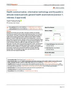
5.1 Failure Free Runs Figure 4(a) illustrates the ability of the system to handle various loads as a function of the number of QEs, when there are no failures or additions of nodes. Presented in this graph are the maximum number of calls that can be imposed on the system such that all calls make their deadlines, the maximum number such that no more than 3% of the calls miss their deadline, and the maximum number such that no more than 5% of the calls miss their deadline. These numbers were achieved by examining the system's behavior during a period of 1,000,000 calls. 3
User space interfaces for other high-speed networks, like ATM, have also been developed [6].
12
Note that the performance of the system slightly degrades as the size of the group increases. This is due to the fact that the EAs have to relay all messages from the switch to the QEs and back, making the EAs a bottle neck. In particular, the more QEs there are, the more messages the EAs have to send and receive. This seems to be an inherent problem in the architecture of the system, and future designs of switches may want to consider having several dual connections between the switch and the IN-coprocessor, which will allow to use more EAs. The switch could then send queries on alternating dual connections, which would increase the total throughput of the system. On the other hand, the number of EAs cannot grow arbitrarily, since at some point the switch will also become a bottle neck. Figure 4(b) illustrates the behavior of the system with 10 QEs. This graph presents the percentage of calls that made their deadline when the load was 20,000 calls per second, 22,000 calls per second, and 23,000 calls per second. The granularity at which these numbers were taken is 20,000 calls. Note that at the beginning of the run, a few calls miss their deadline even for a load of 20,000 calls per second. This phenomena repeated itself in many runs. We attribute this to the time required for Horus to initialize its data structures, and create su�cient caching for later usage. Our watermarks approach proved e�ective in helping the system to overcome periods in which many calls were dropped. On the other hand, this approach also contributes to the jittery behavior of the system during overload. Fine tuning of the high and low watermarks could smoothen the behavior of the system in these cases. Finally, there may be some operating systems and Horus related timing problems that during high loads also contribute to this chaotic appearance of the graphs.
5.2 Node Crashes and Recovery We have conducted two types of experiments with node failures: In the rst experiment, one of the QEs was killed after 500,000 calls (out of the 1,000,000 for which measurements were taken). In the second experiment, one of the EAs was killed after 500,000 calls. In both these experiments, the killed process did not notify its death to any other process, simulating a real crash in the system. In this case, there are roughly 6 seconds until Horus detects this failure. In these 6 seconds, it is up to the primary-backup mechanism to make sure that no calls will be dropped. Also, at the end of these 6 seconds, a view change must take place, which is a more expensive operation to do than a regular receipt of a message. Thus, potentially, a view change may also cause a few calls to miss their deadlines. In the experiments that we have done, no signi cant number of calls were dropped during these 6 seconds, when compared to the failure free runs under similar loads. Thus, 13
4
x 10 2.5
100
Percentage of calls on time
80
1.5
No loss 1
Up to 3% loss Up to 5% loss
70 60 50
20,000 calls per sec 22,000 calls per sec
40
23,000 calls per sec 30
0.5
20 10
0 2
3
4
5
6 7 8 Number of QEs
9
10
11
0 0
12
(a) System's performance as a function of the number of QEs. Presented are the number of calls that can be imposed on the system such that all calls make their deadline, the number that may cause up to 3% of the calls to miss their deadline, and the number that may cause up to 5% of the calls to miss their deadline.
1
2
3
4
5 call #
90 80 70 60 50 40 30 20,000 calls per sec
20
22,000 calls per sec 10 0 0
23,000 calls per sec 1
2
3
4
6
7
8
9
10 5
x 10
(b) Typical system's behavior with 10 QEs during failure free runs, during runs in which a node has failed, and during runs in which an EA was added in the middle. Presented are the percentage of calls that make their deadline with a load of 20,000 calls per second, 22,000 calls per second, and 23,000 calls per second.
100
Percentage of calls on time
Number of calls (queries) per second
90 2
5 call #
6
7
8
9
10 5
x 10
(c) Typical system's behavior with 10 QEs during runs in which a QE is added in the middle (after roughly 500,000 calls). Presented are the percentage of calls that make their deadline with a load of 20,000 calls per second, 22,000 calls per second, and 23,000 calls per second.
Figure 4: System's performance and behavior 14
it seems that our system was able to mask the injected failures. This seems reasonable, considering the fact that half the deadline, i.e., 50 microseconds, is much longer than the communication time and the compute time for each request. Since the system behaved roughly the same in both the failure free runs and in the runs in which one node crashed, we do not present separate graphs for these runs. Similarly, we have conducted two experiments regarding node recovery, corresponding to the experiments regarding node failures: In the rst experiment, we added one QE roughly after half the measurements time. In the second experiment, we started the system with only one EA, and added the other one after roughly half the time. From our measurements it appears that the system was capable of adding a an EA without any noticeable e�ects on its ability to meet deadlines. In particular, the results reported in Figure 4(a) and 4(b) hold for this case too. The only noticeable e�ect of adding a QE to the system was that during overload, things became slightly worse after the QE was added. This is reasonable considering the fact that the system's ability to handle calls is decreasing as the number of nodes is increased. These results are summarized in Figure 4(c). In these graphs, the QE or EA, as the case may be, is added after 500,000 calls. Notice that more calls are dropped in the right half of the graph, i.e., after adding the node, then in the left side of the graph, i.e., when the group was smaller and was able to handle more calls.
6 Discussion Our work has demonstrated the feasibility of using group communication technology that supports fault-tolerance and real-time features for building distributed IN coprocessors and other applications with similar requirements. As such, it points to important bene ts that may result when these software technologies become widely useful within industries such as telecommunications. IN coprocessors represent a multi-billion dollar hardware market, and the possibility of using cluster computing architectures could have important commercial implications. Moreover, many IN coprocessors are limited by the inability to put extremely large memories on individual processors, which leads to complex multi-level storage architectures that decrease system response time and exibility. A cluster represents an appealing way to attack this memory limit; if for no other reason than to support very large memory-mapped databases, this architecture is worthy of study. These things said, the results reported here are in some ways preliminary. To implement a real distributed IN coprocessor, there are still some potentially signi cant issues that need to be addressed. In our current scheme QEs are chosen by a deterministic 15
uniform distribution function which does not take into account the actual load in the QEs. Although this approach seems su�cient when the service time for all queries is roughly the same, it would be useful to check whether more sophisticated approaches can yield higher throughput when there is a large variance in the processing time of di�erent queries. Similarly, the timings we were using to send messages are xed. A more sophisticated ow control mechanism may also allow us to achieve better performance. Finally, it may be interesting to try to ne tune the watermarks we are using, and perhaps to use some self adjusting mechanisms to determine their optimum value.
Acknowledgements: We would like to thank Daniel Mosse, Robbert van Renesse, and Werner Vogels for many helpful discussions and comments. We would also like to thank the Cornell Theory Center people for the help and cooperation we received in using the SP2, and to Chi-Chao Chang and Grzegorz Czajkowski for making the active messages implementation available to us.
References [1] General Recommendations on Telephone Switching and Signalling { Intelligent Network. ITU{T Recommendation Q.12xx. [2] P. A. Alsberg and J. D. Day. A Principle for Resilient Sharing of Distributed Resources. In Proc. of the 2nd International Conference on Software Engineering, pages 562{570, San Francisco, CA, 1976. [3] Y. Amir, D. Dolev, S. Kramer, and D. Malki. Transis: A Communication SubSystem for High Availability. In Proc. of the 22nd Annual International Symposium on Fault-Tolerant Computing, pages 76{84, July 1992. Babao�glu, R. Davoli, L. Giachini, and M. Baker. Relacs: A Communication [4] O. Infrastructure for Constructing Reliable Applications in Large-Scale Distributed Systems. Technical Report UBLCS{94{15, Department of Computer Science, University of Bologna, June 1994. Revised January 1995. [5] J. F. Bartlett. A Non-Stop Kernel. In Proc. of the Eighth Symposium on Operating Systems Principles, 1981. In ACM Operating Systems Review 15(5). [6] A. Basu, V. Buch, W. Vogels, and T. von Eiken. U-Net: A User-Level Network Interface for Parallel and Distributed Computing. In Proc. of the 15th ACM Symposium on Operating Systems Principles, pages 40{53, December 1996. 16
[7] A. Bhide, E. Elnozahy, and S. Morgan. A Highly Available Network File Server. In Proc. of the USENIX Conference, pages 199{205, 1991. [8] K. Birman. The Process Group Approach to Reliable Distributed Computing. Communications of the ACM, 36(12):37{53, December 1993. [9] K. Birman and T. Joseph. Exploiting Virtual Synchrony in Distributed Systems. In Proc. of the 11th ACM Symp. on Operating Systems Principles, pages 123{138, December 1987. [10] C. Chang, G. Czajkowski, and T. von Eicken. Design and Performance of Active Messages on the SP-2. Technical Report TR96{1572, Department of Computer Science, Cornell University, February 1996. [11] R. Friedman and R. van Renesse. Packing Messages as a Tool for Boosting the Performance of Total Ordering Protocols. Technical Report TR95-1527, Department of Computer Science, Cornell University, July 1995. Submitted for publication. [12] H. Kopetz and P. Verissimo. Real-Time and Dependability Concepts. In S. Mullender, editor, Distributed Systems, chapter 16. Addison Wesley, 1993. [13] L. E. Moser, P. M. Melliar-Smith, D. A. Agarwal, R. K. Budhia, C. A. LingleyPapadopoulos, and T. P. Archambault. The Totem System. In Proc. of the 25th Annual International Symposium on Fault-Tolerant Computing, pages 61{66, Pasadena, CA, June 1995. [14] F. Schneider. Synchronization in Distributed Programs. ACM Transactions on Programming Languages and Systems, 4(2):125{148, 1982. [15] R. van Renesse, K. Birman, R. Friedman, M. Hayden, and D. Karr. A Framework for Protocol Composition in Horus. In Proc. of the 14th ACM Symposium on Principles of Distributed Computing, pages 80{89, August 1995. [16] R. van Renesse, K. Birman, and S. Ma�eis. Horus: A exible Group Communication System. Communications of the ACM, 39(4):76{83, April 1996. [17] G. Varghese and T. Lauck. Hashed and Hierarchical Timing Wheels: Data Structures for the E�cient Implementation of a Timer Facility. In Proc. of the 11th ACM Symposium on Operating Systems Principles, pages 25{38, Austin, Texas, November 1987.
17