using haptics in multi-robot systems (where the communication and structure is very rigid) and potential ... radiation sources. This gives the ... center of the circle on the desk to the end effector of the ..... showing the many different ways haptic feedback might help a ... ICRA Workshop on Open Source Software, vol. 3, no. 3.2.
Using Haptic Feedback in Human Robotic Swarms Interaction Steven Nunnally, Phillip Walker, Mike Lewis University of Pittsburgh
Nilanjan Chakraborty, Katia Sycara Carnegie Mellon University
Robotic swarms display emergent behaviors that are robust to failure of individual robots, although they can not necessarily accomplish complex tasks with these behaviors. The research objective is to make use of their robust behaviors to accomplish complex tasks in many types of environments. For now, it is difficult to affect swarm “goals”, and therefore difficult them to direct to perform complex tasks. The extant literature on Human Swarm Interaction (HSI) focuses on demonstrating the usefulness of human operator inputs for swarms to accomplish complex tasks. The human typically gets visual feedback of the state of the swarm and influences the robots through a computer interface. This paper presents a user study investigating the effectiveness of haptic feedback in improving HSI. We use methods developed in studies using haptics in multi-robot systems (where the communication and structure is very rigid) and potential field algorithms developed for fully-autonomous swarms to determine the benefits of haptic feedback from the semi-autonomous control algorithm. In some environments, haptic feedback proved beneficial whereas in other environments haptic feedback did not improve performance over visual feedback alone. However, presence of haptic feedback did not degrade the performance under any of the experimental conditions. This supports our working hypothesis that haptic feedback is potentially useful in HSI. INTRODUCTION Swarm robotics is characterized by using simple robots in large numbers to accomplish complex tasks. The emergent behaviors, based on the local interactions between the robots and their environment, allow the swarm to accomplish tasks even with the sensor and computation limitations necessary to produce a large group of robots affordably. Unfortunately, the algorithms producing the emergent behaviors are often only guaranteed to succeed in very controlled environments, which is not practical in real world applications. Real world applications include: search and rescue operations, military surveillance, or first responder assistance (Kira, 2009; Bashyal, 2008; Naghsh, 2008; Kolling, 2012). For instance, a swarm of robots could cover a disaster zone to search for radiation sources. This gives the decision makers more information to determine the risk of sending first humans into the area. The environments in these applications are often cluttered and unpredictable, so the swarm algorithms may need to be supplemented with effective human interaction to guide the swarm through these difficult scenarios. The extant literature on Human Swarm Interaction (HSI) focuses on finding methods for the user to influence the swarm to effectively achieve a goal using an interface that gives perfect and complete information about the swarm and the environment from a bird’s eye view (Nunnally, 2012; Walker, 2012; Kira, 2009; Bashyal, 2008; Goodrich, 2011; Kolling, 2012). The contributions are new swarm algorithms and ways in which a human operator can add utility to this new algorithm. Some HSI studies demonstrate the possibilities of decentralized swarms with few robots (Kira, 2009). Others have built models of the operator, influencing a decentralized swarm (Cummings, 2004; Kira, 2009; Coppin, 2012). Some studies look at specific applications and analyze techniques for accomplishing tasks through simulated environments (Nunnally, 2012; Walker, 2012; Bashyal, 2008; Naghsh, 2008; Kolling, 2012; Coppin, 2012).
In the HSI literature, the swarm state is usually fed back through the visual channel. Some formation control experiments (Secchi, 2012; Franchi, 2011; Rodriguez-Seda, 2010; Lee, 2011) in which robots maintain rigid spatial relations, have explored the use of haptic feedback devices to give users tactile information about the state of the robots and also allowed the users to control the system by giving inputs through the haptic device. The force fed back to the humans contained information about the deviation of the centroid of the formation from a planned path and proximity of robots to obstacles. This research has focused on designing force feedback laws to make the overall system robust to communication delays and was tested on systems with few robots in simulation (Secchi, 2012; Lee, 2011). Haptic feedback laws for dealing with changing topologies as the robot system moves through obstacle filled environments, so that the robots may traverse the obstacles quickly without collisions, have also been developed (Franchi, 2011; Rodriguez-Seda, 2010). Although the use of haptic control has demonstrated success for formation control in completing tasks like information foraging where there are rigid structural constraints on the robots, it is not clear whether haptic feedback information would be useful in controlling swarms. Therefore, in this paper, our goal is to study the utility of haptic feedback in influencing decentralized swarm robotic systems, where the tasks are specified at a high level (e.g., find as many targets as you can in a given environment) and the connection topology of the swarms is flexible. The task for operators is to find targets in four obstacle-filled environments with different features. We use a between-subjects design for this study, i.e. half of the subjects are given haptic feedback to control the swarm along with visual feedback about the positions of the robots, and half of them are only given visual feedback about the position of the robots. The experiment, interface, and robot control algorithms are explained in the EXPERIMENT section. The RESULTS section discusses the
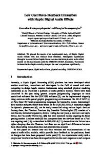
Figure 2 Participants used an Omni Phantom device and mouse to influence the swarm and manipulate the interface respectively. Figure 1 The GUI used for every condition of the study. The left side shows the robots’ estimated positions, obstacles, and marked targets. The right side shows the Force Feedback and the Input Force.
results of the user study. Finally, the findings and future works of the study are presented in the DISCUSSION section. EXPERIMENT Interface Stage v. 3.2.2 (Gerkey 2003) was used to simulate the environment, the targets, and a swarm of 30 P2AT robots, which is a simulated, four-wheeled, skid-steered robot. The graphical user interface and robot controllers are implemented using the Robot Operating System (ROS) (Quigley 2009). The interface for this study is similar to that of (Nunnally, 2012; Walker, 2012), see Figure 1. The users have a bird’s eye view of the simulated area. The participant can translate and zoom the view port using the mouse. Robots appear as circles with lines pointing in the direction of their heading. Each robot turns the color of a target if it detects one within its sensing range. Targets are only marked on the interface and counted as found when a five of robots detect the target. This compensates for sensor error, as explained in the next section. The threshold requires the users to maintain a cohesive swarm in order to complete the task. Obstacles, if shown, appear in the interface in black, while traversable areas are white. A Phantom Omni device is used for participant input by translating the device’s coordinate system to a frame on the desk next to the monitor, see Figure 2. The vector from the center of the circle on the desk to the end effector of the Phantom device gives the human input force described in the next section. The Input Force panel to the right of the view port displays the vector of the input force taken from the Phantom device so the participant does not have to look away from the screen to adjust their input. The vector is broadcast to the swarm and used to influence their path, as shown with 𝐹ℎ in the next subsection. The participants are made aware of the difficulty of controlling multiple swarm groups with only one input source without a method of selection during their training period so that they are encouraged to keep the communication graph of the swarm connected. The Force Feedback panel above the Input Force panel shows feedback
Figure 3 The closer the robots are, the stronger the repulsive force, the further the robots are, the strong the attractive force. The robots stabilize to the neutral zone without 𝑭𝑜 and 𝑭ℎ .
from obstacles which will be discussed as 𝐹𝑜 in the next subsection. Robot Control Algorithm
The robot control algorithm is based on the vector field algorithm used in (Howard, 2002) which uses repulsive forces from other robots and obstacles to deploy robots for maximum covering. An attractive force is introduced between robots to help maintain connectivity. The resulting algorithm is similar to Craig’s (1986) “boids” algorithm for simulating flocking. Each robot determines its motion by calculating the potential field given by 𝑭 = 𝑭𝑜 + 𝑭𝑟 + 𝑭ℎ with the forces due to obstacles, other robots, and human influence, respectively. The robot moves in the direction of this vector and the speed given by the magnitude, although the magnitude is generally greater than the robot’s top speed. More precisely, let 𝑜 ∈ 𝑉(𝑞𝑖 ) be all obstacles in range of robot at location 𝑞𝑖 and 𝑟𝑜 = |𝑞𝑖 − 𝑞(𝑜)| and 𝒓𝑜 = 𝑞𝑖 − 𝑞(𝑜), then: 𝑭𝑜 = −𝑘𝑜 ∑𝑜∈𝑉(𝑞𝑖)
1 𝒓𝑜
𝑟𝑜2 𝑟𝑜
(1)
Similarly, let 𝑟 ∈ 𝑉(𝑞𝑖 ) be all robots in range 𝑟𝑖 of 𝑞𝑖 and 𝑟𝑟 = |𝑞𝑖 − 𝑞(𝑟)| and 𝒓𝑟 = 𝑞𝑖 − 𝑞(𝑟) and 𝑛𝑏 be the beginning radius of the neutral zone and 𝑛𝑒 be the ending radius of the neutral zone, then:
used as to encourage participants to keep the swarm connected through its communication graph. Environments
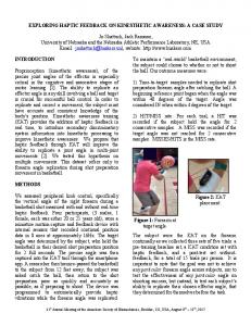
Figure 4 Four environments used in the study. The robots always started in the lower right corner: (a) Math, (b) Speed, (c) Control, and (d) Hidden (note that the participants cannot see these obstacles).
𝑭𝑟 = �
−𝑘𝑟 ∑𝑟∈𝑉(𝑞𝑖)
𝑘𝑟 ∑𝑟∈𝑉(𝑞𝑖)
1 𝒓𝑟
𝑟𝑟2 𝑟𝑟 1
,
𝒓𝑟 (𝑟𝑖 −𝑟𝑟 )2 (𝑟𝑖 −𝑟𝑟 )
𝑞𝑖 < 𝑛𝑏
, 𝑞𝑖 > 𝑛𝑒
(2)
This disperses the robots, while the attraction dissuades breaking the communication limitation of 4 meters, see Figure 3. Finally, let ℎ be the input force vector from the Phantom device and 𝑟ℎ = |ℎ| and 𝒓ℎ = ℎ and ℎ𝑚𝑎𝑥 be the magnitude of the maximum allowed force, then: 𝑭ℎ = 𝑘ℎ
1
𝒓ℎ
(ℎ𝑚𝑎𝑥 −𝑟ℎ )2 (ℎ𝑚𝑎𝑥 −𝑟ℎ )
(3)
The constant values in this study are 𝑘𝑜 = 5, 𝑘𝑟 = 3, 𝑘ℎ = 7, 𝑛𝑏 = 2.5, 𝑛𝑒 = 3.0, ℎ𝑚𝑎𝑥 = 4. The max speed is 0.6 m/s. This is the normal for most environments, although these values change for the Speed environment and will be discussed in the next subsection. This balances good area coverage with the risk of breaking communication before attraction can take effect beyond the neutral zone values. The robot senses other robots and obstacles within a 360 degree field of view using a 4 degree resolution. Average 𝑭𝑜 across all robots is shown in the Force Feedback panel in Figure 1 for all conditions and felt in the Phantom device, if the participant is in the haptics condition. The robots’ faulty target sensors miss at a rate of 𝑝𝑛 = 𝑟−𝑑 2 ) where 𝑑 is the distance to the object, 𝑟 is the range (1 − 𝑟 of the sensor, and 𝛼 is the decay rate set to 4. The sensor may also report a false positive. Occurrences of false positives were recalculated at an interval 𝑡𝑟 equal to some randomly sampled value between 6 and 10 seconds for each of the 30 robots. When a false positive occurred, an imaginary target was reported at a randomly chosen position at the edge of the target sensor’s range. The automated target marking system only marks a target when five robots simultaneously sense a target, using redundancy to compensate for errors from faulty sensors. This error and method of overcoming the error is
The participants worked to find as many targets as possible in four different obstacle filled environments. The starting position of the robots was in the bottom right corner, and each environment contained 60 targets. The first environment is a corridor maze called Math, see Figure 4(a). The width of the halls was such that the robots could mark targets along the walls if the swarm traveled down the center, but there were choke points and traps which could slow the participant down. The participant was instructed that the optimal strategy is to avoid the traps. Single digit addition problems blocked the view port every ten to fifteen seconds, leaving only the side panel with the Force Feedback and Input vectors visible, and remained up until participants responded by keyboard correctly. Normal operation occurred behind the math problem. This condition corresponds to a situation in which navigation is a secondary task and an infrequent primary task may require full visual attention at certain times, i.e. checking video surveillance while directing the swarm. The second environment is structured around many decisions called Speed, see Figure 4(b). The dead ends and intersections require focus and decision making for operators to determine the best path to explore as much area as possible in order to find as many of the targets as possible. The distinctive feature of this environment is greater speed which required changes in the force constants to avoid wall collisions. The speed was set to 1.0 m/s and the constants were set to 𝑘𝑜 = 10, 𝑘𝑟 = 4, 𝑘ℎ = 5. The change in speed is to further the attention and focus required to make quick decisions when covering the environment. This new configuration created a volatile swarm which was more likely to break up around obstacles when pushing against them. The third environment is a structured office type environment without obstacles in the rooms called Control, see Figure 4(c). This was used as the control world without special features. Participants were told to explore the rooms thoroughly before moving to the next one, as doorways slow the swarm down and spread them out. The final environment is structured with obstacles with edges and concave corners requiring exploration called Hidden, see Figure 4(d). In this environment the obstacles are hidden, so the participants had no idea where the obstacles were, except by observed behavior, side panel information, and haptic feedback for the haptic condition. The participants were told it was an office structure with obstacles in the room, and that the best strategy was to sweep the rooms, avoiding a lot of force from the walls and then finding an exit. They were also instructed to use marked targets as landmarks near exits in case the room was a dead end. Participants The study was a between-subjects design. Thirty-two paid student participants from the University of Pittsburgh were
Figure 5 Box plot around the median number of targets found in each trial across conditions and environments. Each box represents sixteen trials.
/Sec
Figure 6 Box plot around the median performance efficiency in the Math environment. Each box represents sixteen trials.
Figure 7 Box plot around the median of the ending measure of connectivity in the Control environment. Each box represents sixteen trials.
divided into two groups. One group received visual and physical force feedback in the Phantom device as described above, hereafter referred to as the haptics group. The control group received only visual feedback. All other variables remained constant. Participants were given an explanation of the robot control algorithms, interface, and importance of a cohesive swarm, after which they were given a 10 minute practice period to gain experience and ask questions. As preparation for the Math environment, a problem popped up every thirty to sixty seconds. Environments were presented in random order, and the participants were given fifteen minutes in each environment to find as many targets as possible. RESULTS Results are presented for performance and measures of connectivity in swarm communication topology. Comparisons between conditions and environments were tested with an
ANOVA. Because of excessive variability in our data and lack of prior work in the area we have chosen to report marginal differences that may suggest possible directions for future research as well as substantiated differences meeting conventional criteria. In Figure 5, the Control and Speed environments both show a marginally significant performance increase for the haptics condition, (F=2.653 and F=2.606, respectively p