via TCP/IP and not to make the functionality of the underlying domotic com- ponents .... can instantiate them to obtain a nice graphical access point to the administra- tive tasks on ... related know-how and the Jini framework was ready to use.
Using Jini to integrate home automation in a distributed software-system Peter Rigole, Tom Holvoet, and Yolande Berbers KULeuven, Department of Computer Science Celestijnenlaan 200A, B-3001 Leuven Belgium {peter.rigole, tom.holvoet, yolande.berbers}@cs.kuleuven.ac.be
Abstract. The last few years, a tendency arose to integrate various programmable devices through ever expanding computer networks. One particular domain in which this evolution stood out clearly is home automation. The EIB1 standard defines a home automation solution that consists of a network of cooperating components with little computational power. Bridging the EIB network with a computer network allows software to interact with these EIB components. However, past attempts to link EIB components with computer networks fell short in dynamism, automatism or user friendliness. In this paper we present a distributed software framework that overcomes these issues, and is capable of automatically generating a software model based on the configuration of the components on the EIB fieldbus. A framework that can be used in this perspective is Jini. Its excellent capabilities for dynamic reconfiguration and its proven deployment in domestic and office environments make it an appropriate candidate for supporting home automation systems.
1
Introduction
Home automation is well known as a technique to create a more comfortable living environment for inhabitants of modern buildings and to fine-tune these conveniences according to their desires. Classic systems usually work just the other way around: the inhabitants must adapt themselves to their surrounding environment because the electric installation was integrated statically when the building was constructed. Home automation typically controls illumination, shutters and heating, but also security, power saving and economic use of energy. Till now, domotic2 installations are typically closed systems in which the components only interact with each other using some low-level communication protocol. Few software environments exist that can communicate with the home automation components, but none that meets the needs of nowaday’s network and ubiquitous computing availability. We developed a framework that brings a new approach to the integration of small embedded devices like domotic components 1 2
European Installation Bus Domotics or home automation. We use these terms interchangeably in this paper
2
Peter Rigole
into a distributed computing environment. The EIB home automation system is introduced in the following subsection, followed by our system-requirements and a description of the interconnection between home automation and software. 1.1
Home Automation
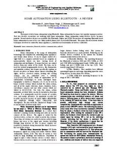
Home automation usually consists of various kinds of small devices which are interconnected via a fieldbus. The EIB domotic system we use, is a decentralized system where each component directly addresses its destination components via a communication protocol that uses multicast messages. These messages allow a component to control multiple other components with one single telegram3 . Special group addresses are used to address a collection of domotic devices. Each domotic component consists of two parts: its bus coupling unit and the end-user hardware component, which is usually referred to as the application module (AM). This can be a switch, a relay, a thermometer,. . . The bus coupling unit takes care of the communication on the EIB-bus and is used by the end-user hardware to interact with the other domotic devices. To perform this interaction, the BCU has access to addressing tables, stored in its built-in flash4 memory. These address tables are defined in the first part of the memory and are bound to the solid specifications of [1]. The remaining part of the flash memory can freely be used by the application program5 designers to store user-configurable parameters used to fine-tune the application module. Figure 1(a) shows an example of an application module (a two-button switch) and its corresponding bus coupling unit. The two parts are sometimes build in one piece. The group addresses in an address table are grouped in a number of sets and each set is assigned to one communication object, which is a concept that reflects the various functionalities of the application module in its BCU. Each of these communication objects is able to send a telegram to a group address and/or to receive telegrams from one or more group addresses. A simple example might clarify how this works. Figure 1(b) shows a possible configuration with two lights and a switch. A double relay (a binary output component) with built-in BCU switches the two lights. The BCU’s application program has two communication objects, one for each relay. The first communication object (C1) listens to the group addresses 1/2/0 and 1/2/2, the second (C2) listens to 1/2/1 and 1/2/2. When the switch now sends a telegram to group address 1/2/0 with data value 1, then the relay will switch the first light on. If the switch sends a telegram to 1/2/2 with value 0, then both lights will get switched off, because their communication objects both listen to 1/2/2. The part of the application program that can be implemented freely by the manufacturers of domotic components typically defines extra parameters that are used to configure the application module. A relay with a timer for example, needs to be configured with the time period to leave the light on. Being the main 3 4 5
a telegram is a message entity on the EIB fieldbus, like a packet in TCP/IP networks flash or EEPROM, electrically erasable programmable read only memory the application program is the name for the whole program in the flash memory
Using Jini to integrate home automation in a distributed software-system
(a) A BCU and AM
3
(b) A button that switches lights.
Fig. 1. Domotic components
access point to the component, both the addressing tables and the free part of the BCU is readable and reprogrammable via the fieldbus itself, which allows us to add automatic configuration extraction and reprogrammability features in our framework. This way, the framework is able to generate a software representation of the domotic network, based on that memory content. Unfortunately, since there is no standardisation for the memory location of additional parameters, the content of the free part is useless without external information about it. Its management is in consequence not generalizable, which limits the functionality of a generic software model to the level of configuring communication objects and their group addresses. We go beyond the generic part by adding object request broker functionality that loads extensions of the basic framework based on the signature of the application program in the flash memory. The content of the flash memory of components is accessible through the EIB bus by using a software driver6 and a serial interface connecting a PC to the EIB bus. EIB devices are then addressed by using a unique physical address. 1.2
Software integration
The framework we present in this paper is able to fully integrate the functionalities of a home automation system into a distributed software environment. We achieved this by proposing the following essential requirements before we began: – The framework should offer all the functionalities of the components on an EIB home automation system to software or to users on a computer network (switching lights, moving shutters, controling the heating,. . . ) – The framework should allow one to reconfigure and reprogram the devices of an EIB domotic system (allocating new group addresses to a communication object, adjusting parameters,. . . ) – The framework must be independent of a particular domotic configuration (e.g. the configuration in some building). – The framework must be dynamic. When one changes the home automation system (e.g. by adding a new component), the framework should take these changes into account and adjust the software representation to reflect them. 6
We used the driver of JNet Systems[2]
4
Peter Rigole
– The framework must work automatically, which means the software representation of a concrete EIB configuration is not defined by hand, but automatically generated by the framework instead. – The framework should work in a distributed environment. – The framework should offer user friendly interfaces to its users. Three important solutions have already been worked out to construct a bridge between EIB home automation and a software environment. The EIB Association (EIBA[1]) was the first to develop a tool, the ETS tool, which is mainly used to program and configure EIB compatible devices. It offers services only to the computer on which the tool runs. Its successor, the brand new version of ETS, called iETS, also offers Internet connectivity towards the EIB bus. However, the main goal of iETS is to allow remote maintenance on EIB networks via TCP/IP and not to make the functionality of the underlying domotic components available to software connected to the computernetwork. The ETS tool needs a project file of an EIB configuration to adapt the application programs of its components, which makes it unfit for use in an unknown EIB environment. The second framework was built by a company called JNet Systems[2]. They developed the EIBLET model, which is a high-level Java API7 for building agents that control one or a collection of domotic devices in a building. Since a programmer must construct new agents for each new home automation installation, we can’t call the EIBLET framework neither dynamic nor automatic and definitely not independent of a concrete domotic configuration. The last framework is a Java implementation originating in the work of Wolfgang Kastner and Christopher Kr¨ ugel[3] about Jini connectivity for EIB networks. They used Jini8 to offer services in a distributed manner. They also worked out an agent-based solution in which each agent is a service on the network that handles a set of home automation functionalities. An agent might for example manipulate the illumination in a room (lightAgent). As you can see, there is a similarity with the EIBLET solution and it meets our distributed requirement, although there is no API provided to construct agents. Each new agent needs a fresh implementation, even the Jini part needs to be re-implemented each time. In other words, the agents have to be build on demand of the inhabitants of the building. Again, this solution lacks some degree of dynamism and automatism. Unfortunately, none of the existing solutions fully meet our suggested requirements. In the following section, section 2, we start with a description about how Jini works and how it can be used to implement distributed software. We explain how we modelled our framework in section 3, followed by some Jini related work in which we compare Jini to the Web Operating System[4]. The Web Operating System also presents a way to build distributed software like Jini, but there are some conceptual differences which lead to a complete different implementation. Finally, a conclusion is given in section 5. 7 8
Application Programming Interface More details about Jini will be discussed later in this paper.
Using Jini to integrate home automation in a distributed software-system
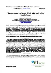
(a) The proxy design pattern
5
(b) Controlling the service
Fig. 2. Using the remote proxy design pattern
2
Jini
2.1
About Jini
Jini[5] is a framework written in Java and launched by Sun Microsystems almost three years ago. It is designed to build distributed network applications in an easy way. The services in a Jini community9 announce themselves on the network dynamically: they come and go as they like. A central service on each network, the lookup service, keeps an actual view of its surrounding services by requiring that each Jini service seeks a lookup service to register itself with. The lookup service is found by means of a multicast discovery protocol on the local network. A leasing mechanism ensures that there are no invalid references to services. When a lease expires before it gets renewed, the service is considered to be unavailable and is removed from the lookup service. The global result is a federation of spontaneously joining and leaving services. The registering procedure for services and the lookup procedure for clients is done via method calls on a remote Java object, which is obtained as the result of a successful discovery. When a service registers with a lookup service, it gives the lookup a serialized10 proxy object that has a remote reference to the service. The remote proxy design pattern [6] used here is illustrated in figure 2(a). The clue is that the service is always referred to as if it were its interface, so the proxy can play the role of a local representation for the service. The proxy simply redirects every method call to its service via remote method invocation. Figure 2(b) shows us the resulting situation: the client has direct access to the services it needs. A clever query mechanism allows clients to find the services they need via the lookup service. Three kinds of elements can be combined in the query to seek a service. The unique identifying number of a particular service is the first option. This is the easiest way, given that you know the number of the service you want. The second way is to search based on the interfaces of the services you are willing to find. The interfaces implemented by Jini services, are very 9 10
a Jini community is usually called a federation serializing means transforming an object into a byte stream
6
Peter Rigole
important because they define the type of the service and the way to interact with them from within clients. The final alternative is a template-matching query mechanism in which you use attributes to search with. Attributes are objects attached to Jini services which describe the service. To perform the query, you just have to define the query boundaries by instantiating a template-attribute with the values you want the service to have and use it in the query. The last two options are powerful query mechanisms, because the polymorph nature of interfaces and attributes can be utilized to narrow or broaden the search. If you have an inheritance structure where ColorPrinter and BlackWhitePrinter inherit from Printer, then both color printers and black and white printers are found when the interface for a regular printer is used. Queries like ’find all color printers that do 600dpi, located at the second floor of our department’ are a walk in the park for Jini when the services are modelled well. 2.2
Using Jini
It should be easy to meet the distributed requirement in a system by putting the Jini-engine under the hood of the framework. However, in reality, this doesn’t seem to be true. The reason is there is no high-level API available for Jini. Hence, lots of code has to be written all over again each time one wants to create a Jini service or client. Because this would lead to a large overhead in code and development time, we wrote a small framework that can easily be reused for each Jini service. The framework contains one basic class (BasicService), which has to be extended by each new Jini service. This extending class should implement the ’protected Object createProxy()’ method, which returns the proxy object when lookup services ask for it. This returned proxy object should, of course, apply to the pattern shown in figure 2(a). The interface on top of that figure has yet to be defined to complete the pattern. It defines the way to interact with the service and should be provided by the designer of the new service. All other functionalities (discovery, lookup, leasing,. . . ) are taken care of by the BasicService and an extendible default implementation is present for the important Jini related features (e.g. default attributes). The framework also implements the standard administrative interfaces of Jini, so that administrative tasks can be performed remotely on the service. A recovery mechanism is built-in as well. It saves the volatile data of each service automatically to disk every now and then. This data can be used at startup to initialize the service. The result is a small framework that allows us to write a Jini service with very little code. We created an analogue framework for Jini clients in which only the kind of service you’re interested in has yet to be defined. When that service is then found via a lookup service, its proxy is past as a parameter to a method that should be overloaded within the new client.
3
Modelling Home Automation
Our framework is based on an extendible model, which describes a domotic component from its lowlevel basics: its application program. The addressing tables
Using Jini to integrate home automation in a distributed software-system
7
and the communication objects of the application program are the common denominator for all EIB home automation devices, while their application module can be arbitrarily complex. More details about the design aspects are given in de following subsections. 3.1
Layered structure
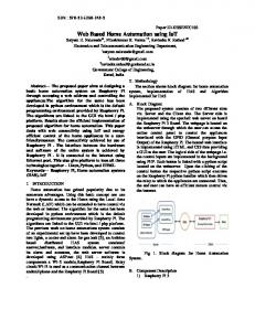
The framework has a layered structure that reflects the different levels of abstraction in the model. Figure 3 nicely displays this structure. Services from one level use services of other levels. This way, all concepts remain logically separated. We continue with a description of each level. Bus Communicator Service This service is offered on a machine with a physical connection to an EIB fieldbus and takes care of reading and sending telegrams on the bus. By adding a remote listener to this service, interested entities can get notified when a new telegram arrives. It is also possible to read the memory content out of a component’s flash memory, or to write new data into it. We used the buscomunicator API of JNet Systems [2] to implement this bridge. Busdevice Service This service is actually the core of the framework. Each component on the EIB bus will eventually be modelled by this busdevice service, or by one of its more concrete subclasses. It offers all the functionalities of the real component. A binary output for example will be able to send an ’on’ or ’off’ message to each of its outputs. The possibility to reconfigure the EIB device (e.g. changing group addresses connected to communication objects, adjusting parameters) is also provided at the level of this service. Because the default implementation of this service can’t contain the component specific configuration details (like its parameters), subclasses that know more about the content of the manufacturer’s application program will often be used. The busdevice service utilizes the underlying bus communicator service to interact with the fieldbus. Section 3.2 reveals more implementation specific details about this service. Service Controller Since the framework needs to start a matching busdevice service for each component on the EIB bus, there is a need for some controller to assign this task to. A service controller is used to keep the consistency between the state of the devices on the fieldbus and the software services. It is able to scan all physical addresses to check which components are available. When a component has not yet a service running somewhere on the network, the service controller can then initialize a new service for it, based on its memory content. Because of performance reasons, the service checks first whether there is a recent version of that memory available on persistent storage. All this ensures that the system can start up services automatically, whitout human intervenience. In addition to this automatic-property, all this occurs in a dynamic way. A library with application programs and a classloader are put in action to start
8
Peter Rigole
Fig. 3. The hierarchy of EIB bus services
the corresponding concrete implementation. When no such implementation is available, the default busdevice service is used, which offers the functionalities of an EIB device at the level of its communication objects. The component’s memory content is read out and interpreted to initialize this Jini service. Logic Services and User Programs The layer of logic services presents a real world representation of some services to create an easier to understand view for the users of the framework. A binary output for example is actually a relay, which can switch something on or off, but the device it switches is not known at the lower levels. A logic service covers this issue. It models the concrete physical situation behind some of the components. A logic service might, for example, control all the shutters in a room or building, or the lights in the living room. The top-level layer on figure 3 consists of user programs, they are end-user applications that use all or parts of the framework. 3.2
Implementation aspects
The BusDevice class has a central position in our busdevice model. It extends BasicService and provides a BusDeviceProxy and a default interface, which is already enough to make our component Jini-enabled. By employing a BusCommunicatorClientFactory, the busdevice service can generate a client that communicates with a buscommunicator (cfr. the bottom of figure 3). As facade11 for an EIB component service, it brings all the functionalities of the component (sending data to certain group addresses, adding listeners to communication objects, programming the component,. . . ) to the open world of Jini federations via a general interface, which is available in the framework for busdevice clients. Each busdevice also automatically adds some GUI-attributes to its federation. Clients can instantiate them to obtain a nice graphical access point to the administrative tasks on the service and to the communication objects of the device. All communication objects are listed in de graphical representation, together with 11
cfr. the Facade design pattern ([6])
Using Jini to integrate home automation in a distributed software-system
9
their data value. The data of a communication object that is allowed to send12 , can be changed and sent on the fieldbus with a simple click on a button. Figure 4 shows a client that instantiated the GUI-attributes of two services. The BusDevice conceals an ApplicationProgramController object that handles all application program related features. It has a reference to an ApplicationProgramInterpreter object which is able to convert the raw binary representation of an application program to CommunicationObject objects. These are then linked to the group addresses (GroupAddress objects) they listen to, or to which they can send telegrams. Both group addresses and communication objects are also used as attributes of the Jini service. This way, by using them in their lookup procedure, clients can easily look for services that send or receive telegrams to certain group addresses. Beside a reference to an interpreter, the controller also has a reference to an ApplicationProgram object. This object is useful to change the application program in its high-level representation, what makes it easy to let communication objects send or listen to new group addresses, to adjust parameters,. . . Once changed, the object can easily be transformed to the raw binary format by the interpreter again, ready to load into the BCU’s flash memory. As you might think now, this framework does not cover the functionality of all domotic components, but only what they all have in common: their protocol to send telegrams to each other. Although this covers the better part of the interaction, there is still a need to offer interfaces that are more adjusted to the underlying application program. Therefore, concrete bus device services should extend the BusDevice class and let it offer easier to use interfaces that allow the user to change the component’s parameters, or it can provide easier to understand methods (e.g. ’switchRelayOne()’ when the component is a binary output). To meet this need, and because Jini requires standarized interfaces, we created a hierarchy of interfaces which classifies the components as it is done in the libraries for the ETS Tool. Mind that these subclasses of BusDevice should be added to the library that is used by the service controller (cfr. figure 3), to ensure these classes can be loaded and initialized by the controller.
3.3
Simulation
If we take a step backwards now, we can look at our framework in an entire different way. We can use the federation of busdevices as a simulator for our home automation system. We simply have to disconnect it from the physical bus and replace our buscommunicator service with a dummy one that simply acts as a loopback device. In this state, we can apply changes to the system and do some tests on it by letting the components send telegrams to each other (they get delivered thanks to the loopback device), without affecting the configuration of our home automation. Once the new configuration looks fine in the simulation, we can apply the adjustments to the memory of the real EIB devices. 12
e.g. a communication object of a sensor like a button or a thermometer
10
Peter Rigole
Fig. 4. GUI attributes
4
Jini related work
Choosing Jini was straightforward for us, because we had all the necesary Java related know-how and the Jini framework was ready to use. There are, however, other distributed middleware solutions available. One of them, also using Java as programming environment, is the Web Operating System[4], or WOS in short. Although the system is still under development and not completely ready to use, it is interesting to have a look at it, and compare it with Jini. The WOS begins with the concept of an operating system that offers resources to its users. Whereas a standard operating system keeps track of all resources available on a machine, a distributed operating system can not keep track on all the available resources any longer, since it runs on machines scattered all over the network. To solve this, some kind of dynamism was built in the framework, based on a demand driven technique called eduction[7]. The eduction engines are the kernels of the WOS, which reactively answer to the requests of users or other eductive engines. It is very important to notice that the WOS is a versioned system. Different versions of WOS services can simultaneously be available on the network. This is a important conceptual difference with Jini as it influences the used discovery protocol and the way to interact with services. The most important consequence is that no interfaces are agreed upon in advance, which define the cooperation between clients and services in Jini. We will compare now briefly some features of the Web Operating System with Jini. The discovery protocol Jini uses a simple multicast protocol for discovering new services. The WOS, on the other hand, utilizes a more complex two-level communication protocol: the WOS Request protocol (WOSRP[8]) and the WOS Protocol (WOSP[8]). The WOSRP is the version independent layer, which looks up WOS servers and compares its version to the others to find compatible ones. The WOSRP iteratively broadcasts messages beginning with the nearest networks to networks further away to build a view of its environment. Once discovery is completed, the more powerful WOSP protocol is then used between
Using Jini to integrate home automation in a distributed software-system
(a) WOS eductive engines
11
(b) Jini lookup hierarchies
Fig. 5. WOS versus Jini hierarchies
mutual compatible WOS nodes. Jini on the other hand, only lets each service register itself with the local lookup in order to get found by its clients. Lookup Lookup is the term used for searching services based on certain conditions. The WOS keeps for this purpose references to its services in resource sets, which are found via eductive engines. These eductive engines query the resource sets in their immediate environment. When the eductive engine can’t handle the request by itself, it forwards the request to other eductive engines, until the resource finally gets found. Figure 5(a) shows this propagation of requests. Similar constructions can be seen in Jini federations, although they are not automized as it is the case with eductive engines. Jini services usually register only themselves with the local lookup service. This way, each lookup service only manages the small group of services on his own network. Since lookup services are also common Jini services, they can register themselves with each other to build hierarchies of lookup services. Some hierarchies can be seen on figure 5(b). In such configurations, each lookup service typically maintains one Jini federation. A user who wants to use some service on another federation can then browse the hierarchy until he finds it. Method calls Both in Jini as in the WOS, Java RMI is used for the interaction between clients and services. Executing a remote call, nevertheless, is only possible when the method’s signature is known in advance. Normally this signature is agreed upon in the service’s interfaces, which is the case with Jini, but not in the WOS. The WOS separates methods in ’inputs’ and ’outputs’. Inputs can be matched to outputs when the number and the type of their arguments match. The operation name doesn’t have to match because it is called via an indirect message, which allows dynamic binding of inputs with outputs. The people who designed the WOS had to use this kind of approach, because they think that standardizing interfaces causes too many troubles in a dynamic and continuously evolving environment. People often disagree when standarizing these interfaces, which hinders a smooth and fast evolution. That is why the WOS allows different versions of a service at the same time on the network.
12
Peter Rigole
Even the best ideas have drawbacks. Throwing away interfaces between the two parties (those who design services and those who use them) has major consequences on the development of software. Interfaces should include their specification, which forms the basis for contractual programming. It is impossible to keep the pre- and postconditions[9] of a method call in mind when only its signature is known. A programmer who does not write pre- and postconditions will sooner or later make programming errors that are hard to debug, which is a big disadvantage of a system with a broad version space like the WOS.
5
Conclusion
This paper gave an introduction to the EIB home automation system and the Jini architecture. The focus went to the integration of EIB components into a distributed environment with Jini. The result is a dynamic framework that can reflect the functionalities of the EIB devices automatically in a generated software model, which paves the road to incorporate domotics in an ubiquitous computing environment. Users or other software can now easily control and reconfigure the devices. This can be done, when desired, through easy to use graphical interfaces that are integrated in the system. We learned that the Jini framework is ready to use, but has not yet an easy high-level API, which would make it more mature. The help of EIB component manufacturers would be useful when creating busdevice services that are molded to fit with their application program. This would complete our framework. Future work might consist in further developping the libraries for the service controller and in evaluating the WOS for use as alternative for Jini.
References 1. European Installation Bus Association: EIBA Handbook Series. EIBA, http://www.eiba.com, Brussels (1999) 2. JNet Systems: EIBLETs. http://jnetsystems.com, http://www.eiblet.com (2000) 3. Kastner, W., Krugel, C.: Jini connectivity for EIB home and building networks from design to implementation. In EIB Scientific Conference, Germany (1999) 4. Kropf P.: Overview of the WOS project. Advanced Simulation Technologies Conferences (ASTC 1999), San Diego, CA, USA (1999). 5. S. Microsystems: Jini architectural overview. Technical White Paper. http://www.sun.com/jini/whitepapers.architecture.html (1999) 6. Gamma, E., Helm, R., Johnson, R., Vlissides, J.: Design Patterns: Elements of Reusable Object-Oriented Software. Addison Wesley, Massachusetts (1994) 7. Plaice, J., Lamine, S.: Eduction: A general model for computing. In Intensional Programming II (Singapore), World Scientific (1997) 8. Babin, G., Kropf, H., Unger, H.: A TwoLevel Communication Protocol for a Web Operating System (WOS TM). In: IEEE Euromicro Workshop on Network Computing (V aster as, Sweden), (1998) 939–944. 9. Meyer, B.: Object-Oriented Software Construction, Second Edition. Prentice Hall, Englewood Cliffs (NJ), USA (1997)