as another layer in the storage hierarchy, bridging the cost and performance gap ... Permission to make digital/hard copy of all or part of this material without fee ...
Using MEMS-Based Storage in Computer Systems — MEMS Storage Architectures Bo Hong† Feng Wang† Symantec Corporation Scott A. Brandt Darrell D. E. Long University of California, Santa Cruz and Thomas J. E. Schwarz, S. J. Santa Clara University
As an emerging non-volatile secondary storage technology, MEMS-based storage exhibits several desirable properties including high performance, high storage volumic density, low power consumption, low entry cost, and small form factor. However, MEMS-based storage provides a limited amount of storage per device and is likely to be more expensive than magnetic disk. Systems designers will therefore need to make trade-offs to achieve well-balanced designs. We present an architecture in which MEMS devices are organized into MEMS storage enclosures with online spares. Such enclosures are proven to be highly-reliable storage building bricks, with no maintenance during their economic lifetimes. We also demonstrate the effectiveness of using MEMS as another layer in the storage hierarchy, bridging the cost and performance gap between MEMS storage and disk. We show that using MEMS as a disk cache can significantly improve system performance and cost/performance ratio. Categories and Subject Descriptors: D.4.2 [Storage Management]: Secondary storage, Storage hierarchies; D.4.8 [Performance]: Modeling, Simulation; C.4 [PERFORMANCE OF SYSTEMS]: Reliability General Terms: Economics, Management, Performance, Reliability Additional Key Words and Phrases: MEMS-Based storage, storage enclosures, maintenance strategies, economic lifetime, hybrid storage devices, cost-performance
Author’s address: B. Hong, F. Wang, Symantec Corporation, 350 Ellis St., Mountain View, CA 94043; S. A. Brandt, D. D. E. Long, Department of Computer Science, University of California, 1156 High Street, Santa Cruz, CA 95064; T. J. E. Schwarz, Department of Computer Engineering, Santa Clara University, 500 El Camino Real, Santa Clara, CA 95053. The contact author is D. D. E. Long. † Work done while at the University of California, Santa Cruz. Permission to make digital/hard copy of all or part of this material without fee for personal or classroom use provided that the copies are not made or distributed for profit or commercial advantage, the ACM copyright/server notice, the title of the publication, and its date appear, and notice is given that copying is by permission of the ACM, Inc. To copy otherwise, to republish, to post on servers, or to redistribute to lists requires prior specific permission and/or a fee. c 2005 ACM 0164-0925/2005/0500-0001 $5.00
ACM Transactions on Storage, Vol. X, No. X, XX 2005, Pages 1–18.
2
·
Bo Hong et al.
1. INTRODUCTION Magnetic disks have dominated secondary storage for decades, although access latency to them is frequently a limiting factor in computer system performance. A new class of secondary storage devices based on microelectromechanical systems (MEMS) is a promising non-volatile secondary storage technology under development [Carley et al. 2000; Toigo 2000; Vettiger et al. 2000]. With fundamentally different architectural designs and manufacturing processes, MEMS-based storage, a.k.a. probe-based storage, promises seek times that are ten times faster, storage densities that are ten times greater, and power consumption that is one to two orders of magnitude lower than hard disks. It can provide initially 2–10 gigabytes of non-volatile storage in a single chip as small as a dime, with low entry cost, high resistance to shock, and potentially high embedded computing power. MEMS-based storage breaks into a new cost-performance category in secondary storage and these devices may substitute for or supplement hard disks in computer systems. We focus here on the reliability and performance implications of MEMS-based storage on storage systems designs. Researchers have been interested in the roles and corresponding management policies of MEMS-based storage in computer and database systems since 1999 [Griffin et al. 2000a; 2000b; Schlosser et al. 2000; Uysal et al. 2003; Yu et al. 2003]. By comparing external behaviors and performance of MEMS devices and a hypothetical “super” disk, Schlosser and Ganger [Schlosser and Ganger 2004] concluded that MEMS devices were much like disks, and today’s storage interfaces and abstractions were also suitable for MEMS storage devices, except for their efficient accesses to two-dimensional data structures, such as relational database tables [Yu et al. 2003]. The approach of treating MEMS devices as small, low-power, fast disk drives has an obvious advantage, leveraging the overall superior performance of MEMS-based storage and making this emerging technology available for fast and broad adoption when it is available. However, this approach is unlikely to exploit the full potentials of MEMSbased storage. In addition to its unique low-level device-specific features (as discussed in the companion to this article), MEMS-based storage exhibits several interesting highlevel architectural properties that stem from its architectural designs and manufacturing processes, including non-volatility, limited capacity per device, fast access latency, high throughput, small physical size, and low entry cost. These properties make it possible to build highly reliable MEMS storage bricks. It also becomes feasible to use small MEMS devices as another layer in the storage hierarchy, leveraging its fast access and mitigating its relatively high per-byte cost, to build high-performance, cost-effective storage systems. MEMS-based storage provides a limited amount of storage per device. When MEMS devices replace hard disks completely, a system needs many more MEMS devices than disks to meet its capacity requirement. This can significantly undermine system reliability. We proposed to integrate multiple MEMS devices into a MEMS storage enclosure, organizing them as a RAID Level 5 with multiple on-line spares, to be used as the basic persistent storage building brick. Thanks to the short data recovery time to on-line spares, MEMS enclosures can be more reliable than disks in the economic lifetimes (we assume that hardware is typically replaced every 3–5 years), even without any maintenance. Furthermore, simple preventive repair can make MEMS enclosures highly reliable with average lifetimes of more than 1,000 years. The cost and capacity issues of MEMS-based storage make it unlikely to replace disks ACM Transactions on Storage, Vol. X, No. X, XX 2005.
ACM Transactions on Storage
Table I.
·
3
Default MEMS-based storage device parameters. Per-sled capacity 3.2 GB Avg. seek time 0.55 ms Max. seek time 0.81 ms Maximum concurrent tips 1280 Maximum throughput 89.6 MB/s
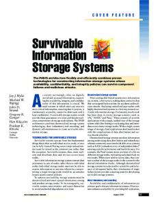
in all systems. Given its small physical size, high performance, non-volatility, and blocklevel data access, we examined using MEMS as another layer in the storage hierarchy to mask relatively large disk access latencies. We show that hybrid MEMS/disk systems can be nearly as fast as MEMS and as large and cheap as disks. This approach is fundamentally different from the HP MEMS/disk arrays [Uysal et al. 2003], where one copy of duplicate data in RAID 1/0 is stored in MEMS and requests are serviced by the most suitable devices based on access patterns. Among other things, the HP approach requires as much MEMS storage as disk; ours requires significantly less. We explore two alternative MEMS/disk subsystem architectures that can improve performance under a variety of workloads: MEMS Write Buffer (MWB), which logs dirty data to MEMS before committing to disk, and MEMS Caching Disk (MCD), which uses MEMS as a fully associative, write-back cache for disk. We show that MCD can provide up to half of the performance of a significantly more expensive (or lower capacity) MEMS-only system. 2. MEMS-BASED STORAGE MEMS-based storage device are comprised of two main components: groups of probe tips called tip arrays that are used to access data on a movable, non-rotating media sled. In modern disk drives, data is accessed by means of an arm that seeks in one dimension above a rotating platter. In MEMS devices, the entire media sled is positioned in the x and y directions by electrostatic forces while the heads remain stationary. Unlike disk drives, MEMS devices can activate multiple tips at the same time. Data can then be striped across multiple tips, providing a considerable amount of parallelism. Power and heat considerations limit the number of probe tips that can be active simultaneously; it is estimated that 200 to 2000 probes will actually be active at once. Figure 1 illustrates the low level data layout of a MEMS storage device. The media sled is logically broken into non-overlapping tip regions, defined by the area that is accessible by a single tip, approximately 2500 by 2500 bits in size. The size of each tip region is limited by the maximum dimension of the sled movement. Each tip in the MEMS device can only read data in its own tip region. The smallest unit of data in a MEMS storage device is called a tip sector. Each tip sector, identified by the tuple hx, y,tipi, has its own servo information for positioning. The set of tip sectors accessible to simultaneously active tips with the same x coordinate is called a tip track, and the set of all bits (under all tips) with the same x coordinate is referred to as a cylinder. Also, a set of concurrently accessible tip sectors is grouped as a logical sector. For faster access, logical blocks can be striped across logical sectors. Table I summarizes the physical parameters of MEMS-based storage used in our research, based on the predicted characteristics of the second generation MEMS-based storage devices [Schlosser et al. 2000]. While our exact performance numbers depend upon the details of that specification, the techniques themselves do not. ACM Transactions on Storage, Vol. X, No. X, XX 2005.
4
·
Bo Hong et al. Area accessible to one probe tip
Cylinder
Servo info
Bits
Tip sector
Y Tip track Area accessible to one probe tip (tip region)
X
Fig. 1. Data layout on a MEMS device.
3. RELIABILITY OF MEMS-BASED STORAGE ENCLOSURES MEMS-based storage can replace disks in storage systems, especially in mobile computing and high-end systems where size and power or performance are important. In general, disks have much higher storage capacities than MEMS storage devices. For instance, disk capacities range from 18–300 GB for server disks and 20–80 GB for laptop disks [Hitachi Global Storage Technologies 2004; Seagate Technology, Inc. 2004], reported in August 2004. To base a storage system completely on MEMS-based storage, we need 10–100 times more MEMS devices and corresponding connection components to equal the capacity of disks. While a single MEMS device is expected to be more reliable than a disk, such a large number of MEMS storage components yields lower overall system reliability. 3.1 Reliable Storage Building Bricks—MEMS Storage Enclosures To address the system reliability problem, we believe that multiple MEMS devices should be integrated into a MEMS storage enclosure organized as RAID-5 and accessed with a unified interface. We choose RAID-5 as the data redundancy scheme because of its reliability, space efficiency, and wide acceptance. Like disks, MEMS enclosures can be used as the basic building brick in storage systems, providing reliable persistent storage. However, MEMS enclosures can contain several online spares, in addition to the data and parity devices, providing better reliability, durability, and economy than disk drives. Adding spares is feasible for MEMS enclosures thanks to the small physical size, low power consumption, and relatively low unit cost of MEMS storage. An enclosure controller can automatically detect device failures and begin data recovery to on-line spares immediately. This can improve MEMS enclosure reliability by reducing both the window of data vulnerability and the chance of human errors. The shorter device rebuild times of of MEMS devices, due to their higher bandwidth and lower capacity, further reduces the window of vulnerability. With multiple on-line spares, an enclosure can tolerate several device failures in the economic lifetime, increasing its durability and reducing its maintenance frequency and cost. A MEMS enclosure can notify the host system, the maintenance personnel and/or the end users through signals when it runs out of spares. For example, a red / amber / green LED combination might inform a laptop user of the state of the enclosure. The failing enclosure can either be replaced or replenished with new spares to increase its lifetime, as ACM Transactions on Storage, Vol. X, No. X, XX 2005.
·
ACM Transactions on Storage
5
1
Survival Rate R(t)
0.8
(Ν+1)λ
N/1 ρ1
N/0
µ
D/1
Νλ
(Ν+1)λ ρ0
DL D/0
0.6
0.4
Disk, 11.5 Yrs Disk, 23 Yrs No spare 1 spare 2 spares 3 spares 4 spares 5 spares
0.2
Νλ 0 0
1
2
3
4
5
Time (years)
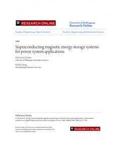
Fig. 2. Markov model for a MEMS storage enclosure. Fig. 3. Survival rate of MEMS storage enclosures without repairs in five years.
desired. There are two maintenance strategies: the preventive strategy repairs the enclosure when it runs out of spares and the mandatory strategy does so only when the enclosure operates in degraded RAID-5 mode without any spares. MEMS storage enclosures require little or no modification of disk-based storage management software. As disk replacement devices, MEMS enclosures provide a linear block address space and use the same interface as disks. The host operating systems need to understand the reliability statuses of MEMS enclosures and take actions accordingly. S.M.A.R.T. (Self-Monitoring Analysis and Reporting Technology) provides the same functionality for hard drives [Hitachi Global Storage Technologies 2004; Hughes et al. 2002; Seagate Technology, Inc. 2004]. 3.2 Reliability of MEMS Storage Enclosures MEMS storage enclosures are internally organized as RAID-5 with on-line spares. Researchers traditionally approximate the lifetimes of RAID-5 systems as exponential and use Mean Time To Failure (MTTF) to describe their reliability [Chen et al. 1994]. This approximation is accurate enough because the system component lifetimes are also modeled as exponential and failed components are replaced in time, i.e. the system is repairable. MEMS enclosures with repairs share similar reliability characteristics with RAID-5 systems and their lifetimes can also be modeled as exponential. Without failed device replacement, the lifetime of a MEMS enclosure has two stages, a reliable stage with spares and an unreliable stage without spares; it cannot be simply modeled as exponential. The enclosure with spares can be as reliable as RAID-5 systems with very short device rebuild times. It becomes unreliable after spares run out because any two successive device failures can result in data loss. Figure 2 shows the Markov model for a MEMS storage enclosure with N data and one parity devices and one dedicated spare. The spare device does not participate in request services during normal operations. The enclosure can be in three modes: normal (N), degraded (D), and data loss (DL). The numbers (0 or 1) in the figure indicate how many spares the enclosure still has. We assume that MEMS lifetimes, data recovery times to on-line spares, and system repair times are independent and exponential. The average MEMS lifetime and data recovery time are MTTFmems = 1/λ and MTTRmems = 1/µ; the mandatory and preventive system repair rates are ρ0 and ρ1 , respectively. These rates ACM Transactions on Storage, Vol. X, No. X, XX 2005.
6
·
Bo Hong et al.
are zero for enclosures without repair. 3.2.1 Reliability without Repairs. We first studied the reliability of MEMS storage enclosures without repairs, whose Markov model is that of Figure 2 with ρ0 = ρ1 = 0. We assume that data loss can be only caused by MEMS device failures. Researchers and engineers expect MEMS-based storage to be more reliable than disk because of its architectures, miniature structures, and manufacturing processes [Carley et al. 2000; Griffin et al. 2000b]. Unfortunately, there is as yet no data to back up this assumption. However, we know that Digital Micromirror Devices (DMD), a commercialized MEMS-based digital imaging technology, have Mean Time Between Failure (MTBF) of 650,000 hours (74 years) [Douglass 2003]. For simplicity, we suppose the average MEMS storage device lifetime, MTTFmems , to be 200,000 hours (23 years). For the purpose of comparison, we assume the lifetimes of commodity disks and “better” disks are exponentially distributed with means of 100,000 and 200,000 hours, respectively. We estimate the average data recovery time to on-line spares, MTTRmems , to be 15 minutes. The estimate is very conservative given the high bandwidth and limited capacity of MEMS: we assume less than 5% of device bandwidth devoted to data recovery. Suppose a MEMS enclosure contains 19 data, one parity, and k dedicated spares. Its user-visible capacity is 60 GB because each MEMS device can provide 3.2 GB of storage. While the exact reliability numbers depend upon these assumptions, the techniques themselves do not. Simple calculations reveal the MTTF of MEMS enclosures with zero to five spares to be 2.3, 3.5, 4.6, 5.8, 6.9, and 8.1 years, respectively, values which are surprisingly low. However, in their economic lifetimes, say 3–5 years, MEMS enclosures with several spares can be more reliable than disks with MTTF as high as 200,000 hours (23 years), even without replacement of failed MEMS devices. This is shown in Figure 3, which illustrates the survival rates of MEMS enclosures without repairs. The survival rate R(t) of an individual system is defined as the probability that the system survives for any lifetime t given that it is initially operational [Bhat and Miller 2002]: R(t) = Pr[lifetime > t | initially operational]. For example, the probability of data loss of a MEMS enclosure with five spares in the first three years is 1.75%, much better than 12.31% of a single disk with MTTF of 23 years. However, the enclosure becomes highly unreliable after it runs out of spares; the probabilities of data loss in such a device in one year is 21.06%. As mentioned above, the survival rates of MEMS enclosures do not follow exponential distributions. Instead, they follow Weibull-type distributions: enclosures achieve higher survival rates in the beginning but then rather suddenly fall below the survival rate of a disk, as shown in Figure 3. Thus, even though a MEMS enclosure might have a smaller MTTF, its survival rate for the first several years can be significantly better than that of a disk. Generally, economic lifetimes (3–5 years) are much smaller than component MTTF (> 10 years), which explains the seemingly paradoxical situation that enclosures with lower MTTF may be more reliable than disk drives. The unreliable stage of a MEMS enclosure can be quickly noticed by the system and then a repair can be scheduled in time. Note that MEMS enclosures are only the building bricks of storage systems and higher levels of redundancy may be provided in MEMSenclosure-based systems, as in disk-based systems. All of the data on an “unhealthy” ACM Transactions on Storage, Vol. X, No. X, XX 2005.
·
ACM Transactions on Storage 100000
1 No Spare 1 Spare - preventive 2 Spares - preventive 3 Spares - preventive 1 Spare - mandatory 2 Spares - mandatory 3 Spares - mandatory
0.8
Probability
10000
MTTF (years)
7
1000
100
10
0.6
0.4
Disk, 23 Yrs No failure 1 failure 2 failures 4 failures 6 failures 8 failures 10 failures
0.2
1
0 0
10
20
30
40
50
60
70
80
Replacement Time (days)
Fig. 4. MTTF of MEMS storage enclosures under different maintenance strategies and repair rates.
90
0
1
2
3
4
5
Time (years)
Fig. 5. Probabilities that a MEMS storage enclosure has up to k failures during (0, t].
enclosure can be replicated to an on-line spare enclosure within one hour, assuming an average 17 MB/s bandwidth consumption, which is only 1% of the aggregate bandwidth of the MEMS enclosure. 3.2.2 Reliability with Repairs. There are two maintenance strategies for MEMS enclosures, preventive replacement and mandatory replacement, as discussed in Section 3.1 and modeled in Figure 2. Preventive replacement can significantly improve the reliability of MEMS enclosures because they can still tolerate one more failure during the repair time, typically in days or weeks, thanks to their internal RAID-5 organization. Mandatory replacement postpones enclosure repairs as late as possible. This can reduce the maintenance frequency during the enclosure lifetime, but exposes users to greater risk of data loss or unavailability. Figure 4 shows Mean Time To Failure (MTTF) of MEMS storage enclosures with different numbers of spares under different maintenance strategies and repair rates (as represented as ρ0 and ρ1 in Figure 2), ranging from one day to three months. We set ρ0 = ρ1 > 0 for preventive replacement and ρ0 > 0 and ρ1 = 0 for mandatory replacement. As can be seen, on-line spares with preventive replacement dramatically increase the MTTF of MEMS enclosures, about one to two orders of magnitudes higher than MTTF of enclosures without on-line spares, under the same repair rate. Without preventive replacement, the reliability improvement by on-line spares is less impressive. Given the same repair rate, preventive replacement can provide higher reliability than mandatory replacement. In other words, preventive replacement requires less urgent maintenance than mandatory replacement to achieve the same level of reliability. 3.2.3 Reliability of Distributed Sparing. Spare storage in MEMS enclosures can also be organized in a distributed fashion. In distributed sparing [Menon and Mattson 1992], client data, parity data, and spare space are evenly distributed on all of the devices in the enclosure. This technique can provide better performance than dedicated sparing in the normal and data reconstruction modes [Menon and Mattson 1992; Thomasian and Menon 1997]. Distributed sparing can reduce data reconstruction time because it needs to reconstruct less data than dedicated sparing and its data reconstruction can proceed in parallel from and to all devices, avoiding the serialized reconstruction problem in dedicated sparing. However, distributed sparing utilizes more devices, which may undermine the ACM Transactions on Storage, Vol. X, No. X, XX 2005.
8
·
Bo Hong et al.
overall enclosure reliability. We found that distributed sparing and dedicated sparing generally provide comparable or almost identical reliability for the MEMS enclosure configurations under examination because the typical average device replacement time is in days or weeks and the average data reconstruction time to on-line spares is in minutes. Thus, the risk of data loss during the data reconstruction time is almost neglectable compared to the risk during the enclosure repair time. 3.3 Durability of MEMS Storage Enclosures In MEMS storage enclosures, failed devices tend to be replaced as late as possible or even not replaced during the enclosure economic lifetimes (typically 3–5 years) to minimize maintenance costs and human interferences. We therefore examine the survivability of MEMS enclosures with different numbers of on-line spares under mandatory and preventive maintenance policies in the first one, three, or five years. We again consider a MEMS enclosure with one parity and 19 data devices and k dedicated spares. Because reconstructing a failed MEMS device in a MEMS enclosure takes a very short time, we assume for simplicity that data reconstruction to on-line spares completes instantaneously once one device fails. Let pn (t) be the probability that exactly n MEMS devices in the enclosure have failed during the period of (0, t] [Bhat and Miller 2002]. The probability that a MEMS enclosure confronts up to k failures during the period of (0, t] is Pk (t) =
n=k X
pn (t)
(1)
n=0
=
n=k X n=0
e−λN t (λN t)n
1 , n!
where λN = N λ, N is the number of data and parity devices in the enclosure and 1/λ is MTTF of MEMS devices. In other words, the enclosure can survive after time t with the probability of Pk (t) as long as it can tolerate up to k failures. A MEMS enclosure with k spares can tolerate up to k + 1 failures without repairs in its lifetime. With m repairs (m ≥ 1), the enclosure can tolerate up to k × (m + 1) failures under preventive replacement and (k + 1) × (m + 1) failures under mandatory replacement before the (m+1)st repair is scheduled. Here we assume enclosure repairs can be completed instantaneously because we are interested in how many times an enclosure has to be repaired during its economic lifetime, instead of its reliability. Figure 5 illustrates the probabilities that up to x failures occur in a MEMS enclosure during (0, t]. The probabilities that a disk with MTTF of 23 years can survive for more than one, three, and five years are 95.7%, 87.7%, and 80.3%, respectively. A MEMS enclosure with two spares has a 98.8% probability of surviving for one year without repair. The probability that an enclosure with five spares can survive for five years without repair is 84.6%. The probability that an enclosure with three spares under preventive replacement requires more than one repair during five years is 15.4%. The probability for the same enclosure under mandatory replacement is only 3.5%. Clearly, preventive replacement trades more maintenance services for higher reliability, compared to mandatory replacement. Figure 5 is almost identical to Figure 3 because the average data recovery time to on-line ACM Transactions on Storage, Vol. X, No. X, XX 2005.
ACM Transactions on Storage
·
9
spares is very short in reality. The assumption of instantaneous data recovery in Figure 5 is also quite accurate for MEMS enclosures without repairs, which allows us to quickly approximate, using Equation 1, the survival rates of MEMS enclosures without repairs without solving messy ordinary differential equations. As building bricks of storage systems, MEMS storage enclosures with on-line spares have higher probability than disks to survive their economic lifetimes. This makes MEMS enclosures well suited for mobile applications and I/O intensive high-end applications, where size, power, and performance may be important. 4. USING MEMS-BASED STORAGE IN THE STORAGE HIERARCHY Although MEMS-based storage is superior to disk in many respects, including performance and power consumption, disk retains its advantage over MEMS in terms of capacity per device and cost per byte. Thus, while MEMS may dominate in certain applications, we expect disk to continue to play an important role in secondary storage for the foreseeable future. We now turn our attention to improving storage performance by adding MEMSbased storage as an additional layer between RAM and disk in the storage hierarchy. We show that MEMS can mask the relatively large disk access latencies so that the hybrid MEMS/disk systems can be nearly as fast as MEMS and as large and cheap as disks. 4.1 Hybrid MEMS/Disk Storage Subsystem Architectures From the operating system point of view our MEMS/disk hybrid storage system will appear to be nothing more than a fast disk. We envision the MEMS device residing either on the disk controller or packaged with the disk itself. In either case, the relatively small amount of MEMS storage will have a correspondingly small impact on the system cost, but can provide significant improvements in storage subsystem performance. MEMS-based storage has been used to improve performance and cost/performance in the HP hybrid MEMS/disk RAID systems [Uysal et al. 2003]. In this system, half of the disks in RAID 1/0 were replaced with MEMS devices, storing one copy of the replicated data in MEMS. Based on data access patterns, requests are serviced by the most suitable devices to leverage fast access of MEMS and high bandwidth of disk. Our work differs in three important respects. First, we wish to provide a single “virtual” storage device with the performance of MEMS and the cost and capacity of disk. Such a device can be easily employed in every kind of storage system, not just in RAID 1/0. Second, we use MEMS as another layer in the storage hierarchy, instead of as a disk replacement. Third, our system requires less MEMS than disk, providing a better overall cost/performance ratio. Ultimately, we believe that our work complements the HP architecture and the two techniques could even be used in conjunction. 4.1.1 Using MEMS as a Disk Write Buffer. The small write problem plagues storage system performance [Chen et al. 1994; Rosenblum and Ousterhout 1992; Ruemmler and Wilkes 1993b]. In our MEMS Write Buffer (MWB) architecture, a fast MEMS device acts as a large non-volatile write buffer for the disk. All write requests are appended to MEMS as logs and reads to recently-written data are fulfilled by MEMS. A data lookup table maintains data mapping information from MEMS to disk. For crash recover, this is also duplicated in the MEMS log headers. Figure 6 shows the MEMS Write Buffer architecture. A non-volatile log buffer stands between MEMS and disk to match transfer bandwidths of MEMS and disk. ACM Transactions on Storage, Vol. X, No. X, XX 2005.
10
·
Bo Hong et al. Controller
Controller
Cache
Cache
log 1
segment 1
log 2
segment 2
MEMS log n
Disk Log Buffer
Data Flow
MEMS segment n
Control Flow
Fig. 6. MEMS Write Buffer.
Disk Segment Buffer
Data Flow
Control Flow
Fig. 7. MEMS Caching Disk.
MEMS logs are flushed to disk in background when the MEMS space is heavily utilized. MWB organizes MEMS logs as a circular FIFO queue so the earliest-written logs are cleaned first. During clean operations, MWB generates disk write requests, which can be further concatenated into larger requests if possible, according to the validity and disk locations of data in one or more MEMS logs. MWB can significantly reduce disk traffic because MEMS is large enough to exploit spatial localities in data accesses and eliminate unnecessary overwrites. MWB stages bursty write activities and amortizes them to disk idle periods to better utilize disk bandwidth. In contrast to RAM-based buffering, the non-volatility of MEMS ensures that no data is lost in the event of a power failure. 4.1.2 MEMS Caching Disk. MEMS Write Buffer is designed to optimize write intensive workloads. As such it provides only marginal performance improvement for reads. MEMS Caching Disk (MCD) addresses this problem by using MEMS as a fully associative, write-back cache for the disk. In MCD all requests are serviced by MEMS. The disk space is partitioned into segments, which are mapped to MEMS segments when necessary. Data exchanges between MEMS and disk are in segments. As in MWB, data mapping information from MEMS to disk is maintained by a table that is duplicated in the MEMS segment headers. Figure 7 shows the MEMS Caching Disk architecture. The non-volatile speeding-matching segment buffer provides optimization opportunities for MCD, which will be described later. It is well-known that data accesses tend to have both temporal and spatial localities [Roselli et al. 2000; Ruemmler and Wilkes 1993b] and the amount of data accessed during a period (the working set) tends to be relatively small compared to the underlying storage capacity [Ruemmler and Wilkes 1993a]. Thanks to the relatively large capacity of MEMS storage devices, MEMS Caching Disk can hold a significant portion of the working set and thus effectively reduce disk traffic. Exchanging data between MEMS and disk in large segments can better utilize disk bandwidth and implicitly prefetch sequentially accessed data. All of these improve system performance. The performance of MCD can further be improved by reducing unnecessary steps in the critical data paths and relaxing the data validity requirement on MEMS, which result in three techniques described below: ACM Transactions on Storage, Vol. X, No. X, XX 2005.
ACM Transactions on Storage
·
11
—Shortcut: MCD buffers data in the speed-matching segment buffer when it reads data from the disk. Pending requests can be serviced directly from the buffer without waiting for data being written to MEMS. This technique is called Shortcut. Physically, Shortcut adds a data path between the segment buffer and the controller. By removing an unnecessary step from the critical data path, Shortcut can improve response times for both reads and writes without extra overhead. —Immediate Report: MCD writes evicted dirty MEMS segments to disk before it frees them for new requests. However, MCD can safely free MEMS segments as soon as dirty data is destaged to the non-volatile segment buffer, reducing the delay associated with reclaiming dirty segments. This technique is called Immediate Report. —Partial Write: MCD reads disk segments to MEMS before it services write requests smaller than the MCD segment size. By carefully tracking the validity of each block in MEMS segments, MCD can write partial segments without reading them from disk first, leaving some MEMS blocks undefined. This technique is called Partial Write. Partial Write which requires a block bit map in each MEMS segment header to keep track of block validity. It can achieve performance similar to that of MEMS Write Buffer. 4.2 Experimental Analyses We implemented MEMS Write Buffer and MEMS Caching Disk in DiskSim [Ganger et al. 1999] to evaluate their performance. The default MEMS physical parameters is shown in Table I. We used the Quantum Atlas 10K disk drive (8.6 GB, 10,025 RPM) as the base disk model, whose average seek times of read/write are 5.7/6.19 ms. We changed its maximal throughput to 50 MB/s to better evaluate system performance with modern disks. We used workloads traced from different systems to exercise the simulator. TPC-D and TPC-C are two TPC benchmark workloads, representing workloads for on-line decision supports and on-line transaction processing applications, respectively. Cello and hplajw are a news server and a user workloads from Hewlett-Packard Laboratories, respectively. Because the capacity of Atlas 10K is 8.6 GB, we set the default MEMS size to be 256 MB, which corresponds to 3% of the disk capacity. The controller has 4 MB cache by default and employs the write-back policy. The non-volatile speed-matching buffer between MEMS and disk is 2 MB. 4.2.1 Comparison of Improvement Techniques in MEMS Caching Disk. In general, Immediate Report can improve response times for write-dominant workloads, such as TPC-C and cello, by leveraging asynchronous disk writes. Partial Write can effectively reduce read traffic from disk to MEMS when the workload is dominated by writes and their sizes are often smaller than the MEMS segment size, as in cello: 52% of its write requests are smaller than the 8 KB segment size. The performance improvement afforded by Shortcut depends heavily on the amount of disk read traffic, as in TPC-D) and cello. Cello also has significant internal read traffic due to partial MEMS segment writes. The overall performance improvement by these techniques ranges from 14% to 45%. 4.2.2 Comparison of Segment Replacement Policy. Because disk access times are in milliseconds, MEMS Caching Disk can potentially take advantage of more effective and computationally-intensive cache replacement algorithms such as Least Frequent Used with Dynamic Aging (LFUDA) [Arlitt et al. 1999] or Adaptive Replacement Caching (ARC) [Megiddo and Modha 2003]. LFUDA considers both frequency and recency in data acACM Transactions on Storage, Vol. X, No. X, XX 2005.
3.82
4
3.24 3 2.42
2.42 1.97
2
1.08
1 0 Disk
MWB
MCD NONE
MCD ALL
DISK−RAM
5 4 3 2 1
Unbounded queueing delay
5
Unbounded queueing delay
Response Time Average (ms)
Bo Hong et al. Response Time Average (ms)
·
12
Disk
MWB
20
10 2
1.88
0 Disk
MWB
MCD NONE
MCD ALL
DISK−RAM
0.64 MEMS
(c) Cello Trace
Response Time Average (ms)
Response Time Average (ms)
30
3.64
2.35
0.93
MCD NONE
MCD ALL
DISK--RAM MEMS
(b) TPC-C Trace
37.68
3.13
3.09
0
MEMS
(a) TPC-D Trace 40
3.79
5 4
3.61
3 2
2 1
0.76
0.65 0.3
0.32
DISK−RAM
MEMS
0 Disk
MWB
MCD NONE
MCD ALL
(d) Hplajw Trace
Fig. 8. Overall performance comparison cesses by using a dynamic aging factor, which is initialized to be zero and updated to be the priority of the most recently evicted object. Whenever an object is accessed, its priority is increased by the current aging factor plus one. LFUDA evicts the object with the least priority when necessary. We compared the performance of two segment replacement policies in MCD: LRU and LFUDA. In general LRU performed as well as and, in many cases, better than LFUDA. Based on its simplicity and good performance, we chose LRU to be the default segment replacement policy in any further analysis. 4.2.3 Performance Impacts of MEMS Sizes and Segment Sizes. The performance of MCD is affected by two factors: the segment size and the MEMS cache utilization. Large segments increase disk bandwidth utilization and facilitate prefetching, which favors workloads with many large sequential reads, such as TPC-D. However, segments much larger than the average request size increase data transfer time and may reduce MEMS cache utilization if the prefetched data is useless. Large segments also decrease the number of buffer segments for a fixed buffer size, which can have a negative impact on the effectiveness of Shortcut and Immediate Report. These effects can be seen in the TPC-C and cello workloads, which are dominated by small and random requests. 4.3 Performance Evaluation We evaluated the overall performance of MEMS Write Buffer (MWB) and MEMS Caching Disk (MCD). The default MEMS size is 256 MB. We either enabled all MCD optimization techniques (MCD ALL) or not (MCD NONE). The segment sizes of MCD are 256 KB, 8 KB, 8 KB, and 64 KB for the TPC-D, TPC-C, cello, and hplajw workloads, respectively. The MWB log size is 128 KB. We used three performance baselines to calibrate these architectures: the average reACM Transactions on Storage, Vol. X, No. X, XX 2005.
ACM Transactions on Storage
·
13
sponse times of a disk (DISK), of MEMS devices (MEMS), and using a disk with 256 MB RAM cache (DISK-RAM). By employing a controller cache with the same size of MEMS, we approximated the system performance of using the same amount of non-volatile RAM (NVRAM) instead of MEMS. Figure 8(a)–8(d) show the average response times of different architectures and configurations under the TPC-D, TPC-C, cello, and hplajw workloads, respectively. In general, using MEMS as disk replacement achieves the best performance in TPC-D, TPC-C, and cello thanks to its superior performance. DISK-RAM only performs slightly better than MEMS in hplajw because the majority of its working set can be held in nearly-zero-latency RAM. DISK-RAM performs better than MCD by various degrees (6–64%), dependent upon the workload characteristics and working set sizes. In both MCD and DISK-RAM, the large disk access latency is still a dominant factor. DISK and MWB have the same performance in TPC-D (Figure 8(a)) because TPC-D has no writes. DISK has better performance than MCD. In such a highly sequential workload with large requests, the disk positioning time is not a dominant factor in request response times, and disk bandwidth can be fully utilized. LRU typically performs poorly under such streaming workloads, so MEMS cache is very inefficient. Instead, MCD adds one extra step into the data path, which can decrease system performance by 25%. DISK-RAM only has moderate performance gain due to the same reason. DISK cannot support the randomly-accessed TPC-C workload, as shown in Figure 8(b), because the TPC-C trace was gathered from an array with three disks. Although write activities are substantial (48%) in TPC-C, MWB cannot support it either. Unlike MCD, which does update-in-place, MWB appends new dirty data to logs, which results in lower MEMS space utilization, and thus higher disk traffic in such a workload with frequent record updates. MCD significantly reduces disk traffic by holding a large fraction of the TPC-C working set. Both MCD NONE and MCD All can achieve respectable response times of 3.79 ms and 3.09 ms, respectively. Cello is a write intensive and non-sequential workload. MWB dramatically improves the average response time of DISK by a factor of 14 (Figure 8(c)) because it can significantly reduce disk traffic and increase disk bandwidth utilization by staging dirty data on MEMS and writing it back to disk in large extents. In cello, 52% of write requests are smaller than the 8 KB MCD segment size. By data logging, MWB also avoids disk read traffic generated by MCD NONE, which must fetch corresponding disk segments to MEMS. This problem is addressed by the technique of Partial Write. Generally MCD has better MEMS space utilization than MWB because it does update-in-place. Thus MCD can hold a larger portion of the working set of cello, further reducing traffic to disk. For all these reasons, MCD ALL performs better than MWB by 57%. Hplajw is a read-intensive and sequential workload. Thus, MWB can not improve system performance as much as MCD. The working set of hplajw is relatively small so MCD can hold a large portion of it and achieves response times less than 1 ms. Although MCD degrades system performance under TPC-D and its performance is sensitive to the segment size under TPC-D and TPC-C, system performance tuning for such specific workloads can be easy because the workload characteristics are typically known in advance. Controllers can also trivially bypass MEMS under workloads similar to TPCD, where the disk bandwidth is the dominant performance factor. In general-purpose file system workloads, such as cello and hplajw, MCD performs well and robustly. ACM Transactions on Storage, Vol. X, No. X, XX 2005.
·
Bo Hong et al. Performance Improvment (%)
14
80 40 0 - 40
Cello Hplajw TPC-C TPC-D
- 80 - 120 10X
8X
6X
4X
2X
1X
Cost Ratio (NVRAM/MEMS)
Fig. 9.
Cost/performance analyses
4.4 Cost/Performance Analyses DISK-RAM has better performance than MCD when the sizes of NVRAM and MEMS are the same. However, MEMS is expected to be much cheaper than NVRAM. Figure 9 compares the performance of DISK-RAM and MCD, which are equipped with the equivalent dollar amounts of MEMS and NVRAM as disk cache. We varied the NVRAM/MEMS cost ratios from 1 to 10. The comparison baseline is the average response time of MCD. Using MEMS instead of NVRAM as disk cache can achieve better performance in TPC-C, cello, and hplajw unless NVRAM is as cheap as MEMS. The disk access latency is 4–5 orders of magnitude and 10 times higher than the latencies of NVRAM and MEMS, respectively. Thus, cache hit ratio, which determines the fraction of requests requiring disk access, is the dominant performance factor. With cheaper prices and thus larger capacities, MEMS can hold a larger fraction of the working set than NVRAM, resulting in higher cache hit ratios and better performance. MCD does not work well under TPC-D and has consistently worse performance than DISK-RAM. 5. RELATED WORK MEMS-based storage is an alternative secondary storage technology currently being developed. Besides CMU [Carley et al. 2000], IBM has developed a prototype device, called Millipede [Vettiger et al. 2000] that, unlike the CMU design, writes data by moving probe tips in the z direction and making tiny physical marks on the media, as opposed to magnetic recording used in the CMU design. Additional hardware research is also being done at Hewlett-Packard Laboratories [Toigo 2000]. Recently, there has been interest in modeling MEMS storage device behaviors [Griffin et al. 2000a; Madhyastha and Yang 2001]. Parameterized MEMS performance prediction models [Dramaliev and Madhyastha 2003; Sivan-Zimet and Madhyastha 2002] were also proposed to narrow the design space of MEMS-based storage. Schlosser and Ganger [Schlosser and Ganger 2004] suggested that roles and policies proposed for MEMS-based storage should be examined under two objective tests, specificity and merit, focusing on the use of MEMS-specific features and potential performance benefits, respectively. By comparing performance of MEMS devices and hypothetical “super” disks, they concluded that MEMS storage devices are much like disks, except for their efficient accesses for two-dimensional data structures. Our research illustrates that significant benefit can be obtained on system reliability and performance by leveraging the high-level, general properties of MEMS-based storage, such as small physical size, fast access, high throughput, and low unit cost. ACM Transactions on Storage, Vol. X, No. X, XX 2005.
ACM Transactions on Storage
·
15
5.1 Reliability of Storage Subsystems RAID [Chen et al. 1994] have been used for many years to improve both system reliability and performance. Menon, Mattson and Thomasian [Menon and Mattson 1992; Thomasian and Menon 1997] evaluated the performance of dedicated sparing [Dunphy et al. 1990], distributed sparing [Menon and Mattson 1992], and parity sparing [Reddy and Banerjee 1991] under the normal and data recovery modes of RAID systems. Muntz and Lui [Muntz and Lui 1990] proposed that a disk array of n disks be declustered by grouping the blocks in the disk array into reliability sets of size g and analyzed its performance under failure recovery. 5.2 Storage Hierarchy Using MEMS-based storage to improve storage system performance has been studied by several researchers. Simply using MEMS storage as a disk replacement can improve overall application run-times by 1.8–4.8 and I/O response times by 4–110; using MEMS as a non-volatile disk cache can improve I/O response times by 3.5 [Griffin et al. 2000b; Schlosser et al. 2000]. Uysal et al. [Uysal et al. 2003] proposed several MEMS/disk array architectures, where one copy of replicate data is stored in MEMS storage and based on access patterns requests are serviced by the most suitable devices to leverage fast accesses of MEMS and high bandwidths of disks. These hybrid storage architectures can achieve most of the performance benefits by MEMS arrays and their cost/performance ratios are better than disk arrays by 4–26. The small write problem has been intensively studied. Write cache, typically nonvolatile RAM (NVRAM), can substantially reduce disk write traffic and the perceived write delays [Ruemmler and Wilkes 1993b; Solworth and Orji 1990]. However, the high cost of NVRAM limits the amount used, resulting in low hit ratios in high-end disk arrays [Wong and Wilkes 2002]. Disk Caching Disk (DCD) [Hu and Yang 1996], which is architecturally similar to our MEMS Write Buffer, uses a small log disk to cache writes. LFS [Rosenblum and Ousterhout 1992] employs large memory buffers to collect small dirty data and write them to disk in large sequential requests. 6. FUTURE WORK MEMS storage enclosures without repairs exhibit unconventional non-exponential lifetime distributions. Storage systems based on such enclosures would exhibit reliability characteristics quite different from those of disks, whose lifetimes are typically regarded as exponential. The optional preventive repair policy makes it more difficult to estimate overall system reliability. In deciding upon a particular architecture, it is also necessary to understand the cost trade-off between system maintenance and investment on spare devices. This question is outside the scope of this paper. The performance of MEMS Caching Disk is sensitive, to various degrees, to its segment size and workload characteristics. It is possible for MCD to maintain multiple “virtual” segment managers, each using a different segment size, dynamically choosing the best one for a given data request. This technique is similar to Adaptive Caching Using Multiple Experts (ACME) [Ari et al. 2002]. MCD cannot improve system performance under highly-sequential streaming workloads, such as TPC-D. However, we can identify streaming workloads at the controller level and bypass MEMS to minimize its impact on system performance. Techniques that ACM Transactions on Storage, Vol. X, No. X, XX 2005.
16
·
Bo Hong et al.
can automatically identify workloads characteristics are desirable. 7. CONCLUSIONS As an emerging secondary storage technology, MEMS-based storage promises high storage density, high bandwidth, low access latency, low power consumption, small form factor, and low entry cost. MEMS storage devices can be used to either complement disks in some systems or replace them completely in other systems. Storage systems based completely on MEMS-based storage generally require many more MEMS devices than disks to meet their capacity requirements. To meet or exceed the reliability of disk drives, we organize numerous MEMS devices into MEMS storage enclosures, which serve as reliable storage building bricks in the systems. Our results show that adding a few on-line spares into these enclosures can make them much more reliable than traditional disks. Replacing disks with MEMS devices completely can be unnecessary for many applications which exhibit data access locality. We have shown that using a relatively small amount of MEMS as a write buffer or a cache for a disk can mask the relatively large disk access latencies. In particular, using MEMS as a disk cache can achieve significant performance improvement under a variety of workloads, approaching that of a pure MEMS storage enclosure, at much lower relative cost. ACKNOWLEDGMENTS
We are grateful to Greg Ganger, David Nagle, and the Parallel Data Laboratory at Carnegie Mellon for their help in our research. We also thank John Wilkes of Hewlett-Packard Laboratories and Yuanyuan Zhou of the University of Illinois for providing us with traces. We thank Ethan L. Miller, Ismail Ari, and other SSRC members for their support. This research is supported by the National Science Foundation under grant number CCR-0073509 and the Institute for Scientific Computation Research at Lawrence Livermore National Laboratory under grant number SC-20010378. Thomas Schwarz is supported in part by an SCU-internal IBM research grant. Additional support for the Storage Systems Research Center was provided by Engenio, Hewlett-Packard Laboratories, Hitachi Global Storage Technologies, IBM Research, Intel, Microsoft Research, Network Appliance, and Veritas. REFERENCES A RI , I., A MER , A., G RAMACY, R., M ILLER , E. L., B RANDT, S. A., AND L ONG , D. D. E. 2002. ACME: adaptive caching using multiple experts. In Proceedings in Informatics. Vol. 14. Carleton Scientific, Paris, France, 143–158. A RLITT, M., C HERKASOVA , L., D ILLEY, J., F RIEDRICH , R., AND J IN , T. 1999. Evaluating content management techniques for web proxy caches. In Proceedings of the 2nd Workshop on Internet Server Performance (WISP ’99). ACM Press, Atlanta, Georgia. B HAT, U. N. AND M ILLER , G. K. 2002. Elements of Applied Stochastic Processes, 3rd ed. John Wiley & Sons, Inc., New Jersey. C ARLEY, L., BAIN , J., F EDDER , G., G REVE , D., G UILLOU , D., L U , M., M UKHERJEE , T., S ANTHANAM , S., A BELMANN , L., AND M IN , S. 2000. Single-chip computers with microelectromechanical systems-based magnetic memory. Journal of Applied Physics 87, 9 (May), 6680–6685. C HEN , P. M., L EE , E. K., G IBSON , G. A., K ATZ , R. H., AND PATTERSON , D. A. 1994. RAID: Highperformance, reliable secondary storage. ACM Computing Surveys 26, 2 (June), 145–185. ACM Transactions on Storage, Vol. X, No. X, XX 2005.
ACM Transactions on Storage
·
17
D OUGLASS , M. R. 2003. DMD reliability: a MEMS success story. In Proceedings of SPIE. Vol. 4980. SPIE, San Jose, CA, 1–11. D RAMALIEV, I. AND M ADHYASTHA , T. 2003. Optimizing probe-based storage. In Proceedings of the Second USENIX Conference on File and Storage Technologies (FAST). USENIX Association, San Francisco, CA, 103–114. D UNPHY, R. H., J R ., WALSH , R., AND B OWERS , J. H. 1990. Disk drive memory. United States Patent 4,914,656. G ANGER , G. R., W ORTHINGTON , B. L., AND PATT, Y. N. 1999. The DiskSim simulation environment version 2.0 reference manual. Tech. rep., Carnegie Mellon University / University of Michigan. Dec. G RIFFIN , J. L., S CHLOSSER , S. W., G ANGER , G. R., AND N AGLE , D. F. 2000a. Modeling and performance of MEMS-based storage devices. In Proceedings of the 2000 SIGMETRICS Conference on Measurement and Modeling of Computer Systems. ACM Press, Santa Clara, CA, 56–65. G RIFFIN , J. L., S CHLOSSER , S. W., G ANGER , G. R., AND N AGLE , D. F. 2000b. Operating system management of MEMS-based storage devices. In Proceedings of the 4th Symposium on Operating Systems Design and Implementation (OSDI). USENIX Association, San Diego, CA, 227–242. H ITACHI G LOBAL S TORAGE T ECHNOLOGIES . 2004. Hitachi Disc Product Datasheets. http://www.hgst.com/. H U , Y. AND YANG , Q. 1996. DCD—-Disk Caching Disk: A new approach for boosting I/O performance. In Proceedings of the 23rd Annual International Symposium on Computer Architecture. ACM Press, Philadelphia, PA, 169–178. H UGHES , G. F., M URRAY, J. F., K REUTZ -D ELGADO , K., AND E LKAN , C. 2002. Improved disk-drive failure warnings. IEEE Transactions on Reliability 51, 3, 350–357. M ADHYASTHA , T. AND YANG , K. P. 2001. Physical modeling of probe-based storage. In Proceedings of the 18th IEEE Symposium on Mass Storage Systems and Technologies. IEEE Computer Society Press, Monterey, CA, 207–224. M EGIDDO , N. AND M ODHA , D. S. 2003. ARC: A self-tuning, low overhead replacement cache. In Proceedings of the Second USENIX Conference on File and Storage Technologies (FAST). USENIX Association, San Francisco, CA, 115–130. M ENON , J. AND M ATTSON , D. 1992. Comparison of sparing alternatives for disk arrays. In Proceedings of the 19th International Symposium on Computer Architecture. ACM Press, Queensland, Australia, 318–329. M UNTZ , R. R. AND L UI , J. C. S. 1990. Performance analysis of disk arrays under failure. In Proceedings of the 16th Conference on Very Large Databases (VLDB). Morgan Kaufmann, Brisbane, Queensland, Australia, 162–173. R EDDY, A. L. N. AND BANERJEE , P. 1991. Gracefully degradable disk arrays. In Proceedings of the 21rd International Symposium on Fault-Tolerant Computing (FTCS ’91). IEEE Computer Society Press, Montreal, Canada, 401–408. ROSELLI , D., L ORCH , J., AND A NDERSON , T. 2000. A comparison of file system workloads. In Proceedings of the 2000 USENIX Annual Technical Conference. USENIX Association, San Diego, CA, 41–54. ROSENBLUM , M. AND O USTERHOUT, J. K. 1992. The design and implementation of a log-structured file system. ACM Transactions on Computer Systems 10, 1 (Feb.), 26–52. RUEMMLER , C. AND W ILKES , J. 1993a. A trace-driven analysis of disk working set sizes. Tech. Rep. HPLOSR-93-23, Hewlett-Packard Laboratories, Palo Alto. Apr. RUEMMLER , C. AND W ILKES , J. 1993b. Unix disk access patterns. In Proceedings of the Winter 1993 USENIX Technical Conference. USENIX Association, San Diego, CA, 405–420. S CHLOSSER , S. W. AND G ANGER , G. R. 2004. MEMS-based storage devices and standard disk interfaces: A square peg in a round hole? In Proceedings of the Third USENIX Conference on File and Storage Technologies (FAST). USENIX, USENIX Association, San Francisco, CA, 87–100. S CHLOSSER , S. W., G RIFFIN , J. L., N AGLE , D. F., AND G ANGER , G. R. 2000. Designing computer systems with MEMS-based storage. In Proceedings of the 9th International Conference on Architectural Support for Programming Languages and Operating Systems (ASPLOS). ACM Press, Cambridge, MA, 1–12. S EAGATE T ECHNOLOGY, I NC . 2004. Seagate Disc Product Datasheets. http://www.seagate.com/products/datasheet/. S IVAN -Z IMET, M. AND M ADHYASTHA , T. M. 2002. Workload based modeling of probe-based storage. In Proceedings of the 2002 SIGMETRICS Conference on Measurement and Modeling of Computer Systems. ACM Press, Marina Del Rey, CA, 256–257. ACM Transactions on Storage, Vol. X, No. X, XX 2005.
18
·
Bo Hong et al.
S OLWORTH , J. A. AND O RJI , C. U. 1990. Write-only disk caches. In Proceedings of the 1990 ACM SIGMOD International Conference on Management of Data, H. Garcia-Molina and H. V. Jagadish, Eds. ACM Press, Atlantic City, NJ, 123–132. T HOMASIAN , A. AND M ENON , J. 1997. RAID5 performance with distributed sparing. IEEE Transactions on Parallel and Distributed Systems 8, 6 (June), 640–657. T OIGO , J. W. 2000. Avoiding a data crunch – A decade away: Atomic resolution storage. Scientific American 282, 5 (May), 58–74. U YSAL , M., M ERCHANT, A., AND A LVAREZ , G. A. 2003. Using MEMS-based storage in disk arrays. In Proceedings of the Second USENIX Conference on File and Storage Technologies (FAST). USENIX Association, San Francisco, CA, 89–101. V ETTIGER , P., D ESPONT, M., D RECHSLER , U., U RIG , U., A BERLE , W., L UTWYCHE , M., ROTHUIZEN , H., S TUTZ , R., W IDMER , R., AND B INNIG , G. 2000. The “Millipede”—More than one thousand tips for future AFM data storage. IBM Journal of Research and Development 44, 3, 323–340. W ONG , T. M. AND W ILKES , J. 2002. My cache or yours? making storage more exclusive. In Proceedings of the 2002 USENIX Annual Technical Conference. USENIX Association, Monterey, CA, 161–175. Y U , H., A GRAWAL , D., AND A BBADI , A. E. 2003. Tabular placement of relational data on MEMS-based storage devices. In Proceedings of the 29th Conference on Very Large Databases (VLDB). Morgan Kaufmann, Berlin, German, 680–693.
Received December 2004; revised December 2004; accepted December 2004
ACM Transactions on Storage, Vol. X, No. X, XX 2005.