of commercial and scientific space missions in Russia, the. US, Europe, and ...... pulsion Conference The Electric Rocket Propulsion Society, Worthing- ton, OH ...
PHYSICS OF PLASMAS
VOLUME 8, NUMBER 4
APRIL 2001
Plasma oscillations in Hall thrusters E. Y. Choueiri Electric Propulsion and Plasma Dynamics Laboratory, Princeton University, Princeton, New Jersey 08540
共Received 27 September 2000; accepted 14 November 2000兲 The nature of oscillations in the 1 kHz–60 MHz frequency range that have been observed during operation of Hall thrusters is quantitatively discussed. Contours of various plasma parameters measured inside the accelerating channel of a typical Hall thruster are used to evaluate the various stability criteria and dispersion relations of oscillations that are suspected to occur. A band by band up-to-date overview of the oscillations is carried out with a description of their observed behavior and a discussion of their nature and dependencies through comparison of the calculated contours to reported observations. The discussion encompasses the excitation of low frequency azimuthal drift waves that can form a rotating spoke, axially propagating ‘‘transit-time’’ oscillations, azimuthal drift waves, ionization instability-type waves, and wave emission peculiar to weakly ionized inhomogeneous plasmas in crossed electric and magnetic fields. © 2001 American Institute of Physics. 关DOI: 10.1063/1.1354644兴
I. INTRODUCTION
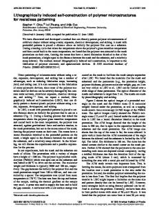
and other features of modern Hall thrusters, are also discussed in Refs. 6–9. A schematic of a Hall thruster of the SPT type 共i.e., extended channel兲 is shown in Fig. 1. Briefly, the underlying processes are as follows. The electrons from the cathode enter the chamber, and are subject to an azimuthal drift as a result of the crossed 共mainly radial兲 magnetic and axial electric fields. The electrons in the closed drift undergo ionizing collisions with the neutrals 共most typically xenon兲 injected through the anode. While the magnetic field is strong enough to lock the electrons in an azimuthal drift within the chamber, it is not strong enough to affect the trajectory of the ions which are essentially accelerated by the axial electric field. An axial electron flux equal to that of the ions reaches the anode due to a cross-field mobility that often exceeds classical values, and the same flux of electrons is available from the cathode to neutralize the exhausted ions. Quasineutrality is thus maintained throughout the chamber and exhaust beam, and consequently no space-charge limitation is imposed on the acceleration, allowing relatively high thrust densities compared to conventional electrostatic propulsion devices. Nominal operating conditions of a common flight module 共e.g., the Russian SPT-100兲 operating with xenon are 2–5 mg/s mass flow rate, 200–300 V applied voltage, yielding a plasma exhaust velocity of 16 000 m/s, and a thrust of 40–80 mN, at efficiencies of about 50%. Measured performance is reported in Refs. 10–12. Because of the stringent requirements of commercial spacecraft, which often require trouble-free thruster operation for more than 8000 hours, various aspects of Hall thruster performance can benefit from further improvements. These include efforts to lower beam divergence, characterize electromagnetic interference, lower erosion rate, lengthen lifetime, further raise the thrust efficiency and thrust to power ratio and scale these devices down or up in power. Also, more compact power processing units 共PPU兲 with specific masses around 5 kg/kW are sought to enhance the competitiveness of these thrusters. Aside from low mass, a major requirement of the PPU is its ability to handle or suppress
A. Background and motivation
Hall thrusters, also called closed drift thrusters 共CDT兲, are coaxial plasma accelerators for spacecraft propulsion that have been optimized in Russia during the past 30 years for high thrust efficiency 共near and above 50%). They are particularly suited for station keeping and orbit transfer missions where they offer substantial propellant mass savings over chemical thrusters. Since 1972, more than 110 Hall thrusters have been flown on Russian spacecraft, and more than 52 thrusters remain in operation.1 An increasing number of commercial and scientific space missions in Russia, the US, Europe, and Japan are planned with spacecraft using Hall thrusters. Some of the original work on the Hall thruster was conducted in the US in the early and mid-1960’s2–5 but interest in that accelerator was greatly diminished in favor of ion thrusters. Most of the work since then has been conducted in Russia until the early 1990’s when a resurgent interest in these devices in the US, Europe, and Japan brought about an increasingly strong revival in related research and development. The name ‘‘closed drift’’ refers to the azimuthal drift of electrons that is common to all variants of such thrusters. The two main modern variants are the stationary plasma thruster 共SPT兲 and the thruster with anode layer 共TAL兲. 关The stationary plasma thruster 共SPT兲 is sometimes referred to as magnetic layer thruster, or thruster with extended acceleration zone, to differentiate it from the anode layer thruster 共TAL兲, which is also operated in a stationary mode.兴 The former differs from the latter by its extended channel and the use of insulator chamber walls. Although the two have differentiating features in their operation and performance, they rely on the same basic principles for ionizing and accelerating the propellant. In the US, these principles were first correctly described and verified experimentally through the seminal work of Janes and Lowder 共1965兲.5 These principles, 1070-664X/2001/8(4)/1411/16/$18.00
1411
© 2001 American Institute of Physics
Downloaded 26 Mar 2001 to 128.112.35.99. Redistribution subject to AIP copyright, see http://ojps.aip.org/pop/popcr.jsp
1412
Phys. Plasmas, Vol. 8, No. 4, April 2001
E. Y. Choueiri
FIG. 1. Schematic of a Hall thruster with an extended insulator channel 共SPT兲 showing the external cathode, the internal anode, the radial magnetic field and typical particle trajectories.
oscillations in the total circuit. The interaction between the PPU and its load can be quite complex due to the ubiquitous presence of oscillations. As we shall see in the following sections, the Hall thruster plasma has a very rich and complex wave and noise characteristics over a wide frequency spectrum. The character of these oscillations range from narrowband and very coherent waves with well-defined propagation angles, to broadband turbulence. Aside from their role in PPU design, oscillations in Hall thrusters can play a role in the divergence of the ion beam and can even lead to an extinction of the discharge. More fundamentally, some of these oscillations play a direct role in setting the performance level and efficiency of these devices. Many of the oscillations are inherent to the ionization, particle diffusion, and acceleration processes of the device and can be considered as ‘‘natural’’ modes excited by the plasma to ‘‘self-regulate’’ the charged particle production and diffusion processes in order to adjust to a particular imposed operating mode. The earliest studies specifically addressing these oscillations are represented in Refs. 5, 9, 13, and 14. More recently, with the surge of interest in the US, Europe, and Japan, a number of Hall thruster oscillation studies15–26 have been carried out, many of which are ongoing. In an earlier conference paper27 we presented an overview of the observed oscillation modes along with a description of their nature and dependencies. In the present paper we present an updated
overview that accounts also for recent measurements and studies of Hall thruster oscillations. B. Organization
We start in Sec. II with a quantitative characterization of the plasma in a typical Hall thruster. We use contours of various plasma parameters measured inside the accelerating channel of the SPT as the starting point of our investigation and calculate the magnitude and spatial distribution of various associated natural and collision frequencies, characteristic lengths and velocities. This leads to a thorough characterization of the plasma in the channel under typical operation which paves the way for a quantitative band by band overview of the observed oscillations presented in Sec. III along with theoretical models for these oscillations and the associated stability criteria. The theoretical models are evaluated using the plasma characterization of the preceding section. II. HALL THRUSTER PLASMA CHARACTERIZATION
Before we proceed with the discussion of the various types of processes in the Hall thruster, and in order to render that discussion quantitative, we conduct a thorough and spatially resolved characterization of the plasma inside the channel. For all our subsequent calculations, we use as initial input, the contour plots measured inside the channel by Bishaev and Kim.28 Similar measurements were also reported by
Downloaded 26 Mar 2001 to 128.112.35.99. Redistribution subject to AIP copyright, see http://ojps.aip.org/pop/popcr.jsp
Phys. Plasmas, Vol. 8, No. 4, April 2001
Plasma oscillations in Hall thrusters
1413
FIG. 2. Axial profile of radial component of the magnetic field, B r normalized by its maximum value B r* 共with B r* ⫽180 G兲 as measured in Ref. 28.
FIG. 3. Total collision cross section for electrons in xenon from Ref. 30. a 0 is the Bohr radius.
Bishaev et al. in Ref. 29. These measurements were conducted in an SPT with a 10 cm diameter at a discharge volt˙ ⫽3 g/s of xenon, and a age U d ⫽200 V, a mass flow rate m discharge current of I d ⫽3 – 3.2 A. The authors reported29 that the dimensions of the probes used for these measurements were chosen to satisfy the requirements of the probe theories adopted for data reduction and that the measurement accuracy was checked using optical diagnostics. Other details concerning the experimental techniques can be found in these references.
m⫺3 . In reality, only the outer contour of the red region in that map was measured at that value. The lack of data inside that contour would artificially result in an infinite characteristic length for the density gradient in that region 共i.e., uniform density兲. This is to be kept in mind later when looking at maps calculated using the density gradients.
A. Input contours
First, the magnetic field, the radial variation of which may be neglected, was mapped axially with a Hall probe and is shown in Fig. 2. We digitized the contour data using a grid of 92 by 50 points with a spacing of 0.5 mm between points 共corresponding to the resolution of the measurements兲. The resulting matrices were then used along with an image processing algorithm that was developed specifically for this task, to generate 8-bit color raster images showing the magnitude and spatial distribution of the measured parameters. An image enhancement algorithm was then used to smooth the contours for better visualization. Consequently, in all the color raster plots in this paper, the details of any structure whose dimension is smaller than 0.5 mm cannot be taken as physical. The purple background surrounding each of the images correspond to regions where no experimental data were available. This is especially the case for many parameters near the walls. Also, the accuracy and reliability of the contours near the inlet or anode 共specifically for axial locations x⭐15 mm兲 are not good. Panels 共a兲–共e兲 of Fig. 8 below show the resulting contours for electron temperature, charged species density, floating potential, charge density production rate and xenon neutral gas density consecutively. The inlet and anode are on the left-hand side of the graphs, and the two parallel bottom and top gray lines represent the inner and outer insulator walls, respectively. The region of the electron density map that has the highest density 关Fig. 8共b兲兴 is shown to be uniform at 6⫻1017
B. Calculated plasma characteristics
The above-mentioned measurements are used to calculate various parameters of interest. This creates a thorough and spatially resolved characterization of the plasma. We calculate all the natural frequencies 共ion and electron cyclotron frequencies ci , ce ; ion and electron plasma frequencies pi , pe ; the lower hybrid frequency, lh 兲 many collision frequencies 共electron-neutral collision frequency e ; ion-neutral collision frequency i , Coulomb collision frequencies; frequency of ionization by electron impact, etc.兲. All the characteristic length scales corresponding to these frequencies are also calculated. We also calculate all the associated particle velocities: the electron thermal velocity v te ⫽(T e /m e ) 1/2; the Alfve´n velocity; the ion velocity and the electron azimuthal and axial drift velocities. In calculating the collision frequencies involving electrons at each grid point, we use experimentally measured cross sections for xenon with the full energy dependence and calculate the convolution integrals using a Maxwellian velocity distribution for the electrons. For instance, for the total electron-neutral collision frequency, e , we use
e ⫽n a
冕
F M 共 v 兲 Q e 共 v 兲v rel d v ,
共1兲
where v rel is the relative velocity between the two species and Q e is the total collision cross section obtained, for xenon, from the experimental measurements in Ref. 30 and shown in Fig. 3. When calculating the electron drift velocities we use the following standard expressions: u dex ⫽⫺D e⬜
共 n e kT e 兲 ⫺ e⬜ E x , n e x
Downloaded 26 Mar 2001 to 128.112.35.99. Redistribution subject to AIP copyright, see http://ojps.aip.org/pop/popcr.jsp
共2兲
1414
Phys. Plasmas, Vol. 8, No. 4, April 2001
E. Y. Choueiri
FIG. 4. Adopted rectangular coordinate system. The x axis is along the thruster axis 共i.e., along the applied electric field E x ) and the z axis is along the thruster radius 共i.e., along radial magnetic field B r ). The y axis therefore corresponds to the azimuthal dimension.
u dey ⫽⍀ e u dex ,
共3兲
where
e⬜ ⫽ D e⬜ ⫽
e 1⫹⍀ 2e
,
De 1⫹⍀ 2e
共4兲
共5兲
are related to the electron mobility and diffusion coefficients
e⫽
兩e兩 , m e e
共6兲
D e⫽
kT e m e e
共7兲
through the electron Hall parameter ⍀ e : ⍀ e⫽
ce . e
共8兲
For Eqs. 共2兲 and 共3兲 we treat each grid cell as imbedded in a rectangular coordinate system shown in Fig. 4, with the x-axis pointing downstream along the thruster axis 共i.e., along the applied electric field E x 兲 and the z-axis along the
thruster radius 共i.e., along radial magnetic field B r ). u dey therefore corresponds to the azimuthal electron drift velocity, which would be in the negative y direction. The application of this coordinate system to describe the entire channel carries the assumption of small channel curvature: h/RⰆ1, where h is the channel ‘‘height’’ and R its mean radius. All the above-mentioned parameters were calculated for each point of the grid. In order to illustrate the ordering of the magnitudes of these parameters, the parameter from each spatial matrix was spatially averaged between the cross sections at axial positions x 1 ⫽2.5 cm and x 2 ⫽4 cm and plotted in Figs. 5–7. These three plots show the magnitude ordering of the relevant frequencies, characteristic lengths, and velocities, respectively. 共The neutral gas temperature was assumed to be at the anode temperature of 1000 K.兲 In the characteristic length plot of Fig. 6, we also show the calculated characteristic lengths of the axial gradients of electron density, temperature, and magnetic field, which will be important for our oscillation analysis. In calculating the characteristic length of the electron density gradient we neglected the weight of the central region 关red spot in Fig. 8共b兲兴 which, as mentioned earlier, would have yielded very large lengths. The characteristic gradient length, L “ ␣ , of a parameter ␣ is given by L “␣⬅
冏 冏冏 冏 ␣ ln ␣ ⫽ ␣/x x
⫺1
,
共9兲
where x is the axial dimension. For further illustration, the spatial maps of the following parameters: electron-neutral total collision frequency e , ionization frequency ioniz , the axial electric field E x 共obtained by calculating the gradient of the applied potential兲, the ion velocity u i , the electron azimuthal drift velocity u dey , and the electron Hall parameter ⍀ e are shown in Figs. 8共f兲–9共e兲 consecutively. The total electron-neutral collision frequency e , shown in Fig. 8共f兲, was calculated using Eq. 共1兲 and its spatial dis-
FIG. 5. Magnitude ordering of relevant frequencies. 共Spatially averaged between the cross sections at axial positions x 1 ⫽2.5 cm and x 2 ⫽4 cm.兲
Downloaded 26 Mar 2001 to 128.112.35.99. Redistribution subject to AIP copyright, see http://ojps.aip.org/pop/popcr.jsp
Phys. Plasmas, Vol. 8, No. 4, April 2001
Plasma oscillations in Hall thrusters
1415
FIG. 6. Magnitude ordering of relevant lengths. 共Spatially averaged between the cross sections at axial positions x 1 ⫽2.5 cm and x 2 ⫽4 cm.兲
tribution, to a large extent, reflects the neutral xenon distribution in the channel shown in Fig. 8共e兲. This frequency, as we shall see later in Sec. III D 2, sets an upper limit for one type of oscillations. Its average between x 1 ⫽2.5 cm and x 2 ⫽4 cm is 1.53 MHz. The xenon ionization frequency ioniz by electron impact, shown in Fig. 9共a兲, is also important since it represents the characteristic oscillation of the ionization instability discussed later in Sec. III B. The axial electric field shown in Fig. 9共b兲 shows regions with values as high as 20 kV/m, which explains the electron heating seen in the same regions in the measured electron temperature plot of Fig. 8共a兲. The ion velocity map of Fig. 9共c兲 shows that the ions can reach velocities as high as 14 km/s inside the channel. It is interesting to note from that plot that the highest velocities are attained near the downstream end of the inner
insulator wall. This fact combined with the flow direction measurements in that region shown in Ref. 28, hint to the role played by ion sputtering in insulator erosion. The electron drift velocity in the azimuthal direction u dey , calculated with Eq. 共3兲 is shown in Fig. 9共d兲. Its average between x 1 ⫽2.5 cm and x 2 ⫽4 cm is 690 km/s. Again, the regions of substantial acceleration in that map corresponds to those of high electric field in Fig. 9共b兲. Finally, the electron Hall parameter ⍀ e is shown in Fig. 9共e兲. It is much larger than unity over the entire grid and averages about 286 between x 1 ⫽2.5 cm and x 2 ⫽4 cm. The corresponding average for the ion Hall parameter ⍀ i 共not shown here兲 is 0.15. This is characteristic of Hall thrusters whose design obeys the inequalities ⍀ i ⬍1Ⰶ⍀ i . This high value of the Hall parameter implies, through Eq. 共3兲, that the cross-field drift velocity
FIG. 7. Magnitude ordering of relevant velocities. 共Spatially averaged between the cross sections at axial positions x 1 ⫽2.5 cm and x 2 ⫽4 cm.兲
Downloaded 26 Mar 2001 to 128.112.35.99. Redistribution subject to AIP copyright, see http://ojps.aip.org/pop/popcr.jsp
1416
Phys. Plasmas, Vol. 8, No. 4, April 2001
E. Y. Choueiri
FIG. 8. 共Color兲 Contours of plasma parameters based on the measurements of Ref. 28. Averages between x 1 ⫽2.5 cm and x 2 ⫽4 cm are in parentheses. 共a兲 Electron temperature 共12.8 eV兲. 共b兲 Charged species density (3.3⫻1017 m⫺3 ). 共c兲 Floating potential 共73 V兲. 共d兲 Charge production rate (3.3⫻104 A/m3 ). 共e兲 Neutral xenon density (2⫻1019 m⫺3 ). 共f兲 Total electron-neutral collision frequency 共1.53 MHz兲.
towards the anode is, on the average, about 300 times smaller than the azimuthal drift velocity. This estimate is based on a classical treatment of cross-field mobility and diffusion. The real value of the axial electron current can be estimated by subtracting the measured ion current from the discharge current and is often much higher than the classical value given by Eq. 共2兲. Quite often, one must invoke nearwall collisional effects9,22,20 or plasma oscillations5,23,20,31 to explain the actual cross-field mobility and diffusion of the electrons when the magnetic field is high. With the above characterization, we have a detailed and
experimentally based picture of the plasma in the Hall thruster with which we can proceed to a quantitative study of the oscillations.
III. OVERVIEW OF OBSERVED OSCILLATIONS
Oscillations over a wide spectrum of frequencies have always been observed in the terminal characteristics of Halltype thrusters. During the 1970’s several experimental stud-
Downloaded 26 Mar 2001 to 128.112.35.99. Redistribution subject to AIP copyright, see http://ojps.aip.org/pop/popcr.jsp
Phys. Plasmas, Vol. 8, No. 4, April 2001
Plasma oscillations in Hall thrusters
1417
FIG. 9. 共Color兲 Results of calculations. Averages between x 1 ⫽2.5 cm and x 2 ⫽4 cm are in parentheses. 共a兲 Ionization frequency 共35.3 kHz兲. 共b兲 Axial electric field 共6.6 kV/m兲. 共c兲 Ion velocity 共9.3 km/s兲. 共d兲 Electron azimuthal drift velocity 共690 km/s兲. 共e兲 Electron Hall parameter 共286兲. 共f兲 Frequency of unstable waves according to Eq. 共22兲 for the first mode (k⫽1/r) with largely azimuthal propagation (k y ⫽10k x ). Purple⫽stable.
ies dedicated to the observation of oscillations and the measurements of their characteristics were conducted in Russia.9,13,14,32 The amplitude and frequencies of observed oscillations were found to be strongly dependent on operating conditions: 共1兲 共2兲 共3兲 共4兲
mass flow rate and propellant type; applied voltage; initial and time-evolving geometry; degree of contamination of the discharge chamber;
共5兲 cathode characteristics 共mass flow rate and location兲; 共6兲 PPU characteristics and configuration; 共7兲 and most strongly the magnetic field profile and magnitude. Furthermore, when spatially resolved probing of the oscillations was conducted32 inside the channel it was revealed that the oscillation spectra also depend on the axial location inside the channel. This multiparameter dependence renders the oscillation
Downloaded 26 Mar 2001 to 128.112.35.99. Redistribution subject to AIP copyright, see http://ojps.aip.org/pop/popcr.jsp
1418
Phys. Plasmas, Vol. 8, No. 4, April 2001
E. Y. Choueiri
TABLE I. Character of measured oscillation spectra as a function of the maximum value of the magnetic field ˙ ⫽4 mg/s, U d ⫽200 V and an SPT with a diameter B r* normalized by its optimal value, (B r* ) opt⯝170 G, for m of 9 cm operating with xenon. The numbers represent the relative importance of a given frequency band to the overall spectrum. The scale is 1 to 10 where 1 is the weak amplitude 共below the sensitivity of the diagnostics兲 and 10 is the dominant amplitude of the same order as the applied voltage. 0 means that the oscillations in that band were absent and NA denotes unavailable data. The digits are relative within a given band of frequencies and not across the bands. Based on experimental data and oscillograms from Refs. 9, 13, 14 and especially Ref. 32. Regime B r* /(B r* ) opt
I ⬍0.38
II 0.38–0.47
IIIa 0.47–0.6
IIIb 0.6–0.76
IV 0.76–1
V 1–1.35
VI 1.35⭐
1–20 kHz 20–60 kHz 共Azimuthal waves兲 20–100 kHz 70–500 kHz 2–5 MHz 共Azimuthal waves兲 0.5–10 MHz 10–400 MHz ⬎GHz
1
1
8
8
3
10
4
0
6
0
4
2
0
0
1 1
5 4
4 4
6 7
7 7
6 6
4 8
1
3
3
4
5
1
1
1 1 NA
3 3 NA
3 2 NA
4 3 NA
5 4 NA
5 5 NA
6 5 NA
picture too complex for straightforward description. However, the strong dependence on the magnetic field offers the opportunity to describe the oscillation spectra as a function of the maximum value of the magnetic field B r* 共usually reached a few millimeters upstream of the exit兲 with all other operating parameters 共geometry, mass flow rate, discharge voltage兲 held constant. 共This leaves the discharge current to be a unique function of the magnetic field.兲 This was attempted by Tilinin32 who conducted extensive measurements of the spectra in the range 10 kHz–400 MHz at four axial locations in the channel, and under a wide range of operating conditions. Tilinin identified six major regimes of operation, depending on the range of B r* , with each regime characterized by a general spectrum of oscillations and a range for the discharge current. A review of these measurements and others9,13,14 is summarized in Table I. In the following subsections we discuss these observations band by band. It is relevant to mention here that a survey of the Hall thruster oscillations can be made by varying the discharge voltage instead of varying the magnetic field. This was the route followed by the recent experimental characterization carried out by Chesta et al.16 and Gascon et al.18 Such surveys offer a different view of the dependencies of some of the modes described below. A. Bulk discharge oscillations in the 1–20 kHz band
1. Observed behavior
Oscillations in this frequency band are often referred to in the Russian literature as ‘‘loop,’’32 ‘‘circuit’’ or ‘‘contour’’26 oscillations. When B r* is increased to about half its optimal value 共Regime IIIa in Table I兲 these oscillations become prominent and their amplitude can reach 10% of the total voltage amplitude. For B r* /(B r* ) opt between 0.8 and 1, these oscillations are relatively damped. This regime of operation is called ‘‘optimal’’32 共Regime IV in Table I兲. The oscillations become violent as soon as B r* is increased a little
above its optimal value 共Regime V in Table I兲. Their amplitude can reach as high as 100% of that of the dc voltage, often causing the discharge to be extinguished. Since at B r* ⫽(B r* ) opt the ratio of the ion current at the exit to the discharge current reaches a maximum and any further increase in B r* causes a severe onset of oscillations in this frequency band, the Hall thruster is typically operated just below that onset in the so-called ‘‘optimal regime’’ 共Regime IV in Table I兲. 2. Physical description
By operating in the‘‘optimal’’ regime 共Regime IV in ˙ and Table I兲 which, for a fixed thruster, mass flow rate m discharge voltage V d can be reached by changing B r* , the violent oscillations in this band can generally be avoided. It is known that these oscillations can be quite sensitive to the entire circuitry including the PPU 共hence their name ‘‘circuit’’ or ‘‘loop’’ oscillations兲 and that the use of the proper matching filter in the circuit can be instrumental in further reducing their amplitude. A recent numerical model developed by Boeuf and Garrigues,20 however, has shown that it is not necessary to invoke interaction between the thruster and the external circuit to explain these oscillations. Rather, the model, which consists of a one-dimensional 共1D兲 transient hybrid treatment of electron and ion transport 共electron fluid and collisionless kinetic equation for the ions兲 points to an instability caused by a periodic depletion and replenishment of the neutral near the exit. Since the magnetic field in that region is large, the associated low electron conductivity leads to an increase in the electric field required to maintain current continuity. The resulting enhanced ionization depletes the neutral density causing the downstream front of the neutral flow to move upstream into a region where the ionization rate is lower. This decrease in upstream ionization rate will cause a decrease in the flux of electrons to the exit which causes the ionization there to abate and effectively brings
Downloaded 26 Mar 2001 to 128.112.35.99. Redistribution subject to AIP copyright, see http://ojps.aip.org/pop/popcr.jsp
Phys. Plasmas, Vol. 8, No. 4, April 2001
Plasma oscillations in Hall thrusters
back downstream the neutral gas front. The completed cycle will then restart causing an oscillation whose frequency falls in the 15–22 kHz range. The authors termed this fluctuation a ‘‘breathing’’ mode. The model’s predictions of these oscillations seem to be in good qualitative agreement with the recent measurements of Darnon et al.21 and conform to the observed behavior described in the preceding subsection with the exception that the model does not show a damping of these oscillations in the optimal regime described above. The detailed picture derived from the model of Boeuf and Garrigues substantiates the appellation ‘‘instability of the position of the zone of ionization’’ sometimes used in the Russian literature to refer to these oscillations. This also corroborates the results obtained independently from the numerical model of Fife et al.22 who used a two-dimensional 共2D兲 description in which the electrons are treated as a fluid, a particle-in-cell 共PIC兲 code was used for the heavy species and the effects of wall conductivity were included. These simulations when compared to a simple analytical model of the fluctuation of the ionization zone, revealed a ‘‘predatorprey’’ type fluctuation in the right frequency range that is essentially equivalent to the picture described above. The analytical model is based on writing the following species conservation equations:22
ni vi ⫽ n i n n ⫺n i , t L
共10兲
nn vn ⫽⫺ n i n n ⫹n i , t L
共11兲
where is the ionization rate coefficient that depends on the electron temperature, L is the extent of the zone, n i , v i , n n , v n are the densities and velocities of the ions and neutrals, respectively. Linearizing the above two equations for small perturbations, n i⬘ and n ⬘n in the densities and combining yields
2 n i⬘ t2
⫹ n i,0n n,0n i⬘ ⫽0,
共12兲
where the 0 subscripts denote unperturbed quantities. This equation represents an undamped harmonic oscillator with a frequency
⫽ 共 2 n i,0n n,0兲 1/2⫽
冉 冊 n˙ i,0 n i,0n n,0
1/2
共13兲
which can be readily estimated for our particular case study. Using the average values shown in the captions of panels 共b兲, 共d兲, and 共e兲 of Fig. 8, we have for the charge production rate n˙ i,0⫽3.3⫻104 A/m3 ⫽2⫻1023 m⫺3 s⫺1 , and the densities n i,0⫽3.3⫻1017 m⫺3 , n n,0⫽2⫻1019 m⫺3 , yielding an oscillation frequency of about 12 kHz. Furthermore, since to a zeroth order in the perturbation we have n n,0⫽ v i /L and n i,0⫽ v n /L, the frequency can also be expressed as 1 ⫽ 共 v i v n 兲 1/2 L
共14兲
1419
which shows that it scales inversely with the length of the ionization region. This was indeed observed experimentally by Schmidt et al.33 in a Hall discharge. A recent experimental characterization of plasma fluctuations of a Hall thruster by Chesta et al.16 noted the existence of these oscillations as an axial mode in the ionization zone at high operating voltage conditions. A consistent experimental and theoretical description of this mode has emerged despite the fact that rigorous explanations for the stability criteria and the abatement of this mode for a certain range of magnetic field strength, as noted in the preceding subsection, have not yet been fully made. In sum, there is now little doubt as to the primary origin of these oscillations. B. Rotating spoke and related oscillations in the 5–25 kHz band
1. Observed behavior
It is important to differentiate within that band between two overlapping modes: low frequency 共5–25 kHz兲 azimuthal oscillations, which act as a rotating spoke and are related to the ionization process, and higher frequency 共20–60 kHz兲 azimuthal modes which are caused by drifttype instabilities associated with the gradients of density and magnetic field. The former are anchored in the anode region and may, under some conditions 共e.g., low discharge voltage兲 extend throughout the discharge while the latter, described later in Sec. III C, typically appear in the region of the discharge where the magnetic field is high. The earliest experimental study5 using azimuthally positioned probes, already demonstrated that density fluctuations form a rotating spoke 共in the same direction as that of the electron drift兲 with a phase velocity about 0.2⫻E x /B r . The spoke, which has one end near the anode and fundamental frequencies between 5 and 25 kHz, is also tilted azimuthally by about 15 to 25 degrees. The frequency of these fields extend to a higher part of the spectrum than the fundamental frequency of the main spoke component but drop significantly in amplitude. Observations of these modes were reported in Refs. 5 and 13 and most recently in Ref. 16. The behavior of these ionization-related azimuthal oscillations were not studied thoroughly as a function of the magnetic field. For a fixed magnetic field 共profile and magnitude兲, the appearance and amplitude of these oscillations depend on the location of the operating point along the current–voltage curve of the thruster.13 They are dominant at low discharge voltage, tend to diminish at higher voltage, and become very weak in the current saturation part of the current–voltage characteristic, except in the vicinity of the anode. 2. Physical description
Janes and Lowder,5 who were the first to measure this mode in a Hall accelerator, focused on providing a quantitative description of the role these oscillations play in anomalous electron diffusion, and only speculated on the origin and mechanisms behind the rotating spoke itself and its associ-
Downloaded 26 Mar 2001 to 128.112.35.99. Redistribution subject to AIP copyright, see http://ojps.aip.org/pop/popcr.jsp
1420
Phys. Plasmas, Vol. 8, No. 4, April 2001
ated azimuthal electric fields. They showed that azimuthal electric fields associated 共and in phase兲 with the spoke exist and can explain the measured cross-field electron transport to the anode. This anomalous transport or diffusion can be explained on the basis of a cross-field drift due to the crossing of B r and E , where the latter is the azimuthal oscillating electric field associated with the potential oscillations. Indeed, measurements show that the electron currents produced by this drift generally agree with the experimentally inferred axial electron current. Their implication of an ionization-related mechanism largely stems from a corollation they found between the azimuthal speed of the spoke and the so-called critical ionization velocity u ci ⫽ 冑2 ⑀ i /M where ⑀ i and M are the ionization potential and atomic mass of the propellant. This correlation was found to hold for operation with xenon, krypton, and argon for which u ci is 4.2, 5.7, and 8.7 km/s, respectively. This rotating spoke and its associated oscillations were also observed and measured by Esipchuck et al.13 and most recently by Chesta et al.16 where an axially tilted azimuthally propagating disturbance in the 5–10 kHz range was observed to have a phase velocity near u ci for xenon. The mechanism behind the formation of the spoke can be qualitatively attributed to a coupling between the density nonuniformities and the ionization process with the tilt of the spoke determined by how far an ionization wave propagates along the anode while an ion is accelerated through the discharge.5 The spoke can thus be thought of as resulting from incomplete ionization of the gas and rapid loss of newly born ions.13 With increasing power this competition abates, the ionization region spreads azimuthally around the anode and the amplitude of the low frequency spoke-related oscillations decreases considerably. Aside from such qualitative explanations, the detailed physics of this mode in the Hall thruster plasma remain largely unexplored. C. Gradient-induced oscillations in the 20–60 kHz band
1. Observed behavior
E. Y. Choueiri
⫽⬁) without an energy equation. By linearizing the corresponding equations for small amplitude planar waves, Morozov et al.9 find a simple dispersion relation which can yield unstable modes depending on the sign and magnitude of the ion drift velocity u i , the electron azimuthal drift velocity u de and the following relative inhomogeneity scale parameter:
冉 冊
Br ne . ne x Br
共15兲
For typical Hall thruster parameters, with u dey ⬍0 and u i ⬎0, they find that an instability in the frequency band in question can exist for cases where B r / x⬍0. In order to carry a quantitative study of these azimuthal oscillations for our case, we choose to apply the more general dispersion relation derived by Esipchuck and Tilinin,14 who also show that the dispersion relation of Morozov et al.,9 derives from a special case of their more general description. Again, the starting equations are those of a two-fluid, MHD, collisionless, unbounded plasma which, after the following assumptions: 共1兲 unmagnetized ions 共i.e., r ci ⰇL where r ci is the ion cyclotron radius and L is the device length兲, 共2兲 relatively weak inhomogeneity 共16兲
L⬍L “B r ,L “n e ,
and for the frequency range, ci Ⰶ Ⰶ ce , pe 共where is the frequency of the oscillations in question兲, can be linearized using oscillatory disturbances of the form
␣ ⫽ ␣ 0 ⫹ ˜␣ exp共 k x x⫹k y y⫺i t 兲 ,
共17兲
where ␣ is any of the variables of the problem, ␣ 0 its steadystate value, ˜␣ is the amplitude of its oscillatory component and ˜␣ Ⰶ ␣ 0 . This will yield the following dispersion relation:9
2pi
2pi 2pi 2pi k y 共 u dey ⫺u B 兲 1⫺ ⫹ ⫹ ⫺ ⫽0, 共 ⫺k x u i 兲 2 ci ce k 2 v A2 k 2 u 2i 共 ⫺k y u dey 兲 共18兲
These azimuthal oscillations have relatively higher frequency than those described in the preceding subsection, are more broadband and their amplitude is a strong function of the magnetic field profile. Specifically, Morozov et al.9 showed that the amplitude of these oscillations increases by as much as a factor of 5 to 8 if the axial gradient of the magnetic field is reversed from positive (B r increasing with distance from the anode兲 to negative, while keeping the power constant. Their phase velocities are typically in the range 0.2–0.8 E x /B r .
where v A is the Alfve´n velocity v A ⫽B 2 / 0 M i n i , M i is the ion mass, k is the wave number k⫽2 / ( is the wavelength of the oscillations兲, k x and k y are the components of the wave vector k along the applied electric field and the azimuthal direction, respectively 共see Fig. 4兲. An important parameter in the above equation is the magnetic drift velocity uB ,
2. Physical description
where, again, L “B is the characteristic length of magnetic field gradient as defined in Eq. 共9兲. In order to study the stability of low frequency electrostatic waves, Esipchuck and Tilinin14 considered the case of the frequencies bounded by
Unlike the modes described in Sec. III B, these azimuthal oscillations are not directly related to the ionization process. Indeed one of the earliest theories9 that successfully modeled their stability criteria, frequencies, and growth rates, was based on a simple nonreacting 共i.e., no ionization or recombination兲 two-fluid ideal MHD formulation (⍀ e
u B⬅
u 2i
ci L “B
共19兲
,
共 ⫺k x u i 兲 2 Ⰶ
k 2 v A2 ce ci k 2 v A2 ⫹ ce ci
,
Downloaded 26 Mar 2001 to 128.112.35.99. Redistribution subject to AIP copyright, see http://ojps.aip.org/pop/popcr.jsp
共20兲
Phys. Plasmas, Vol. 8, No. 4, April 2001
Plasma oscillations in Hall thrusters
1421
FIG. 10. 共Color兲 共a兲 Phase velocity from Eq. 共22兲, normalized by E x /B r (k⫽1/r, k y ⫽10k x 兲. 共b兲 Minimum frequency of density-gradient-driven oscillations 共with ⬍L). 共c兲 Minimum wavelengths of density-gradient-driven oscillations 共with ⬍L). 共d兲 Criterion for the ionization instability from Eq. 共30兲. 共e兲 Frequency of unstable waves from Eqs. 共22兲 and 共33兲 for ‘‘transient-time’’ oscillations (k x ⫽10k y ). 共f兲 Frequency of unstable high frequency waves with azimuthal propagation.
and furthermore added one more assumption 共3兲
lh ⯝ 共 ci ce 兲 1/2Ⰶ pi ,
⫽k x u i ⫺ 共21兲
where lh ⯝( ci ce ) 1/2 is the lower hybrid frequency. Under all these assumptions the dispersion relation Eq. 共19兲 has the following roots:
⫻
k 2 u 2i 2k y 共 u dey ⫺u B 兲
冋冉 冊 kx ky
2
⫾
ku 2i 2 共 u dey ⫺u B 兲
k x 共 u dey ⫺u B 兲 u dey 共 u dey ⫺u B 兲 ⫺4 ⫹4 ⫹1 k yui u 2i
Downloaded 26 Mar 2001 to 128.112.35.99. Redistribution subject to AIP copyright, see http://ojps.aip.org/pop/popcr.jsp
册
1/2
. 共22兲
1422
Phys. Plasmas, Vol. 8, No. 4, April 2001
E. Y. Choueiri
Before we apply the above equation to our particular study, we should discuss briefly Esipchuck’s and Tilinin’s assumptions as listed above. Assumption 共1兲 is quite valid for Hall thrusters. Assumption 共2兲, namely that of weak homogeneity, is not amply satisfied over the channel and, as it can be seen from Fig. 6, on the average, the gradient lengths are all smaller than the device length. They are however of the same order of magnitude. Assumption 3, namely that the ion plasma frequency is much larger than the lower hybrid frequency, is also, on the average, not strongly the case for the typical SPT case considered here as can be seen from Fig. 5. Bearing this in mind, we proceed with a stability evaluation using Eq. 共22兲 which, as we shall see, does predict the main features of the experimental observations. For our case study, we calculate the roots in Eq. 共22兲 which are of the form
⫽ r ⫹i ␥ ,
共23兲
where r is the frequency, and ␥ , the imaginary part, is the growth rate. We select the grid points where the above equation yields roots with positive imaginary solutions 共i.e., ␥ ⬎0) which, from Eq. 共17兲 correspond to growing oscillations, i.e., instability. The frequencies of unstable waves were calculated according to Eq. 共22兲 for the first mode, i.e., k⫽2 /⫽1/r where r is the radius of a given grid point. Furthermore, since we are looking for azimuthal modes we choose a largely azimuthal propagation with k y ⫽10k x . The resulting map is shown in Fig. 9共f兲 where the color purple denotes stability. It can be readily seen that the plasma is stable to these disturbances for most of the channel except for a small region which clearly falls in the part of the plasma where B r / x⬍0, as can be noted by looking at the magnetic field profile in Fig. 2. The existence of an instability in regions of negative axial gradient of B r , is in agreement with the experimental observations mentioned above as reported in Ref. 9. Indeed, the choice of a B r profile with B r / x⬎0, such as the one applied to the device that produced the data used here, was motivated by stability considerations resulting from studies with various B r profiles such as that of Ref. 9. The range of excited frequencies as calculated and shown in that map, is 25 to 55 kHz which is in agreement with the measured frequencies of these azimuthal waves. A map of the phase velocity, v , of the unstable waves v ⫽ /k⫽ f is shown in Fig. 10共a兲 where the phase velocity is normalized by the azimuthal electron drift u dey 关shown in Fig. 9共d兲兴 which is very close to E x /B r 共because ⍀ e Ⰷ1). The calculated phase velocities are between 0.1 to 0.22 E/B, which are in the lower end of the range reported in the above mentioned experimental studies. Conclusions regarding the nature of oscillations in this band: Oscillations with azimuthal propagation in this band are low frequency electrostatic waves with strongly azimuthal propagation (k x Ⰶk y ). They are rendered unstable 共i.e., excited兲 by the presence of gradients of magnetic field and density. These gradients can have the signs and magnitudes to present a free energy source for electrostatic perturbations to grow. The free energy source can be related to a drift velocity associated with the gradient 关such as in Eq.
共19兲兴 and the instability can therefore be called a drift instability. Furthermore, since the general dispersion relation in Eq. 共18兲, with u B and u dey both set to zero, is often associated with fast magnetosonic waves, Esipchuck and Tilinin14 proposed the name ‘‘drift magnetosonic waves.’’ From, a practical point of view, these waves do not in principle represent a formidable problem to Hall thruster operation since the thruster is nominally operated in the optimal regime with a magnetic field profile that does not favor their prominence throughout most of the discharge. D. Oscillations in the frequency band 20–100 kHz
1. Observed behavior
Aside from the azimuthal waves whose frequencies fall in within this range, there are other types of oscillations that can contribute to this band of the spectrum. Even in the absence of the low frequency azimuthal waves described above, the measured spectra show considerable energy in that range 共cf. Table I兲. This is the case even for operation in the ‘‘optimal’’ regime. Since the well-defined azimuthal waves, described above, fall within that band, other possible contribution from nonazimuthal oscillations did not receive as much characterization in the literature. 2. Physical description
From Fig. 5, it can be seen that this band falls between the ion collision frequency and the electron collision frequency. Also, from the same figure, we can see that the characteristic frequency for the incoming xenon neutrals by electron impact falls also in that range. It is therefore natural to suspect that mechanisms related to collisions with neutrals 共which dominate in weakly ionized plasmas兲 and/or ionization are playing roles in this band. We shall look, albeit briefly, at each of these two possibilities. a. Instabilities related to an inhomogeneous and weakly ionized plasma. The ionization fraction was calculated from the data shown in panels 共a兲 and 共e兲 of Fig. 8 and averaged over all grid points between x 1 ⫽2.5 cm and x 2 ⫽4 cm is 0.028. For xenon, the cross sections are such that, at these electron temperatures 关average T e is about 13 eV from Fig. 8共a兲兴, collisions with neutrals dominate. The dispersion relation in Eq. 共19兲 was derived from a collisionless description and although it is capable of describing the azimuthal oscillations in a slightly lower frequency band 共and as we shall see in Sec. III F, in a higher band兲, it does not lead to unstable modes in this band other than for azimuthal propagation. Adding the effects of collisions to the governing equations that yielded Eq. 共19兲, would greatly complicate the derivation of the dispersion relation. For the sake of simplicity, and to illustrate the possible instabilities of an inhomogeneous weakly ionized plasma, we shall make one major assumption, namely the neglect of the applied dc electric field. Under this assumption there exist several classical treatments of the problem.34–36 In Ref. 36 the relevant case of oscillations in the frequency range
i⬍ ⬍ e
Downloaded 26 Mar 2001 to 128.112.35.99. Redistribution subject to AIP copyright, see http://ojps.aip.org/pop/popcr.jsp
共24兲
Phys. Plasmas, Vol. 8, No. 4, April 2001
Plasma oscillations in Hall thrusters
is treated. It is shown that oscillations with frequencies and growth rates given by
r ⯝ ␥ ⯝k
冉 冊 Te Mi
1/2
共25兲
关where one recognizes the ion acoustic velocity u ia ⫽(T e /M i ) 1/2] can become unstable if the following inequality regarding the strength of the density gradient holds
冉 冊
Mi Te L “n e ⭐ ce m e T e
1/2
共26兲
,
which is equivalent to stating that the inhomogeneity must be strong enough so that L “n e is smaller than a characteristic cyclotron radius r ca based on the ion acoustic velocity and the ion cyclotron frequency (r ca ⬅u ia / ci ). This, along with Eqs. 共24兲 and 共25兲, gives oscillations bounded by
i ⬍ r ⭐ “n e ⬍ e ,
共27兲
where “n e is the electron drift frequency
“n e ⬅
T ek . m e ce L “n e
共28兲
Figure 10共b兲 shows the minimum bound on the frequencies of oscillations whose wavelengths are contained inside the SPT. Only grid points satisfying the criterion in Eq. 共26兲 are shown. The rest 共purple color兲 correspond to stable conditions. It is clear that oscillations in the band in question can be produced. In Fig. 10共c兲, the corresponding wavelengths are shown. b. Instabilities related to ionization. The ionization instability in a weakly ionized gas can be described as follows.37 Due to ionization, the electron density may increase in a certain region. Due to the presence of currents through that region, the evolution and absorption of energy are altered. If the energy increase is higher than the energy transferred from the electrons through collisions with the neutrals, the electron density may grow further because of its dependence on the temperature, leading to an unstable process. A similar type of instability was invoked to explain the low frequency bulk discharge oscillations described in Sec. III A. Smirnov37 treats the case of the ionization instability of a weakly ionized plasma in a crossed electric and magnetic fields. By setting up a balance equation for the electron energy per unit volume, taking into account the energy transferred from electrons to the neutrals through elastic collisions, and the relationship between perturbations of the temperature and density, the following rate equation is found:
冉
冊
冋
册
2 ⫹ 2e 兲 1/2 共 ce Te d 3 2 ˜ ⫺1⫺ , n T ⫽n e m e u de e dt 2 e e e ⑀i
共29兲
where ⑀ i is the first ionization potential of the neutrals. This yields the following instability criterion:
冉 冊 2T e ⑀i
1423
Although the case seems quite similar to the Hall thruster, there are two major differences. First there was a simplifying assumption that e is largely independent of T e . Second, in that derivation, there was an allowance for a y component of the electric field of the order ⍀ e E x which would force the electron current to flow almost axially. Keeping these differences in mind, we evaluate the criterion in Eq. 共30兲 in the form ⍀ e /(2T e / ⑀ e ) 1/2⭓1, over the entire grid. The map in Fig. 10共d兲 shows the regions of instability and the extent to which the criterion is satisfied. Most likely, the quantitative relevance of this map to our problem is not good in view of the two differences listed above, but if the picture is to be trusted qualitatively, it would be interesting to note the region where the criterion is most satisfied. This region, being near the exit of the inner insulator is the region that is most subjected to geometrical changes, due to erosion or deposition of sputtered material. There may therefore be a tentative link between the appearance of these oscillations and the time-dependent geometry. The time scales associated with this kind of instability are of the same order as the ionization time scales. Therefore we can refer to Fig. 9共a兲 for the relevant frequencies which fall within the frequency band being considered here. Conclusions regarding the nature of oscillations in this band: The oscillations in this band may be related to either a gradientdriven instability that is peculiar to weakly ionized plasma or an ionization-type instability. It is also possible that both mechanisms contribute to the spectrum in this band. E. Oscillations in the frequency band 70–500 kHz
1. Observed behavior
Oscillations in this frequency band are often called ‘‘transient-time’’ oscillations in the Russian literature13 because they have frequencies that roughly correspond to u i /L, the ion in-chamber residence time scale. These waves were first measured and characterized experimentally by Esipchuck et al.13 and their experimentally observed characteristics are well documented in that paper. Here we list briefly some of their major features. They are quite active during operation at the ‘‘optimal’’ regime. With all parameters fixed and B r increasing, these oscillations first become prominent as Regime IIIb is reached with their amplitude reaching several volts 共cf. Table I兲. They increase in importance with increasing B r* and their amplitude can become as high as 30% of the discharge voltage. Their amplitude distribution over the channel strongly depends on the profile of B r . Their ˙ at fixed overall spectrum seems to be quite independent of m U d . They are largely turbulent but still preserve some deterministic space-time correlations. They are believed to be essential for turbulence-driven or anomalous diffusion which becomes necessary at higher B r due to the inadequacy of classical mobility and diffusion. 2. Physical description
1/2
⭐⍀ e .
共30兲
The name ‘‘transient-time’’ oscillation is quite appropriate since a frequency r of
Downloaded 26 Mar 2001 to 128.112.35.99. Redistribution subject to AIP copyright, see http://ojps.aip.org/pop/popcr.jsp
1424
Phys. Plasmas, Vol. 8, No. 4, April 2001
r ⯝k x u i
b , b⫹1
E. Y. Choueiri
共31兲
where b⬅u B / 兩 u dey 兩 , can be obtained from the dispersion relation in Eq. 共19兲 for the following condition:14 k 2y Ⰶk 2x ,
共32兲
which implies an almost axially propagating wave, and the inequality u B ⬎ 21 关共 u 2dey ⫹u 2i 兲 1/2⫺ 兩 u dey 兩 兴 .
共33兲
In Fig. 10共e兲 we show the calculated frequencies in regions of instability. The excited waves, have frequencies between 60 and 800 kHz for our case study. It can be directly noted that the region with negative B r gradient is stable which is in agreement with observations. Furthermore, the highest frequencies are confined just to the left of B r* . This is also the case for the growth rate which is given by14
␥ ⯝k x u i
冑b b⫹1
,
共34兲
and therefore scale similarly to the frequencies. This confinement is in good agreement with what was observed with spatially resolved probing.13,32 Finally, the ‘‘quenching’’ of these oscillations with diminishing B r reported in the experimental literature is also apparent from Fig. 10共e兲 where the frequencies 共and hence the wavelengths兲 diminish with decreasing B r to the left of the maximum value. Conclusions regarding the nature of oscillations in this band: These oscillations are quasiaxial electrostatic waves with a relatively broad and mixed band. They tend to be relatively turbulent and are presumed to play an important role in regulating the plasma transport. Their characteristics and dependencies are well predicted by the linear theory of gradient driven magnetosonic waves with almost axial propagation (k y Ⰶk x ). Physically they are due to the coupling of the ‘‘beam mode’’ k x u i to the oscillations driven by the inhomogeneity. Due to their strong scaling with ku i , they are often called ‘‘transient-time’’ oscillations. F. Oscillations in the frequency band 0.5–5 MHz and higher
1. Observed behavior
Like the ‘‘transient-time’’ oscillations discussed above, oscillations at higher frequencies become more prominent as B r* is increased, as illustrated in Table I. Even for operation at the optimal regime, oscillations and ‘‘noise’’ with frequencies near and higher than those of the ‘‘transient-time’’ oscillations are more important than the lower frequencies such as the ‘‘circuit’’ and low frequency azimuthal waves which become very weak. It is interesting to note that one mode of high frequency oscillations seems to have been discovered theoretically by Esipchuck and Tilinin14 before it was observed experimentally. The same authors looked for the theoretically predicted mode using probes and high frequency instrumentation and found it to exist. This mode has the following observed behavior. The propagation is mostly azimuthal like the low
frequency azimuthal drift wave described in Sec. III A. The fundamental frequency is 共for optimal operation with xenon and nominal conditions兲 in the 2–5 MHz range. In that frequency range, it is possible to see this mode by using azimuthally spaced probes and most often the first azimuthal mode is observed 共i.e., k⫽1/R) and sometimes the second azimuthal mode is detectable. The phase velocity is close to u dey and is in the negative y direction. A reversal of the direction of the field would reverse the direction of propagation. While the amplitude is raised with increasing B r* , the fundamental frequency drops. Aside from this azimuthal mode, the high frequency oscillations in the Hall thruster seem to have received less attention than their lower frequency counterparts. 2. Physical description
The theoretically predicted high frequency mode was arrived at also through the dispersion relation of Eq. 共19兲 after more simplifying assumptions. The fact that the same equation, which as we discussed above, had some borderline assumptions, could describe observed modes at three widely different frequency ranges: lower frequency azimuthal waves, quasiaxial ‘‘transient-time’’ oscillations and this high frequency azimuthal mode 共all contained within the wide range ci Ⰶ 兩 兩 Ⰶ ce ) is a testimony to its usefulness and overall validity. Instead of looking at these higher frequencies with that dispersion relation — an effort already accomplished analytically by Esipchuck and Tilinin14—we opt to use another formalism that emphasizes the collisional nature of the plasma. This is one facet, the collisionless treatment of Refs. 14 and 38 are missing. The case of a weakly ionized plasma in a crossed electric and magnetic field has been treated by Simon.39 The formulation developed in that paper extends the simpler description of an inhomogeneous weakly ionized plasma 共that we used in Sec. III D to study the lower frequency waves兲 to include the effect of an applied electric field. The field can be shown to be destabilizing for higher frequencies.36 We follow Simon’s assumption39 that the plasma is finite only in the x direction. This would not greatly affect our wave analysis since we will be looking only at ‘‘flute modes,’’ i.e., k z ⫽0 and k⫽⫾k y which for our geometry correspond to azimuthal modes. By assuming that the most relevant gradient is that of the charged particle density, we quote39 the momentum equations for the ion and electron fluxes ⌫,
冉
⫾ ⌫⫾ x ⫽ ⫺D⬜
⫾ ⌫⫾ y ⫽⫺D 储
冉
冊 冉
n ⫾⫾ 储 nE y , y
⌫ z⫾ ⫽ ⫺D⬜⫾
冊
n n ⫾ ⬜⫾ nE x ⫿⍀ ⫾ ⫺D⬜⫾ ⫾ ⬜⫾ nE z , x z 共35兲
冊 冉
冊
n n ⫾ ⬜⫾ nE z ⫾⍀ ⫾ ⫺D⬜⫾ ⫾ ⬜⫾ nE , z x
where ions and electrons are denoted by pluses and minuses, ⍀ is again the Hall parameter and the formalism is cast in a different axes convention. We go from Simon’s coordinate system to ours in Fig. 4 by applying the transformations x
Downloaded 26 Mar 2001 to 128.112.35.99. Redistribution subject to AIP copyright, see http://ojps.aip.org/pop/popcr.jsp
Phys. Plasmas, Vol. 8, No. 4, April 2001
Plasma oscillations in Hall thrusters
→x, y→z, and z→⫺y. The neglect of the temperature gradient in the above equations 关cf. Eq. 共2兲兴 greatly simplifies the problem as an energy equation is not needed. By using the flux conservation equation in its unsteady form
n ⫹“•⌫⫾ ⫽0, t
共36兲
one obtains a closed system of governing equations in ˜n and ˜V , where ˜V is the oscillating electrostatic field. After linearizing with small perturbations the equations can be reduced to two sets of coupled differential equations in the unknown ˜n and ˜V . Simon uses the method of Kadmotsev–Nedospasov which requires trial solutions. The interested reader is referred to Ref. 39 for a discussion of the solution method and the boundary conditions. Having shown the governing equations, we now quote the resulting dispersion relation which, after straightforward manipulation and the neglect of nonflute modes 共i.e., set k z ⫽0), gives the following frequency and growth rate expressions: dn 0 ¯0 共 Y i ⫺Y e 兲 k y ⌰ 关 ⍀ i ⬜i ⫺⍀ e ⬜e 兴 ⫺n dx r⫽ , dn 0 2 2 2 2 ¯ n 0 共 Y i ⫹Y e 兲 ⫹k y 关 ⍀ i ⬜i ⫺⍀ e ⬜e 兴 dx ⌿k y
冉 冊
dn 0 关 ⍀ i ⬜i ⫺⍀ e ⬜e 兴 dx , dn 0 2 关 ⍀ i ⬜i ⫺⍀ e ⬜e 兴 dx
共37兲
¯0 共 Y i ⫹Y e 兲 2 ⫹k 2y ⌰ ⌿n
␥⫽ ¯ n 0 2 共 Y i ⫹Y e 兲 2 ⫹k 2y
冉 冊
共38兲
1425
We can now apply the above equations to our test case and use the numerator of Eq. 共38兲 to find unstable roots ( ␥ ⬎0). The resulting frequencies of the unstable oscillations 共for a case of l⫽20 mm, and the first purely azimuthal mode兲 are shown in Fig. 10共f兲 only for regions of instability. We note that according to the above formulation and calculations, azimuthal oscillations in the range of few tens of MHz can be excited. It seems to be quite a different mode from the high frequency azimuthal mode discovered by Esipchuck and Tilinin14 since not only the frequencies are higher for our case but the mode is even excited in regions where B r / x⬎0.
G. Recently observed modes
The recent experimental survey of oscillations in the 2–100 kHz range, carried out by Chesta et al.,16 has revealed previously undocumented modes in addition to some of the better known oscillations discussed above. In particular, a prominent axially propagating mode was observed at a frequency significantly lower than that of the transient-time mode. Another mode in the frequency range above 20 kHz, and which appears at high operating voltages, was observed to be an azimuthal m⫽1 wave that is distinct in its properties from previously observed azimuthal modes. Also, an azimuthal (m⫽12) mode that seems to be induced by the presence of the inserted probes was documented and may offer insight into the active control of Hall thruster oscillations and associated transport.
with ¯ 0 共 Y e X i ⫹Y i X e 兲 , ⌿⫽⫺n
共39兲
X s ⬅⌳ D⬜s ,
共40兲
Y s ⬅⌳ 2 ⬜s ,
共41兲
2
⌳ 2 ⬅k 2y ⫹
冉冊 l
2
共42兲
,
¯ 0x¯n 0 关 ⍀ i ⬜i Y e ⫺⍀ e ⬜e Y i 兴 ⌰⬅⫺E ⫹
冋
dn 0 ⍀ e ⬜e X i ⫺⍀ i ⬜i X e dx
册
¯0 dE 1 ⫹ ⬜i ⬜e 共 ⍀ i ⫹⍀ e 兲 , 2 dx
共43兲 共44兲
共45兲
where we have used l, the finite spatial extent of the plasma in the x direction. A quantity f that is under the bar must be evaluated using the following integral: ¯f ⫽
2 l
冕 冉 冊 l
0
f 共x兲
x
l
dx,
共46兲
which results from the application of the boundary conditions as discussed in Ref. 39.
IV. CONCLUDING REMARKS ON HALL THRUSTER OSCILLATIONS
We have considered oscillations in the Hall thruster over five frequency bands ranging from very low frequency up to tens of MHz. We used contours of various plasma parameters measured inside the accelerating channel of an SPT as the starting point of our investigation and calculated the magnitude and spatial distribution of various associated natural and collision frequencies, characteristic lengths and velocities. This extensive plasma characterization was then used to study the various bands of oscillations that are naturally excited in such thrusters. The complex nature of the oscillations, which are excited by drifts and gradients of density and magnetic field, was revealed by evaluating various dispersion relations for our numerical case study. Much of the calculated characteristics had more than qualitative agreement with reported observations. We graphically illustrated the nature, character, and spatial dependencies, of various modes including low frequency azimuthal drift waves which form a rotating spoke, axially propagating ‘‘transit-time’’ oscillations, low and high frequency azimuthal drift waves, ionization instability-type waves, and wave emission peculiar to weakly ionized plasma in crossed electric and magnetic fields.
Downloaded 26 Mar 2001 to 128.112.35.99. Redistribution subject to AIP copyright, see http://ojps.aip.org/pop/popcr.jsp
1426
Phys. Plasmas, Vol. 8, No. 4, April 2001
ACKNOWLEDGMENTS
E. Y. Choueiri J. Boeuf and L. Garrigues, J. Appl. Phys. 84, 3541 共1998兲. F. Darnon, M. Lyszyk, and A. Bouchoule, Optical Investigation on Plasma Oscillations of SPT Thrusters 共American Institute of Aeronautics and Astronautics, Washington, DC, 1997兲, AIAA-97-3051. 22 J. Fife, M. Martinez-Sanchez, and J. Szabo, A Numerical Study of LowFrequency Discharge Oscillations in Hall Thrsuters 共American Institute of Aeronautics and Astronautics, Washington, DC, 1997兲, AIAA-97-3052. 23 M. Hirakawa, 25th International Electric Propulsion Conference 共The Electric Rocket Propulsion Society, Worthington, OH, 1997兲, IEPC-97021. 24 D. Kusamoto and K. Komurasaki, 25th International Electric Propulsion Conference 共The Electric Rocket Propulsion Society, Worthington, OH, 1997兲, IEPC-97-67. 25 V. I. Baranov, Y. S. Nazarenko, V. A. Petrosov et al., Theory of Oscillations and Conductivity for Hall Thrusters 共American Institute of Aeronautics and Astronautics, Washington, DC, 1996兲, AIAA-96-3192. 26 V. Zhurin, J. Kahn, H. Kaufman et al., 23rd International Electric Propulsion Conference 共The Electric Rocket Propulsion Society, Worthington, OH, 1993兲, IEPC-93-095. 27 E. Choueiri, Characterization of Oscillations in Closed Drift Thrusters 共American Institute of Aeronautics and Astronautics, Washington, DC, 1994兲, AIAA-94-3013. 28 A. Bishaev and V. Kim, Sov. Phys. Tech. Phys. 23, 1055 共1978兲. 29 A. M. Bishaev, V. M. Gavryushin, A. I. Burgova et al., 1st RussianGerman Conference on Electric Propulsion Engines and their Technical Applications 共University of Giessen, Giessen, Germany, 1992兲, RGC-EP 92-06. 30 A. Brown, Basic Data of Plasma Physics 共McGraw-Hill, New York, 1959兲. 31 N. Meezan and M. Cappelli, Phys. Rev. E. 共to be published兲. 32 G. Tilinin, Sov. Phys. Tech. Phys. 22, 974 共1977兲. 33 D. Schmidt, N. Meezan, and W. H. M. Cappelli, Plasma Sources Sci. Technol. 9, 68 共2000兲. 34 A. Fridman, Sov. Phys. Dokl. 9, 75 共1964兲. 35 M. Popovic and H. Melchior, Plasma Phys. 10, 495 共1968兲. 36 A. Mikhailovskii, Theory of Plasma Instabilities 共Consultants Bureau, New York, 1974兲, Vol. 2. 37 B. Smirnov, Physics of Weakly Ionized Gases 共Mir, Moscow, 1981兲. 38 G. Shishkin and V. Gerasimov, Sov. Phys. Tech. Phys. 20, 1171 共1976兲. 39 A. Simon, Phys. Fluids 6, 382 共1963兲. 20 21
This work was initially funded by Space Systems Loral and subsequently supported by the Air Force Office of Scientific Research. M. Martinez-Sanchez and J. Pollard, J. Propul. Power 14, 688 共1998兲. E. Lary, R. Meyerand, and F. Salz, Bull. Am. Phys. Soc. 7, 441 共1962兲. 3 G. Seikel and E. Reshotko, Bull. Am. Phys. Soc. 7, 414 共1962兲. 4 C. B. E. A. Pinsley and C. Banas, J. Spacecr. Rockets 1, 525 共1964兲. 5 G. James and R. S. Lowder, Phys. Fluids 9, 1115 共1966兲. 6 H. Kaufmann, AIAA J. 23, 78 共1985兲. 7 L. A. Artsimovich, I. M. Andronov, Yu. V. Esipchuck et al., Kosm. Issled. 2, 451 共1974兲. 8 G. Popov and Y. A. Ryzhov, Z. Flugwiss. Weltraumforsch. 17, 161 共1993兲. 9 A. I. Morozov, Y. Epsinchuck, A. M. Kapulkin et al., Sov. Phys. Tech. Phys. 17, 482 共1972兲. 10 D. Manzella, J. Sankovic, and T. Haag, 25th International Electric Propulsion Conference 共The Electric Rocket Propulsion Society, Worthington, OH, 1997兲, IEPC-97-059. 11 J. Sankovic, J. Hamley, and T. Haag, 23rd International Electric Propulsion Conference 共The Electric Rocket Propulsion Society, Worthington, OH, 1993兲, IEPC-93-094. 12 J. Brophy, J. Barnett, J. Sankovic, and D. Barnhart, Performance of the Stationary Plasma Thruster: SPT-100 共American Institute of Aeronautics and Astronautics, Washington, DC, 1992兲, AIAA-92-3155. 13 Y. Esipchuck, A. Morozov, G. Tilinin, and A. Trofimov, Sov. Phys. Tech. Phys. 18, 928 共1974兲. 14 Y. Esipchuck and G. Tilinin, Sov. Phys. Tech. Phys. 21, 417 共1976兲. 15 E. Chesta, N. Meezan, and M. Cappelli, J. Appl. Phys. 共to be published兲. 16 E. Chesta et al., IEEE Trans. Plasma Sci. 共to be published兲. 17 N. Meezan, W. Hargus, and M. Cappelli, Optical and Electrostatic Characterization of Oscillatory Hall Discharge Behavior 共American Institute of Aeronautics and Astronautics, Washington, DC, 1999兲, AIAA-99-2284. 18 N. Gascon, C. Perot, G. Bonhomme et al., Signal Processing and Nonlinear Behavior of a Stationary Plasma Thruster: First Results 共American Institute of Aeronautics and Astronautics, Washington, DC, 1992兲, AIAA99-2427. 19 A. Burgova, A. Lipatov, A. Morozov, and V. Kharchvnikov, 26th International Electric Propulsion Conference 共The Electric Rocket Propulsion Society, Worthington, OH, 1999兲, IEPC-99-106. 1
2
Downloaded 26 Mar 2001 to 128.112.35.99. Redistribution subject to AIP copyright, see http://ojps.aip.org/pop/popcr.jsp