Mar 5, 2004 - their help and advice. ...... 1988; thus, the SQL Slammer worm caused far greater damage. .... of the system and, thus, detect the presence of an anomaly in a real .... function [Unix manual pages, 2003] is a popular method for ... implementation of a Warhol worm has occurred although some experts.
Using Plant Epidemiological Methods To Track Computer Network Worms Rishikesh Pande
Thesis submitted to the faculty of Virginia Polytechnic Institute and State University in partial fulfillment of the requirements for the degree of Master of Science in Computer Science
Dr. James Arthur Mr. Randy Marchany Dr. T. M. Murali
May 6, 2004 Blacksburg, Virginia Keywords: network worms, computer viruses, plant epidemiology, spatial spread
Using Plant Epidemiological Methods To Track Computer Network Worms Rishikesh Pande Advisors: Mr. Randy Marchany Dr. James Arthur Abstract: Network worms that scan random computers have caused billions of dollars in damage to enterprises across the Internet. Earlier research has concentrated on using epidemiological models to predict the number of computers a worm will infect and how long it takes to do so. In this research, one possible approach is outlined for predicting the spatial flow of a worm within the local area network (LAN). The approach in this research is based on the application of mathematical models and variables inherent in plant epidemiology. In particular, spatial autocorrelation has been identified as a candidate variable that helps predict the spread of a worm over a LAN. This research describes the application of spatial autocorrelation to the geography and topology of the LAN and describes the methods used to determine spatial autocorrelation. Also discussed is the data collection process and methods used to extract pertinent information. Data collection and analyses are applied to the spread of three historical network worms on the Virginia Tech campus and the results are described. Spatial autocorrelation exists in the spread of network worms across the Virginia Tech campus when the geographic aspect is considered. If a new network worm were to start spreading across Virginia Tech’s campus, spatial autocorrelation would facilitate tracking the geographical locations of the spread. In addition if an infection with a known value of spatial autocorrelation is detected, the characteristics of the worm can be identified without a complete analysis.
Acknowledgment I thank my advisors Randy Marchany and Dr. James Arthur for all their help and advice. My research and this thesis would never have been complete without their guidance, patience and direction. I also thank Dr. T. M. Murali for serving on my committee, as well as providing insight on various aspects of the research. I especially thank Randy Marchany for being a friend and mentor. His belief in this research and his dedication helped me throughout my study. I learned several things from him that I will carry with me for the rest of my life. I also express my sincerest thank you to Dr. Arthur for his conviction in my work. His insights into several topics have shaped the progress of this research. In addition, this research would never have been completed without the diligent work of the people at Dshield, especially Mr. Johannes Ullrich and Mr. Alan Paller. I would like to extend my gratitude to them. In addition, I thank Mr. Babacar Wagne for his numerous contributions to the local Dshield project. Last but not least, I would like to thank my parents and friends for their support and encouragement. Without them, this research would have simply remained a thought at the back of my mind.
iii
Table of Contents 1
2
3
4
5
6
Introduction............................................................................................................. 1 1.1 Motivation....................................................................................................... 1 1.2 Problem........................................................................................................... 4 1.3 Proposed Solution............................................................................................ 8 Background........................................................................................................... 10 2.1 Computer Epidemics ..................................................................................... 11 2.2 Network Worms ............................................................................................ 12 2.3 Spreading Mechanisms .................................................................................. 13 2.4 Signatures...................................................................................................... 16 2.5 Containment .................................................................................................. 19 2.6 Intrusion Detection Systems .......................................................................... 23 2.7 Biological Epidemiology ............................................................................... 26 2.8 Computer Epidemic Models .......................................................................... 28 Computer vs. Biological Epidemics....................................................................... 30 3.1 Similarities .................................................................................................... 31 3.2 Differences .................................................................................................... 35 3.3 Extending Biological Parameters ................................................................... 37 Evaluation Parameter ............................................................................................ 40 4.1 Spatial Autocorrelation .................................................................................. 41 4.2 Measuring Spatial Autocorrelation................................................................. 43 4.3 Calculating Spatial Autocorrelation ............................................................... 46 4.4 Neighborhood................................................................................................ 49 4.4.1 Geographical.......................................................................................... 50 4.4.2 Topological............................................................................................ 53 Data Analysis ........................................................................................................ 57 5.1 Tools ............................................................................................................. 58 5.1.1 Data Storage Tools................................................................................. 59 5.1.2 Analysis Tools ....................................................................................... 60 5.1.3 Statistical tools....................................................................................... 63 5.2 Data Collection.............................................................................................. 65 5.3 Data Analysis ................................................................................................ 68 5.4 Results........................................................................................................... 70 5.5 Analysis of Results ........................................................................................ 72 5.5.1 Topological............................................................................................ 72 5.5.2 Geographical.......................................................................................... 73 MIDS .................................................................................................................... 74 6.1 Design ........................................................................................................... 76 6.1.1 Agents ................................................................................................... 78 6.1.2 Data aggregator...................................................................................... 80 6.1.3 Analyzer ................................................................................................ 82 6.1.4 Spatial analyzer/predictor....................................................................... 84 6.1.5 Notification Component......................................................................... 86 6.2 Example Usage Scenario ............................................................................... 87
iv
7
Conclusions and Future Work ............................................................................... 89 7.1 Conclusions................................................................................................... 89 7.2 Future Work .................................................................................................. 93 References .................................................................................................................... 94 Appendix .................................................................................................................... 100 Appendix A............................................................................................................. 100 Appendix A.1: main.cpp...................................................................................... 100 Appendix A.2: grid.cpp ....................................................................................... 104 Appendix A.3: db_test.cpp .................................................................................. 107 Appendix A.4: checks.cpp................................................................................... 117 Appendix B............................................................................................................. 119 Appendix B.1: ip2vtgrid.php ............................................................................... 119 Appendix B.2: ip2vttopo.php............................................................................... 122 Appendix C............................................................................................................. 125 Appendix C.1: geostat.sas ................................................................................... 125 Appendix C. 2: topostat.sas ................................................................................. 126 Appendix D............................................................................................................. 128 Appendix D.1: Permission to reproduce Figure 2................................................. 128 Appendix D.2: Permission to reference Travis et al. (2003)................................. 130
v
List of Figures Figure 1. Blaster Command shell attack signature ......................................................... 18 Figure 2. Code Red v2 time-series spread...................................................................... 19 Figure 3. Dshield Distributed Intrusion Detection System ............................................. 24 Figure 4. Virus transport mechanism in plant epidemics................................................ 33 Figure 5. Worm transportation in computer networks.................................................... 34 Figure 6. No spatial autocorrelation............................................................................... 42 Figure 7. Highest value of spatial autocorrelation.......................................................... 42 Figure 8a. Grid space layout.......................................................................................... 46 Figure 8b. Weight matrix for grid square 5.................................................................... 46 Figure 9. Neighborhood definitions............................................................................... 50 Figure 10. Rooks neighborhood with spatial lag 2 ......................................................... 50 Figure 11. 1:100 scaled map of Virginia Tech ............................................................... 51 Figure 12. Tree hierarchies of a computer network........................................................ 53 Figure 13. Subnet structure under a core router ............................................................. 54 Figure 14. Star network topology .................................................................................. 55 Figure 15. Example subnet structure ............................................................................. 55 Figure 16.Example SQL query...................................................................................... 59 Figure 17. Virginia Tech local Dshield user interface .................................................... 75 Figure 18. Architecture of MIDS................................................................................... 77 Figure 19. Threat level determination............................................................................ 83
vi
List of Tables Table 1. Similarities between plant and computer epidemics ......................................... 35 Table 2. Time periods for data collection ...................................................................... 65 Table 3. Spatial autocorrelation results for the topological case..................................... 70 Table 4. Spatial autocorrelation results for geographical case ........................................ 70 Table 5. Agreement test for topological case ................................................................. 71 Table 6. Agreement test for geographical case............................................................... 71
vii
1 Introduction 1.1 Motivation In
the
8th
annual
Computer
Crime
and
Security
Survey [Computer Security Institute, 2003], 92% of all respondents reported cyber crimes and other information security breaches. Recent virus/worm attacks on the Internet have incapacitated several utility and other important services. Computer viruses caused a loss of $55 billion in 2003 [Reuters, 2004], almost double the loss in damages in previous years. The cost is expected to increase in coming years. Early viruses spread from computer to computer via floppy disks and other manual disk installations. For example, the (c) Brain virus overwrote a part of the boot disk and took almost a year [Paquette, 2000] to spread across the world. The Internet allows viruses and worms to spread to a large number of systems quickly. The Morris worm in 1988 was the first Internet worm and used vulnerabilities in several programs to spread. The worm infected 10% of the computers connected to the Internet at that time [Orman, 2003]. The SQL Slammer worm of 2003 [Travis et al., 2003] also used vulnerability inherent in software and affected 15% of the computers connected to the Internet. However, the total number of computers connected to the Internet in 2003 was significantly greater than the number of computers connected to the Internet in 1988; thus, the SQL Slammer worm caused far greater damage. The damage from network worms is not limited to financial losses and the public embarrassment to commercial enterprises and universities. Essential services, including utility services [Schneier,
2003] and aircraft safety [Airwise News, 2003], have been interrupted because of the effects of network worms. Unfortunately, system and network administrators are not able to control losses because no warning signals are generated of an impending attack. Worms like the SQL Slammer worm [Travis et al., 2003] of 2003 spread across the Internet in 10 minutes. Most administrators did not have sufficient time to secure their networks against this worm. Preventative measures provide the most effective protection—in this case, patching the vulnerable systems before the worm is released. Since no warnings occur, these measures are inherently reactive in nature. Further, in large companies and organizations with mobile users, applying and supporting a patch to systems can become a systems management nightmare [Bautts, 2003]. The spread of a worm depends on the characteristics of the worm (such as the exploit it uses and the IP number generation technique), as well as the susceptibility of the computer to the exploit the worm uses. Most modern day worms use a self-propagation mechanism to move from computer to computer. These worms can either self-trigger or make use of an external trigger. For example, in the case of the SoBig virus, a user had to open an infected e-mail attachment before the virus could infect the computer. In the case of a self-propagating worm, no user action is necessary to infect the computer. Thus, the spread of these worms is rapid. Such a worm generally uses a random IP generation technique to move to its next computer victim. This type of worm uses the first one or two bytes of the IP number of the infected machine to scan for the next machine to infect. For example, the Code Red II worm had a 2
three-in-eight chance of using the first two bytes of the infected machine’s IP address to scan for the next IP address to infect [Bautts, 2003]. In effect, IP address generation is not truly random. Determining the flow of computer worms in the network becomes critical to the counter measures selected. In some way this thinking is an oxymoron; while some computer viruses spread using random IP generation techniques, this research is trying to determine if the spread of the virus follows a pattern. Some form of automated computer program performs most computer attacks. Knowing the network path pattern the worms follow would help build an early warning system for the subnet. For the purposes of this thesis, I concentrate my efforts on selfpropagating worms that spread from computer to computer by generating random IP numbers. The goal of this research is to find methods for predicting the track that widespread computer viruses/worms in the network will follow, so that suitable counter measures can be taken.
3
1.2 Problem Every network worm exploits a different vulnerability and attempts to spread in a new way so that it can defeat the computer and network defenses while affecting the maximum number of computers. Some of these system vulnerabilities may have been announced from 1 year to 1 day in advance of the release of the worm. However, the time from disclosure of a vulnerability to the release of a virus that exploits the vulnerability is rapidly decreasing. Moreover, each virus uses different propagation mechanisms, making it difficult to predict the kind of propagation mechanism the virus will use. A certain class of viruses will spread differently from another class simply because the two classes use different IP address generation techniques. System administrators, though, have no warning of an impending worm until it hits their network, and often times it is then too late to react. In the case of fast propagating worms, system administrators do not get sufficient notice about the activity of a worm or a virus in the networks until after the incident has passed. Additionally, most small-scale enterprises do not have the resources to invest in round-the-clock support of their systems. Thus, if a virus spreads during off-office hours or when the administrators are not in contact range, the state of the system is volatile. The extent of damage from each worm increases over time. Some measures to quell the damage have been in existence for some time. Most popular among these measures is an Intrusion Detection System (IDS), which is fitted with a certain number of rules to detect an
4
intrusion. The IDS notifies users of an intrusion, depending on their pre-defined rules, and depends on user action to stop the intrusion. An Intrusion Prevention System (IPS) extends the IDS by coupling an IDS with a firewall or some type of limiting device to block the propagation of the intrusion. However, both IDS and IPS are plagued by a high number of false positives (detecting an intrusion when one is not present) and false negatives (failure to report an intrusion when one is present). Some IDS also have to be trained in a secluded environment to enable the IDS to recognize the normal state of the system and, thus, detect the presence of an anomaly in a real environment. The IDS tend to perform better with larger quantities of training data than with the small amounts of data that one subnet provides. Therefore, several Internet–wide Distributed Intrusion Detection Systems (DIDS) now exist [SANS Institute, 2001; Dshield, 2001; Baldwin, 2001] and have proven to be early indicators for Internet-wide intrusion attacks. The DIDS are widely accepted as standards for detecting intrusions on a worldwide scale. They receive data from various sources, such as personal firewall logs, enterprise IDS logs, and educational institutes. An analysis is carried out on the data and the required authorities are contacted via e-mail. As is obvious, the more widespread the data collection agents are, the better the IDS will be able to predict intrusions. If a DIDS has a large number of widespread data collection agents, one can follow the flow of the virus. However, unfortunately, it is still not possible for the DIDS (I refer to the global Internet-wide DIDS as DIDS in this thesis) to predict the spread of self-propagating 5
viruses across the Internet. If this capability existed, a system or network administrator could be warned before the virus spread out of control. The administrator could change the network configurations to disallow harmful traffic from flowing into the network and, thus, save the organization from damages. No methods are available to predict how the worm will travel. Some network and human characteristics may cause a certain ordering in the method that the computer viruses flow across the network. To complicate matters, several ways exist for looking at the network structure of a local area network. An obvious division is the hierarchical network structure of the LAN (local area network). An alternative is the geographical division, reflecting how the networks are geographically located. If the spread of the worm can be determined by using a model, strategies to impede the spread of the virus can also be put in place, as in the case of biological epidemics. For example, during the 2003 SARS epidemic (SARS is Severe Acute Respiratory Syndrome [Center for Disease Control, 2003b]), the United States was placed on high alert after SARS cases were detected in the neighboring country of Canada. Human traffic to and from the major SARS infected areas (China, Hong Kong, Taiwan, etc.) was carefully monitored for signs of the SARS infection. As mentioned earlier, most DIDS can detect a large-scale attack across the Internet and can immediately warn their clients. If multiple network administrators each control their individual subnets, the time required to dissiminate information to the people making the changes is vital. An aggressive notification method that is tempered by the degree of the intrusion level can resolve this issue. The previously
6
mentioned issue of determining the spread of the network worm needs to be resolved before the notification strategy is determined. The problem that this research intended to solve can be summarized as: "Determine the spatial spread of computer network worms by applying parallel strategies from plant epidemiology."
7
1.3 Proposed Solution Network worms spread aggressively across the Internet, and each new worm increases the damage caused to enterprises and undermined the global economy. Network administrators are at a loss to determine when, and which, systems will be affected by these worms. Overly general policies are harmful because they block legitimate transactions from taking place. For example, a policy to stop File Transfer Protocol (FTP) applications may lead to breakdown of applications that rely on this service. This thesis proposes one approach to addressing the problem by determining the spatial flow of the virus in LANs. Parameters and models from other fields, such as climatology and epidemiology, were examined to determine those that best match the characteristics of computer epidemics. After the parameters were determined, firewall log data was collected from the D-shield [Ullrich, 2000] DIDS for the periods of infection for the Linux Slapper [Symantec Corporation, 2002], SQL Slammer [Travis et al., 2003] and MS Blaster worms [Symantec Corporation, 2003]. The Virginia Tech LAN was the focus of the analysis of the spread of the virus. Data analysis was conducted to determine the parameters for the spatial flow of each virus. The primary parameter selected for study is the spatial autocorrelation parameter, which is widely used in plant epidemiology to predict the spread of plant viruses [Cliff and Ord, 1981]. Spatial autocorrelation was evaluated to analyze its applicability to computer networks. This parameter will assist in predicting the topological regions on the local area network that will be most susceptible to the worm.
8
This model was then used as part of a proposed design for an IDS. The design of such a system, currently code-named ‘Middlerange Intrusion Detection System' (MIDS), is proposed in this thesis. Background information is given on computer and biological epidemics, how they compare to each other, the specific parameters of interest, and the reasons for these choices. Presented next are the data collection, the analysis conducted, and the results obtained. Finally, a design is proposed for an IDS, which works in collaboration with a global DIDS. Such an IDS will assist in predicting the flow of the virus and then it will take appropriate actions based on the severity level of the worm. Conclusions and future work are also detailed.
9
2 Background This section introduces background information vital to this research. A definition is given for computer epidemics and causes such epidemics are listed. Section 2.2 cites a particular case of computer viruses, the network worms. Section 2.3 details the spreading mechanisms used by network worms and its effects. Network worms spread in a manner that leaves behind a signature. Section 2.4 details the cause of these signatures. Containment strategies for network worms are outlined in Section 2.5. An IDS helps determine the occurrences of network worms, and a brief overview into the major types of IDS is presented in Section 2.6. A broad overview of biological epidemiology is presented in Section 2.7. Finally, computer epidemic models based on biological epidemics are presented in Section 2.8
10
2.1 Computer Epidemics The word "epidemic" has been defined as "an outbreak of a contagious disease that spreads rapidly and widely” [American Heritage Dictionary, 2000] In a similar manner, a computer epidemic could be defined as “a computer virus [Symantec, 2000a] or worm [Symantec, 2000b] spreading rapidly and extensively by infection and affecting many individual computers in an area or a population at the same time.” Computer epidemics were first investigated by Kephart, Chess and White [Kephart, Chess and White, 1993], who described how computer viruses propagate. It was found that computer epidemics spread in a manner similar to biological epidemics. The viruses analyzed at the time were primarily spread via floppy disks. Most viruses now spread via the Internet. Therefore, the spread patterns of current epidemics are different from the viruses that were analyzed by these investigators. Drawing a parallel to biological epidemics, computer epidemics spread differently because viruses belong to different classes. This research primarily considers computer epidemics caused by a certain class of computer viruses called network worms. Network worms tend to spread from one host to another by producing a new random IP (Internet Protocol) address, and then attempting to infect the host that has the generated IP address. This propagation mechanism continues until all susceptible machines have been infected.
11
2.2 Network Worms Robert Morris, a Cornell University computer science graduate student, released the first public Internet worm in 1988. The Morris Worm [Orman, 2003], as it became known, exploited known flaws in the finger and sendmail services of Unix systems, as well as in the common webs of trust inherent in the rlogin facility. The worm’s only activity was to replicate itself in as many hosts as possible. The Morris worm infected roughly 10% of the Internet computers and cost an estimated $100 million to clean up. Since then, several network worms have been released on the Internet with varying levels of success. Current estimates set the cost of damages due to recent worms in the billions of dollars [Reuters, 2004]. The common factor is that all are network worms. The most important characteristic that distinguishes network worms from other replicating programs is that they use the Internet backbone to spread from one computer to the next. Different worms in the past have used various attack vectors. Some of the common attack vectors include the Remote Procedure Call (RPC) service, Instant messenger, and e-mail services [Paquette, 2000]. These services frequently are run on client machines. Since email and instant messenger viruses depend on human behavior (opening of an attachment, clicking on a malicious link), the spread of e-mail viruses are highly dependent on the contact structure of human beings. On the other hand, self-propagated viruses depend on the existence of a flaw in the computer itself—no human action is necessary.
12
2.3 Spreading Mechanisms The spreading mechanism is responsible for the selection of the next target of infection for the worm. Several different methods exist for the spread of viruses [Balthrop et al., 2004], however, network worms transmit by generating random IP addresses. Worms use various techniques to generate a random IP address. A good pseudo-random number generator with a good starting seed is a typical method used to produce an IP address of the form A.B.C.D where A, B, C, and D are random numbers between 0 and 255. A variant of the Unix srand () function [Unix manual pages, 2003] is a popular method for producing the initial seed. However, this method has been shown to have deficiencies in the way that seed is generated [Garfinkel, Spafford and Schwartz, 2003]. As a result, the random generation technique does not produce IP addresses over a wide range. Thus, virus writers take care while writing the generator because, if the seed is not random, the IP addresses generated may be only a partial set and, thus, adversely affect the spread. Recent viruses have used new methods of generating a good random seed and have used more conservative approaches, such as restricting the randomization to the same sub-network as the infected computer. This method has also proven to be quite successful, as in the case of the Blaster worm. The worm writer used a random number generator that produced an IP address within the same Class B subnet 40% of the time and a completely random IP address 60% of the time. However, most IP addresses that are formed randomly by the above method do not have live hosts connected to them. In fact, most system administrators utilize only 30% of the allocated address space [Bautts, 2003]. Therefore, a large number of infection attempts do not
13
produce a result. Consequently, the only way a virus can cover the entire community of the Internet is by producing a large number of infections as fast as possible. This strategy leads to instability in the very medium that the virus uses for transmition: the Internet. Previous worm occurrences have shown that a Blaster-style worm mostly affects the working of the infrastructure on the Internet. The SQL Slammer worm infected 15% of all hosts connected to the Internet. The amount of traffic generated by this worm caused many routers to fail and crash. Ironically, it stopped its own growth by overwhelming the network. However, the SQL Slammer was deemed the fastest spreading worm in history because of the connectionless protocol it used to transmit the infection (UDP) and its relatively small size (369 bytes). All other worms released prior to January 2004 used the connection oriented, TCP (Transmission Control Protocol) protocol, which requires the targeted computer to respond to the infection computer. Once the target computer produces a response, the infected computer transmits the malicious code, which tries to exploit vulnerabilities in the computer software. If no computer exists at the generated IP or the port is closed, the virus receives no response. In order to reach as many computers as possible, a network worm uses a multi-threading approach in attempting to infect a predefined finite number of computers. The code for the Blaster worm produced a maximum of 20 threads that attempted to infect other computers. If the computer at the requested IP responded, an infection was attempted. If no message was received after 5 minutes, the thread terminated.
14
Even if no computer exists at the random IP chosen, a TCP SYN packet is still transmitted on the network. This large number of packets on the Internet causes a SYN flood, which is a form of denial of service attack because network devices receive information faster than they can process it. Due to this heavy flood, normal packets cannot be sent on the Internet; thus, valid information fails to be delivered. This heavy flood of network activity can also cause critical systems to collapse and cause damage to emergency and utility services [Schneier, 2003]. Such a collapse in primary infrastructures of the Internet adds to the problems occurring in the spread mechanism. In addition to heavy traffic, some of the available routes shut down. This paucity of available routes leads to an avalanche effect , and the entire Internet comes to a standstill. The Warhol worm [Staniford, Paxson and Weaver, 2002] can spread across the Internet in 15 minutes to one hour. The spreading mechanism of such a worm is highly specialized because it uses hit lists and predefined IP address ranges. However, no practical implementation of a Warhol worm has occurred although some experts [Broersma, 2003] contend that the SQL Slammer worm was an implementation of such a worm.
15
2.4 Signatures Network worms exploit vulnerabilities in the software on the resident system to connect to other machines with the purpose of infecting them. As worms propagate from one machine to the next across the Internet, they use the same method to move from the first computer to the second, from the second to the third, and so on and so forth. This method invariably leaves a pattern on the network where the infecting computer is located. Such a pattern is called a network signature. A network signature is a pattern in Internet traffic that identifies the traffic flowing through the network. When this signature is referred to as an intrusion attempt, such as that made by a worm, it is called an attack signature. Attack signatures represent the specific bits of program code that each virus or worm carries [Salkever, 2001]. The following example illustrates this point further. If traffic on the street is observed from the top of a skyscraper, the type of car on the street can be identified– coupe, mini-van, truck, etc., but it would be very difficult to identify the exact car (license plate, occupants, etc). However, if the observation details a line of 3 coupes, followed by a mini-van, followed by 2 trucks over and over again, such a pattern is easily recognizable. The pattern of 3 coupes, a mini-van, and 2 trucks would form a signature. In the same way, a network administrator cannot identify every single packet flowing through the core routers. However, if the administrator sees strings of suspicious packets forming a signature over and over again, the cause of the signature should be inspected. If the packets within the trace are an attempt to attack another computer, this signature would form an attack signature.
16
Network signatures can be primarily detected in two separate ways [Frederick, 2002]: packet grepping and protocol analysis. Packet grepping is a static intrusion detection method; the IDS performs pattern matching on individual packets flowing through the network with predefined signatures. This method is static because the state of the connection is not stored. However, new or unknown intrusions will not be tracked in this method. Protocol analysis is a slightly more advanced method of intrusion detection; an initial or stable state of the system is defined. Instead of checking individual packets, the IDS checks entire connections for determining what the source system is attempting based on predefined signatures. If the attempt is something the IDS has seen before and deems as a normal connection, it allows the connection to flow through. If not, the IDS raises an alert. As can be inferred, an approach performing stateful packet inspection is slower and more complicated; therefore, it is sparingly used. The attack signatures for a worm may be different for both approaches. Protocol analysis generally requires complicated attack signatures called profile-based signatures, based on Markov models. Packet grepping requires attack signatures with transport protocol (TCP/ UDP) information, that is, important characteristics such as port number, packet length, window size, etc. Packet grepping, however can block valid traffic if that traffic has characteristics matching the attack signature. Attack signatures are viewed differently, depending on the IDS and the developer of the IDS. Most IDS have the facility to construct a user-defined attack signature if some unwanted traffic is noticed on the network. For example, a particular network wanting to stop all telnet 17
requests coming in after a port scan can configure an attack signature based on these characteristics in the IDS and distributes it. A sample network signature from the Snort [Snort Network Intrusion Detection System, 2000] network signature database is shown in Figure 1. This sample network signature shows different TCP flags that the IDS checks; if matches occur, the log message on the last line is recorded and displayed in the event log.
Name: Blaster Worm Command Shell Attack V1 -NG Group: Host Services Active-Flag: 1 Priority: 3 Input-Source: 1 Dest-Port: 4444 Scan-String: tftp *0* GET msblast.exe Scan-End: 0 Case-Sensitive: 1 Compact-Spaces: 0 Action: 4 Log-Message: [~SENSOR] - Blaster Worm Command Shell Attack from ~SRCIP
Figure 1. Blaster command shell attack signature
18
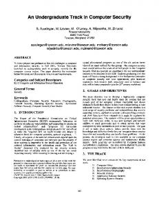
2.5 Containment Most computer viruses including network worms initially spread slowly, achieve a critical mass, and then spread rapidly across the Internet. The number of new infections eventually levels for one of two primary causes: the worm achieves its critical mass or the preventive measures become effective. A worm reaches its critical mass when it has infected as many computers as it can by using a random scanning algorithm. Network administrators generally initiate preventive measures when they are informed of a worm. Figure 2 illustrates the number of infected hosts in a subnet of the Internet during the Code Red v2 epidemic of July 2001 [Moore and Shannon, 2001].
Figure 2. Code Red v2 time-series spread 19
Korzyk [1988] developed a time-series forecasting model for predicting Internet security threats. This model is based on the assumption that after a certain time interval, the Internet weathers the effects of a network worm. Further work in this area has led to an effective measurement methodology for a time-series model of a network worm [Yurcik, Korzyk, and Loomis, 2000]. The goal of worm containment, in a broad sense, is to recognize (either on end systems or in the network traffic) that a worm is spreading and to disrupt its spread before it can cause widespread harm [Staniford, 2003]. However, this goal cannot always be achieved, and counter measures, including patching, upgrading, firewalling and disconnection after a worm incident, are still widely used. In principal, counter measures can quickly reduce, or even stop the spread of infection, thereby mitigating the overall threat and providing additional time for more heavyweight treatment measures to be developed and deployed. Cleaning up after a worm incident is an example of reactive security in an organization. However, proactive security, including immediate upgrading and patching of systems has proven costly in some enterprises because it may break some critical running applications. A mix of proactive and reactive security is considered a good approach where new patches and upgrades are verified on test systems before being applied to the critical system [Cheswick et al., 2003]. Based on the classical Kermack-McKendrick epidemic model [Freunthal, 1980], researchers have formulated a two-factor model [Zou et al., 2002] for the spread of a network worm. This model leads to a better understanding and prediction of the scale and speed of the 20
spread of network worms. This model takes into account the human countermeasures including removing both susceptible and infectious computers from the Internet after systems and network administrators learned of the spread of the Code Red v2 worm. As more people learn of a worm, an increasing number implement some form of counter measure–patching or upgrading susceptible computers, setting up firewalls on edge routers, or simply disconnecting their systems from the Internet. Two primary containment strategies have proved effective [Moore et al., 2003]: content filtering and address blacklisting. Address blacklisting is an extension of spam lists where specific IP addresses are blacklisted and all transactions from that specific IP are dropped. Content filtering is an advanced technique where the network packets, which contain malicious code, are identified and dropped. Intrusion Detection Systems generally use some form of a content filtering mechanism. Bayesian filtering algorithms have been used for content filtering and generally yield a better output than address blacklisting methods by an order of magnitude. However, they are also computationally intensive. Nojiri et al. [2003] propose a friend system for co-operatively mitigating huge intrusion incidents such as a worm epidemic. Cooperating members communicate with others by a "friend protocol" that spreads attack reports to potentially vulnerable uninfected sites. However, during worm epidemic conditions, the network itself is under duress. Adding more traffic to the networks creates a race condition where protocol traffic and worm traffic compete for the same resources. Williamson [2002] suggests using virus throttling for worm containment. Virus throttling involves observing the type pf connections 21
that a machine makes with a new machine under normal conditions (generally low level below 0.5 – 1Hz). In the same manner, a worm makes high-level connections to new machines (for example, the Code Red virus made connections at the rate of approximately 200Hz [Williamson, 2002]) Once these facts are gathered, additional software can be implemented in the network stack of an operating system that limits the rate that a host can make outbound connections to new hosts (new in the sense of not being in a cache of recently visited hosts). An obvious limitation of this technique is that, if the worm is able to get system access on the host, it can disable the filtering mechanism and, thus, spread unchecked. The Counter Malice product [Silicon Defense Inc., 2002] operates by extending the research of Williamson [2002] to a network device. The device makes the network more resilient to the worm; however, the worm must first infect the network that has the device before the device can impede the flow of the virus.
22
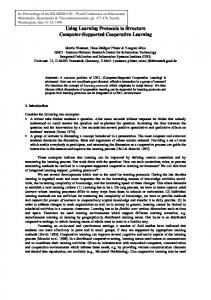
2.6 Intrusion Detection Systems Several methods to counter the emergence of worms have been investigated. Prominent among these are the network-based IDS, which monitor the network for any suspicious activity. When such an activity is discovered, it is immediately reported via a pre-determined notification method. The idea of a DIDS has been considered since the late 1980s. However, not until the Internet connected computers across the globe was the importance of correlated data from various agents understood. Correlated data helps in understanding major occurrences of intrusions. For this reason, large-scale DIDS were developed in the late 1990s [Inella, 2001]. Robbins [2002] outlines the primary reasons for moving from individual IDS to a DIDS. Distributed Intrusion Detection Systems proved effective in the rapid assessment of virus activity across the Internet. A good example is the detection of the 2001 Lion worm at the Internet Storm Center at the SANS (SysAdmin, Audit, Network Security) Institute [SANS, 2001a]. Distributed Intrusion Detection Systems are now widely accepted as standards for detecting intrusions on a worldwide scale. They receive data from various sources, such as personal firewall logs, enterprise IDS logs and educational institutions. The data are analyzed and the required authorities are contacted via e-mail. This strategy helps many ISP and domain owners to identify computers on their networks with malicious software. An example of such a system is shown in Figure 3.
23
Figure 3. Dshield Distributed Intrusion Detection System Unfortunately, DIDS still cannot predict the spread of viruses across the Internet. However, the detection and prediction of the movements of these viruses within a LAN the data management systems need in deciding their next course of action. For example, if subnets P and Q have been attacked and a prediction mechanism indicates the possibility of subnets A and B being under immediate threat, the management system can choose to alert the network administrators of those subnets with an emergency message. At the same time, the network administrators of the already infected subnets can be notified to start disaster recovery. The problem facing many LAN is the rapid dissemination and transfer of information concerning attacks. Most DIDS can detect a large-scale attack across the Internet and warn their clients immediately. However, if multiple network administrators each control
24
their individual subnets, the time required to disperse information to the individuals who can make the changes is vital.
25
2.7 Biological Epidemiology The Center for Disease Control (CDC) defines epidemiology as "the study of the distribution and determinants of health-related states in specified populations, and the application of this study to control health problems" [CDC, 2003a]. Depending on the population it affects, epidemiology can span various fields, such as plant epidemiology, human epidemiology, and animal epidemiology. Because the general analytical methods and techniques applied to epidemiology can be the same across different populations, some methods can span all fields. Consequently, intense investigations in the field of epidemiology have attempted to determine the causes of an epidemic and the solution to its problems. However, since epidemics affecting each species (e.g. plants, animals, and humans) have different characteristics, different analytical methods are preferred for each. This present research has led to a significant understanding of epidemiological models. Epidemiological models are primarily classified into three categories: box or compartmental models, continuous space models, and network models. Box models divide populations into compartments, and the spread of disease across the compartments is determined if possible. These models assume that contacts within a compartment are homogeneously distributed. Box models have been the standard for dealing with spatial heterogeneity in human populations [Anderson and May, 1984]. Many of the results from box models are applicable to human and animal populations. Continuous space models represent the surface of Earth as a plane and therefore simplify the mathematical description of space [Bolker, 1997]. They assist in qualitatively understanding the processes governing spatial spread. Lattice models have been used with powerful
26
analytical tools to approximate the dynamics of the epidemic in a more realistic spatial setting. The grid cell structure of lattice nodes has been successful in using fixed dispersion methods for predicting the spatial movements of plant epidemics. These dispersion methods depend on infection vectors such as wind, animals, and spores. Network models combine the most realistic components of the continuous-space and the box models. These models have helped construct approximations of the true contact structure of humans [Bolker, 1997]. Network models have been very useful in determining the spatial spread of human epidemics. However, they are also the most computationally and analytically difficult models to construct.
27
2.8 Computer Epidemic Models Kephart et al. [1993] used lattice models with directed graphs to track the spatial spread of early computer viruses. Each computer is considered as a node in the model. The computer where the infection started was considered in the center. All connections to each node were the computers that modeled the human relationship between the owners of he computers. This type of model was applied to a lattice structure with three neighbors. This lattice structure resembled a cube, which formed a grid cell of eight. It is observed that there is clustering in the center. This formation indicated that the spread is limited to a circular region around the first incidence of the virus. However, the viruses under consideration by Kephart et al. [1993] were boot sector viruses, which spread via human contact structure. The above model is no longer valid because current viruses use random scanning of IP addresses to determine the next target. However, the Kephart et al. [1993] research serves as the starting point and the main inspiration for the present research. Related work in the field of computer virus prediction has concentrated on game theory for predicting the actions of attackers on individual computers and for predicting when an attack might occur [Liu and Li, 2001]. Recent research has concentrated on fuzzy logic [Botha and Solms, 2003] and behavioral assessment to predict attacks. However, most of these techniques are only practical for determining attacks on individual computers. Based on the simple epidemic model [Daley and Gani, 1999] and the Kermack-McKendrick threshold model [Kermack and McKendrick, 1932], a two-factor worm model was presented by Zou et al.. [2002]. The model accurately follows the spread of the 2001 Code Red worm. The two-factor model helps predict the temporal 28
characteristics of the worm and shows an exponential rise in the spread of the worm in the early stages when the networks have relatively normal levels of traffic flow. At this stage, most computers are not yet infected with the worm. Zou et al. [2003] suggested using a Kalman filter [Kriedl and Frazier, 2003] on the LAN to detect the propagation of the worm at an early stage. The filter is based on observed illegitimate scan traffic. The Kalman filter is an exponential filter, which increases quarantine strategies as the amount of traffic on the Internet increases. However, this filter requires the transmission of status from agents across the network at a time when the network is heavily loaded with worm packets. If the agents are not able to communicate, the filter fails. This chapter has presented the background necessary for understanding the core concepts discussed later in this thesis. Discussion continues on the similarities and differences between plant and computer epidemiology and the choice of the particular statistical variables and models used in this analysis.
29
3 Computer vs. Biological Epidemics Epidemic models in earlier work on the spread of a computer virus concentrated on human epidemics. However, most network worms do not spread in many ways similar to human epidemic models, primarily due to the static (immovable) nature of computers as opposed to the flexible (movable) nature of humans. Infected humans can spread the virus spatially by their movement to a susceptible population [Anderson and May, 1985; Morris, 1994]. Another major shortcoming of earlier, worm-oriented, epidemic models [Staniford et al., 2002; Zou et al., 2002] is that they were not spatial in nature, i.e., these models did not support the estimation of spatial flow of a computer worm within the computer network. Plant epidemic models, however, are inherently spatial because they are used to develop preventive measures. They have a wide variety of spatial characteristics and models that can be inherently applied to computer networks. This section outlines the primary reasons for using plant epidemiology in this analysis. Parameters for this research are also outlines, along with their importance.
30
3.1 Similarities Staniford et al. [2002] provided a proof of concept for network worms following the Susceptible-Infected (SI) model for the spread of biological epidemics. The number of vulnerable hosts infected at time t follows the equation
α=
e vS(t −T ) 1+ e
vS(t −T )
where α is the number of hosts infected at time t, v is the vulnerability density (number of susceptible computers), S is the scan rate of the virus, and T is the time when all vulnerable computers become infected. Zou et al. [2003] further modified this equation to adjust for the preventive measures taken by administrators after they became aware of the worm. The above equation gives rise to a characteristic S-shaped form of the infection incidence as a function of time. Figure 2 (in Section 2.5) depicts the number of computers affected by the Code Red v2 virus as observed at the Cooperative Association for Internet Data Analysis (CAIDA) center; it is an S-shaped curve. Temporal logistic analysis of plant epidemics also produces a similar equation [Campbell and Madden, 1990].
y=
1 1 + Be − r t L
where y is the disease incidence, t is the time, r L is the apparent infection rate, and B = (1-y0)/y0 where y0 is the number of plants infected at the start when t = 0. This equation produces an S shaped 31
curve similar to that seen in the case of the Code Red worm. The timeseries equations indicate that plant and computer epidemics are similar in their temporal characteristics. The time-series characteristics do not have an effect on the spatial nature of the infection. However, these similar characteristics indicate that similar spatial characteristics exist. Wassenar and Blaser [2002] describe the similarities between plant and computer epidemics and illustrate how the evolution of virus strains in computers follows the well-known development patterns of strains in biological viruses. Their work was inspired by parallels that scientists drew between the proliferation of computer viruses and the spread of agricultural catastrophes such as the Dutch Elm disease [Lemos, 2004]. Virulence genes in plants are constantly “stolen” and reused, similar to the techniques employed by computer worm creators. Plant epidemics reflect the way in which computer virus spread because plant epidemics also depend upon external factors, such as wind, rain, and spore dispersal, to spread the epidemic. These factors have analogous counterparts in computer virus epidemics. Continuous epidemic models are generally used to model the spread of plant epidemics. These are generally lattice models where grid cells and lattice nodes are used for modeling. Due to the basic nature of the computer network architecture, all the computers in a grid cell, the nearest neighbor, and the lattice nodes can be easily identified. Three phases are distinct in plant epidemic spread: liberation, transport, and deposition. All three phases depend on external conditions. Wind and rain change the liberation phase, affect transport through the medium, and randomly distribute the deposition of the infection vector (Figure 4).
32
Figure 4. Virus transport mechanism in plant epidemics Just as air is used as the transport mechanism for most epidemics, so the Internet is used as the transport mechanism for a majority of viruses in the Internet area. Wind and rain affect the transport mechanism in plant epidemics by causing changes in the transport medium, resulting in a random pattern of deposition. Subsequently, nothing ensures that the infection vector will land on a susceptible plant or even on a plant at all (the infection vector may land in a neutral, uninfectable place). In the same manner, the random IP generation mechanism in computer epidemics generates IP addresses without any certainty that the end point exists. The virus transfer mechanism in computer networks is given in Figure 5.
33
Figure 5. Worm transport in computer networks Another point worth noting here is that both plants and computers are immobile by their very nature. Therefore, they require other mechanisms to spread their infection. The infection vector does not infect plants that are protected against the disease. Similarly, a virus cannot infect computers that have been patched against vulnerability in the software. The stationary nature of computers also allows for easy characterization of computers into subnets similar to quadrant structures used in agricultural fields. Table 1 gives similarities between plant and computer epidemics.
34
Plant Epidemics
Computer Epidemics
Virulence genes “stolen” and reused
New
worms
reuse
old
software code
External environmental factors influence spread of disease
External computer network factors influence spread of network worms
Temporal characteristics of plant epidemics
Temporal characteristic of computer epidemics
1 y= 1 + Be − r t
υ S ( t −T )
α=
L
y = disease incidence,
e 1+ e
υ S ( t −T )
α = fraction of hosts infected at time t,
t = time, rL = the apparent infection rate, B = (1-y0)/y0, and
v = vulnerability density, S = scan rate of the virus,
y0 = number of infecteds at t=0.
and T = time when all vulnerable computers get infected
Table 1. Similarities between plant and computer epidemics
3.2 Differences Although similarities can be noted between computer and biological epidemics, some fundamental differences also exist. These differences can be identified in the transmission medium and in the availability of a recipient. The transmission medium used by the infection vector to move from one host to another in computer networks has physical limitations, which have often been reached. For example, most computer networks reached their maximum capacity during the January 2003 Slammer epidemic. On the other hand, the transmission medium for some
35
biological epidemics, such as air, can only become theoretically saturated. Thus, insights into how saturation of the transmission medium affects the spread of the infection vector cannot be ascertained from biological epidemiology. In addition, the most important condition for infection in biological epidemics is that the infection vector reaches a susceptible plant. For computer epidemics, two extremely important conditions must be met: the infection vector has to reach the intended recipient and the susceptible parameter must be present on the host. Although these differences can change the values of the parameters in epidemic models, the concept of the two models still overlap. As noted, this research only analyzed one particular class of computer viruses, network worms.
36
3.3 Extending Biological Parameters The next step in this research was to choose which parameters from plant epidemics would be most helpful in determining the spatial relation between virus incidences. Since the spatial spread of the disease is the focus of this research, characteristics are modeled that help determine a spatial dependence (e.g. spatial autocorrelation and spatial clustering index). Spatial methods often included in the analysis of plant epidemics are spatial autocorrelation and the Spatial Analysis by Distance IndicEs (SADIE) clustering index. The SADIE clustering index [Perry, 2001] determines the spatial relation among entities in point-referenced data. Aggregated, patchy, contagious, clustered, and clumped are descriptors that all refer to patterns arising from positive or attractive interactions among such individuals in point-referenced data. Thus, the index determines the presence of clusters in a field. Spatial autocorrelation [Cliff and Ord, 1981] measures the extent to which the occurrence of an event in an areal unit constrains, or makes more probable, the occurrence of an event in a neighboring areal unit. In simple terms, spatial autocorrelation is based on the first law of geography [Tobler, 1970]: near objects are more similar than objects that are more distant. Application of spatial autocorrelation to local area networks identifies the relation between two class C networks (a class C network is one in which the first 16 bits of the 32 bit IP address is fixed [for example, 128.173.xxx.xxx]) that receive the same intrusion or receive the same virus. Spatial autocorrelation can be quantified by various methods. This research computes spatial autocorrelation by plotting
37
the worldwide metrics, Moran’s I values, for spatial autocorrelation [Moran, 1948]. An important consideration in spatial autocorrelation is its high dependence on the size of the area designated as a group. Unless the correct group size is chosen, spatial autocorrelation may not be evident. Since a natural topological divide exists in computer networks, each class C network can be designated as a quadrant. Thus, two different aspects of the network, topology and geography, are used as the main underlying principles for observing autocorrelation in the incidences of network worms in a subnet. The entire class B (class B network is one in which the first 8 bits of the 32 bit IP address is fixed, for example, 128.xxx.xxx.xxx) network (analogous to a field in plant epidemiology) can be construed as a 16 x 16 grid structure with serial ordering of the class C networks. Instead of the serial ordering, neighbors are identified by their geographical proximities in the geography-based analysis. Similarly, neighbors are identified by distance with respect to network distances (hop counts) in the topology-based analysis. Each subnet within the LAN can be denoted as one lattice node that is arranged on a lattice model with 254 possible neighbors (since a class B network can contain a maximum of 255). However, the meaning of the word "neighbor" can be further expanded to include and indicate exactly which lattice nodes are close to each other. Two re-definitions are currently under consideration: neighbors can be determined by a geographical measure or by a measure based on topological structure. Since neighbors are close to each other, the distance between topological neighbors can be determined from the network hop count 38
and the geographical distance based on the physical distances between the buildings in which the subnets are located. The next subnet need not be the neighbor of a lattice node; in fact, the neighboring node may be geographically and topologically distant.
39
4 Evaluation Parameter Spatial autocorrelation is the evaluation parameter used in this research. Different methods are available for calculating spatial autocorrelation. Certain factors must be considered, and some extensions must be made. Neighborhood relations are defined next and how the definitions of neighborhood are extended to fit computer networks.
40
4.1 Spatial Autocorrelation Spatial autocorrelation is defined here as the relationship among values of a single incidence (in this research, the number of infections) that comes from the arrangement of the areas in which these values occur. It measures the similarity of objects within an area, i.e., the degree to which a spatial phenomenon is correlated to itself in space [Cliff and Ord, 1981]. In addition, spatial autocorrelation determines the level of interdependence between the values of the variables, and the nature and strength of the interdependence. In the context of plant epidemiology, spatial autocorrelation tests whether the extent of infection in a particular location depends on the existence of the infection in its neighbors. In plant epidemiology, spatial autocorrelation answers one simple question: is a particular location developing a plant epidemic because its neighbors have the same infection? Extending the same logic to computer epidemiology, the question becomes: is the incidence of a network worm in a particular location dependent on its neighbors being infected with the same worm? Spatial autocorrelation is an assessment of the correlation of a variable (in this research, extent of infection) with reference to its location, i.e., where it occurs in the space of the current consideration. Spatial autocorrelation assesses whether the values in a given space are interrelated and, if so, determines if there is a spatial pattern to the correlation, i.e. does spatial autocorrelation exist. Spatial autocorrelation can be positive or negative. No spatial autocorrelation is exhibited when the neighbors of a grid square under consideration have different properties from those of the grid square
41
itself. A checker board (such as one shown in Figure 6) is a good example of the absence of spatial autocorrelation. Black squares indicate the presence of an infection while the white squares indicate the absence of infection. The squares adjacent to each white square are black, indicating that the nearest neighbors are not similar. Under these conditions, only the adjacent cells that have a common side as neighbors are considered. Such a neighborhood definition is called the rook’s spatial contiguity definition.
Figure 6. No spatial autocorrelation The highest spatial autocorrelation exists when all squares have the same property. In Figure 7, the color black represents all grid squares. This example represents the maximum spatial autocorrelation possible.
Figure 7. Highest value of spatial autocorrelation
42
4.2 Measuring Spatial Autocorrelation Spatial autocorrelation can be computed by using some index of covariance for a series of distances (or distance classes) from each point. The resulting correlogram (correlation diagram) illustrates autocorrelation at each lag distance. Membership in a given distance class is defined by assigning a weight to each pair of points in the analysis; typically this weight is a simple indicator function, taking on a value of 1 if within the distance class and all else 0 (weights may also be defined in other ways, in which case they can take on real values). The weighting matrix for the geographical and the topological cases in this research is defined separately, and is dealt with in greater detail in Section 5.4. Spatial autocorrelation exists when a systematic spatial variation occurs in the values of a given variable. This variation can exist in two forms, positive or negative spatial autocorrelation. In the positive case, the value of a variable at a given location tends to be similar to the values of that variable in nearby locations. If the value of some variable is low in a given location, the presence of spatial autocorrelation indicates that nearby values are also low. Conversely, negative spatial autocorrelation is characterized by dissimilar values in nearby locations.
For example, a low incidence value may be
surrounded by high values in nearby locations when negative spatial autocorrelation exists. In this research, a high spatial autocorrelation value indicates that if an individual entity showing the existence of infection will have neighbors with similar values. The implication is that if the neighbors are not currently infected have a high likelihood of showing infection in the future. The value of spatial autocorrelation can be used to predict the likelihood of the infection spreading to neighbors of the entity itself.
43
The spatial pattern of a distribution is defined by the arrangement of individual entities in space and the relationships among them. The capability of evaluating spatial patterns is also a prerequisite to understanding the complicated processes underlying the distribution of a phenomenon. As such, statistics of spatial autocorrelation provide a useful indicator of these spatial patterns. There are many indicators of spatial autocorrelation [Cliff and Ord, 1981;Chou, 1997;Goodchild, 1987;Haining 1990]: 1. Global indicators of spatial association, join count statistics; Moran's I [Moran, 1948] and Geary's c [Geary, 1954] 2. Local indicators of spatial association—LISA Gi [Anselin, 1995] and Gi* statistics [Ord and Getis, 1995] 3. The variogram approach to spatial association [Matheron, 1963] for geostatistical perspective In this study, spatial autocorrelation calculations used the global Moran's I [Moran, 1948] methods. These statistics indicate the degree of spatial association as reflected in the data set as a whole. This research was primarily interested in an estimate of the autocorrelation over the entire space under consideration. Moran’s I computations gave values between -1 and +1; -1 is the maximum negative spatial autocorrelation detected and +1 the maximum positive spatial autocorrelation. In plant epidemiology, Moran's I is the most commonly used coefficient in univariate autocorrelation analyses [Diniz-Filio and Telles, 2002]. Also, Moran’s I allows geographic distances to be partitioned into discrete classes. In computer networks, most computers and subnets lie in discrete subnetworks. This method better supports
44
analysis of spatial autocorrelation. The common use of Moran's I in plant epidemiology also influenced its choice in this research.
45
4.3 Calculating Spatial Autocorrelation To obtain the spatial autocorrelation coefficient of a variable, the values of that variable must be correlated for pairs of localities. However, only those pairs of localities that are considered neighbors were correlated. These neighbors are designated as the weighting matrix. Each row of the matrix represents the neighborhood relation of the spatial place under consideration to the other grid spaces. For example, in the sample grid in Figure 8a, the corresponding row in the neighborhood matrix for grid-square 5 (considering queen’s neighborhood definition) is shown in Figure 8b. Queen’s neighborhood definition includes grid spaces that share a vertex or a side with the grid under consideration. 0
1
2
3
4
5
6
7
8
Figure 8a. Grid space layout
5
0
1
2
3
4
5
6
7
8
0
1
1
0
1
0
0
1
1
Figure 8b. Weight matrix for grid-square 5 considering grid space in 8a A very simple weighting scheme is used in the above example. Every neighbor who has either a side or a vertex in common with the grid square under consideration (5) is assigned a weight of 1; all others are assigned a weight of 0.
46
The weighting matrix is adaptable so that it reflects the situation under consideration. The weighting scheme used in the research for the two evaluation cases, geographical and topological, are explained in Section 5.4. Moran’s I is the weighted product correlation coefficient dependent upon the weights assigned which depict proximity. Moran’s I coefficient is calculated as N
I=
N∑ i =1
N , j ≠i
∑W Z Z ij
i
j
j =1 N
So ∑ Zi 2 i =1
where N equals the number of regions, wij is a weight denoting the strength of the connection between areas i and j, zi is the rate in region i centered about the mean rate (using zi = x i – ave (x); xi is the rate in region i); and S0 is the sum of the weights. S0 is represented as N
N
S 0 = ∑∑ Wij, i ≠ j i =1 j =1
where Wij is a weight denoting the strength of the connection between areas i and j. The null hypothesis for the Moran’s I calculation assumes that the area under consideration is not correlated. The expected value of I under the null hypothesis is
47
E (I ) =
−1 (N − 1)
where N is the number of sample values being considered. The significance (p) of the I value calculated is determined by an asymptotic, normal bell shaped curve. The shape of the curve is determined by the value of variance. Variance is calculated as
where
48
4.4 Neighborhood The concept of neighborhood is crucial to the determination of spatial autocorrelation. The choice of the type of neighborhood depends on the relationship under examination. In this research, the focus is on the spatial relation between network worm incidents in a geographically close LAN. Neighborhood relations are determined for the geographical and topological cases.
49
4.4.1 Geographical In traditional plant epidemiology, when grid spaces are under consideration, movements of different pieces of the game of chess are used to define neighborhood characteristics. Figure 9 shows the different kinds of neighborhoods that exist at the first spatial lag for the center square. The black squares indicate neighbors. Therefore, Figure 10a displays the rooks neighborhood; Figure 10b shows the bishop neighborhood; Figure 10c shows the queens neighborhood.
a
b
c
Figure 9. Neighborhood definitions a) rook neighborhood, b) bishop neighborhood, and c) queens neighborhood The same movements can be used to explain the neighborhoods at several distances. Figure 10 shows the rooks neighborhood at spatial lag 2 for the center square.
Figure 10. Rooks neighborhood with spatial lag 2
50
A 1:50 scale map of Virginia Tech was divided into an 18 x 18 grid structure. A 1:100 scaled map of Virginia Tech without the grid partitions is shown in Figure 11. A fragmented 1:50 scaled map of Virginia Tech can be obtained from the Virginia Tech Architects website at (http://www.unirel.vt.edu). The grid spaces were approximated via an overlaid standard 8 x 8 graphing sheet. Two squares on the sheet were joined such that each grid square eventually was a 16cm x 16cm square on the sheet. Each grid square contained
approximately
one
building
on
campus.
Figure 11. 1:100 scaled map of Virginia Tech To maximize the analysis of influence but still maintain a statistically computable number of combinations, the queens neighborhood structure with only a first order spatial lag only was considered for our analysis.
51
In addition, certain neighbors might not exist at all spatially within this neighborhood structure. Absence of computers in a certain portion of the grid, such as a lake or building with no computers (greenhouses) resulted in the reduction of the weight of the nonexistent neighbor to 0. Non-existent neighbors would not have any effect on the number of infections within another grid square. In addition, the effect one neighbor can have on another neighbor does not increase when a neighbor is unable to affect the infections. Therefore, their weight was maintained at a constant 1 value. Consequently, a first order neighbor if it had computers was assigned a weight of 1, otherwise it was assigned a weight of 0. This process was repeated for each grid square, thus producing the weight matrix for the geographical case.
52
4.4.2 Topological The topological case is quite different and more complicated than the geographical case. No natural divide is evident for recognizing if a computer is a neighbor of another computer and for assessing how much consideration should be given to this problem. At the highest level, a computer topological network has the structure of a tree (Figure 12).
Core router
Subnet router
Computer A
Computer B
Subnet router
Subnet router
Computer C
Computer D
Figure 12. Tree hierarchies of computer networks Figure 12 indicates that not every computer has neighbors at its level. This research only considered the class C level domain, so the task is somewhat simpler. However, the issue of levels and neighborhoods remains an equally complex problem as the subnet structure in Figure 13 shows.
53
Core router
Subnet Router
Primary subnet router
Secondary subnet router Primary subnet router
Subnet router
Primary subnet router
Figure 13. Subnet structure under a core router Once the number of subnets begins increasing dramatically, redundancy is introduced into network paths. This redundancy helps networks stay active, even if one particular route is full or one section of the network is down. Redundancy in network topological structures can be modified by various means. An example of a redundant structure is the star network topology shown in Figure 14. This structure produces multiple ways to communicate from one subnet to another. However, in practice, computer network architects use a combination of different topologies that they have developed from their intimate knowledge of the network.
54
B
A C
D
Figure 14. Star network topology for subnets A, B, C, and D The weight of the edge between two subnets is determined by the probability of an infection from a computer in one of the subnets under consideration following a network topological route to a computer in the other subnet under consideration. The neighborhood weight, therefore, primarily depends on the subnet connections of the network topology. Figure 15 demonstrates the calculations of neighborhood weight.
Core Router
Subnet 1
Subnet 2
Subnet 3
Subnet 4
Subnet 5
Subnet 6
Router
Subnet 7
Subnet 10
Subnet 8
Subnet 9
Figure 15. Example subnet structure The probability that subnet 4 will choose subnet 5 over all its neighbors is 1/7. This calculation comes from the seven different paths
55
that the infection can take on an outward bound path from subnet 4. Therefore in the weight matrix row for subnet 4, the weight for subnet 5 is set as 1/7. However, if a subnet is not in the same child of the same parent, then end-to-end probabilities are used. To determine the weight of the neighborhood between subnet 4 and subnet 9 (Figure 16), the probabilities of direct neighbors from 4 to the parent of 9 is 1/7. The probability that the choice at this point will be subnet 9 is 1/4. Therefore, the total probability is 1/7 x 1/4 = 1/28. Finally, all the weights for the subnet are normalized so that the weight of each individual subnet is normalized to 1. In effect, all the probabilities are summed up and then each probability is divided by the sum of all probabilities to produce the weight. Such a strategy leads to an exponential weighting scheme as the distance changes. To simplify the weighting scheme, only subnets under one core router are considered to be neighbors. The actual topological structure beyond the core routers is abundant with redundancies. Also, the probability values become extremely small ( Select source, sourceport, target, targetport, date, time from reports_731805 where (source like ‘128.173.%’ and targetport = ‘1434’); Figure 16. Sample SQL Query Information collected in the above manner is stored in another table in the MySQL database. Other analytic tools use the data stored by the above methods for calculations of spatial autocorrelation.
59
5.1.2 Analysis Tools Calculation of spatial autocorrelation requires two primary sets of values: the actual number of incidences in each grid or subnet and the neighborhood relationship between the individual grids or subnets. The analytic tools are used in calculations of these sets of values. The neighborhood relationship between the entity spaces is stored in a 2-dimensional matrix. However, the number of incidences in each entity space is stored as a list in a file.
5.1.2.1 Neighbor Matrix Development Tool In order to obtain statistical values for spatial autocorrelation, a matrix that details the relationship of the neighborhood is required. A tool was developed using gcc 3.1 and tested on Open BSD using Darwin. This tool interacts with a MySQL database using MySQL’s C Application Protocol Interface (API). The database stores information on the location of an entity space with regards to the entire space. The basic output of this part of the program is a text file containing the relationships in matrix form. The program must first be compiled to form an executable. The tool can be executed from the Unix command line by supplying two arguments after the executable name. The first argument indicates the kind of analysis to be performed, geographical (geo) or topological (topo). The second argument is the name of a file containing the grid spaces without a computer in them. An example of a grid space with no computers is a pond or simply a building like a greenhouse. The file supplied in the second argument speeds up the process by skipping computations for the grid spaces in the file. This file is especially helpful if there is large grid space or a large topological network.
60
Output can be redirected to a file from the command line. The source code for the tool is presented in Appendix A. The algorithm for calculating the neighborhood matrix differs for the geographical and topological cases. Calculations for each of these cases are detailed below.
5.1.2.1.1 Geographical Case The neighborhood structure assumes all neighbors of the grid square (considering queens neighborhood) to have a value of 1, except if the grid square is one of the exceptions noted above. Grid squares without a 1 have no influence on the possibility of contracting a virus. The names of those grid squares are stored in the file that is supplied as the second argument during the execution of the tool. If an empty file were provided as the second argument during the execution of the tool, the conclusion is that no grid space is empty. An example of running this case from the command line is shown below. Shell>./executable_name geo file_with_nonexistent_grids.txt
5.1.2.1.2 Topological Case The program internally constructs a tree structure of the neighborhood based upon the location information provided in the MySQL database. After forming the tree structure, the neighborhood weight matrix is calculated using the principles outlined in Section 4.4.2. The weight calculations are based on a probabilistic measure of the topographical path followed by an infection from one subnet under consideration to another. These calculations are only performed if both the subnets under consideration exist below the same core router. 61
In the topological case, the command line execution is similar to the one in the geographical case. An example of running the executable from the command line is shown below. Shell>./executable_name topo file_with_nonexistent_subnets.txt The second argument provided while executing the program code is a file containing all non-existent subnets. This file can be an empty file. However, a file containing the unavailable subnets can help reduce the run-time of the program. Typically, run-time for the topological case is longer than that for the geographical case. Runtimes were consistently recorded around the 20-second time range on a Power PC 800 system with 256 MB of RAM.
5.1.2.2 Incident Aggregation Tool The incident aggregation tool determines the number of infections in each geographical grid space or topological subnet. The infection values are necessary for determining spatial autocorrelation. This tool aggregates log records of incidents that are stored in the MySQL database tables by the SQL queries of the data storage tools. If a geographical analysis of the number of incidents is to be performed, the ip2vtgrid.php script is used. On the other hand, the ip2vttopo.php script is used for a topological analysis. The output of the tool is a list containing an entity space with the corresponding number of incidents on each separate line. In this analysis, the entity space was a grid square for the geographical space and a subnet for the topological case.
62
The incident aggregation tool was developed in PHP (see Appendix B). This tool has been tested on a X86 machine running Linux with 2.4 kernel and PHP 4.2. The tool for the geographical case can be run from the command line as Shell> php ip2vtgrid.php For the topological case, the tool can be run from the command line as Shell> php ip2vttopo.php The output can also be redirected to a file from the command line.
5.1.3 Statistical tools The final group of tools uses a statistical program SAS for the actual calculation of spatial autocorrelation. This research used SAS 8.02 running on a Windows XP platform. Any statistical package that has the capability of calculating spatial autocorrelation could be used for this purpose. The choice of SAS was simply based on resources available as part of the Virginia Tech community. Spatial autocorrelation is calculated using SAS macros that are programmed to use the neighborhood weight matrix and the incident list as input. The output of the SAS macro is the value of Moran’s I spatial autocorrelation with its associated p-values. The p-values indicate the level of confidence in the Moran’s I value obtained.
63
The SAS macros for the geographical and topological calculations of Moran’s I are provided in Appendices C.1 and C.2, respectively.
64
5.2 Data Collection Data was collected at the SANS Internet Storm Center. Data collection was facilitated by Johannes Ullrich at the SANS Internet Storm Center. The Internet Storm Center backs up data occasionally and stores information for interesting periods of worm activity. For this research, data was extracted for the Linux Slapper, SQL Slammer, and MS Blaster network worms (Table 2). Start Date
End Date
Linux Slapper
09/15/2002
09/30/2002
SQL Slammer
01/22/2003
02/10/2003
MS Blaster
08/15/2003
08/31/2003
Table 2. Time periods for data collection Traffic patterns that match these worms can still be found occasionally on the Internet. However, the main phase of any infection is during the early hours of the worm spread. This main phase is illustrated by the exponential rise of the total number of computers infected by the worms (Figure 2 [on page 20]). The Dshield database collects logs and processes them on an hourly basis. Participants may choose to submit logs, at weekly, daily, or even hourly intervals. To collect as many logs as possible for the relevant periods, log data must be collected for at least 15 days after a worm starts spreading. Since people from all over the world submit these logs, the existence of an infected computer on Virginia Tech’s network can be
65
determined by two conditions. The first condition is that an infected computer from the Virginia Tech network has to attempt an infection to a computer having a firewall with logging capabilities. The second condition is that the person owning the machine has to submit the firewall logs to Dshield. Network worms tend to infect computers by selecting random IP addresses and attempting to infect them across the Internet. The spread of a successful worm has to be rapid or network administrators will set up blocks at the perimeter. The rapid spread attempt also ensures that as many computers as possible will be infected in the shortest time possible. For example, the SQL Slammer worm of January 2003 spread across the Internet in approximately 30 minutes. This rapidity results in the worm scanning several IP addresses in a short time. Since these IP addresses are randomly generated, the worm has equal probability of infecting a computer next to it and one across the world. An infected computer will, thus, have attempted to infect computers all over the world with equal probability. Approximately 200 million records are added to the Dshield database each week. The possibility is high that an individual who sends a log will have recorded an intrusion attempt. Although this procedure is not the most foolproof method of detecting all infected computers, most of them can be detected in this way. This research is centered on three major network worms that used a random IP generator to spread from one computer to the next. The time periods for the spread of the worms are detailed in Table 2. Moore and Shannon [2001] and Zou et al. [2003] have shown that the time series spread of a worm follows an exponentially increasing curve. The network worm spreads to almost all susceptible computers in the first 2 days after the worm is released. Consequently, analyzing 66
the data from 15 days will provide all the computers affected by the virus. This section has outlined data collection methods. However, the best method for collecting data for a LAN is by deploying an IP packetsniffing engine on the core router that links the LAN to the Internet. Unfortunately, such data are often not stored and, hence, are unavailable. Dshield or a similar log collection source can be an important resource in this respect.
67
5.3 Data Analysis The sample data collected from the sources mentioned above were analyzed to form a simple list of values using the analytic tools described in Section 5.1. This list contained the number of incidences of the virus in each area under consideration. Only the grid areas in which an infection was possible (i.e. computers were available) were considered. This eliminated all areas such as parking lots and lakes from the data in the geographical case. In the topological case, subnets that did not exist on the network were eliminated from the list. The incidents in an area were standardized to ensure the principle of statistical stationarity. In simple terms, we were simply ensuring that an entity space did not have a higher number of occurrences simply because it had a higher number of computers. The incident aggregation analytic tools in Section 5.2.1.2 produced a list that indicated the percentage of computers in a location that were infected by the virus. This crucial step was necessary to fulfill the statistical stationarity principle. The analytic tools also produced the weighting matrices described in Section 4.3. This weighting matrix and the data obtained in the earlier step were used as input to the SAS program. The SAS Moran’s I macro calculated the spatial autocorrelation (I) and significance values (p) for the virus data provided. The Moran’s I value indicated the extent of spatial autocorrelation. The significance of the spatial autocorrelation was indicated by the p-values produced by the macro. A value below 0.05 was considered fairly significant and acceptable in this research.
68
Finally an agreement test was conducted between the three virus incidences to determine if the spread was in agreement. This agreement test verified that the spatial autocorrelation (I) values were not occurring by chance. Since the starting points of all three epidemics within the Virginia Tech network were different, the agreement test verified that the spatial autocorrelation value remained the same regardless of where the epidemic started within a LAN. In real-world examples, these values may not be exactly the same. However, the agreement test verifies if the values are similar. The expected value of I [Cliff and Ord, 1981] is given as
E (I ) =
−1 (N − 1)
where N is the number of locations under consideration. In the geographic case, the worm could possibly have infected 108 grid squares. Therefore, E(I) = - 0.0094. Similarly, in the topological case, the worm could have infected 146 subnets. Therefore, E(I) = -0.0069.
69
5.4 Results The results are given here in tabular format for easier interpretation. Topological case Number of subnets = 146 E(I) = -0.0069 Worm under Moran’s analysis value MS Blaster SQL Slammer Linux Slapper
-0.0194 0.0093 0.0671
I p-value
0.9530 Cheswick, B., Kocher P., McGraw G.and Rubin A., (2003) "Bacon Ice Cream: The Best Mix of Proactive and Reactive Security", Networld + Interop Conference, April 27 –May 2, 2003 Chou, (1997) "Exploring Spatial Analysis in Geographic Information Systems" Santa Fe, OnWord Press 1997 Cliff, A.D. and Ord, J.K. (1981) "Spatial Processes: Models and Applications" Pion Press Computer Security Institute (2003), 2003 CSI/FBI Computer Crime and Security Survey, , Aug 5, 2003 Daley, D.J. and Gani, J. (1999), "Epidemic Modeling, An Introduction", Cambridge University Press, 1999 Diniz-Filio, J., De Campos Telles, M. (2002), '' Spatial Autocorrelation analysis and the identification of operational units in conservation of continuous population‘’, Conservation biology, August 2002, Volume 16, Issue 4, Page 924 Dshield (2001), "Dshield: About", December 21, 2003, Frauenthal, J. (1980) "Mathematical Modeling in Epidemiology", SpringerVerlag Frederick, K. (2002), "Network Intrusion Detection Signatures- Part 3", January 18, 2004
95
Garfinkel, S., Spafford, G. and Schwartz, A. (2003) "Secure Programming Techniques: Part 4", Practical Unix and Internet Security, 3rd edition, O'Rielly Publication Geary, R. C. (1954). "The contiguity ratio and statistical mapping", Incorporated Statistician 5:115-145 Goodchild M. (1987), "A spatial analytical perspective as geographical information systems", International Journal of Geographical Information Systems1 (4): 327-34 Haining, R. (1990), "Spatial data analysis in the social and environmental sciences", Cambridge: Cambridge University Press Inella, P. (2000), "The evolution of Intrusion Detection Systems", SecurityFocus, November 16, 2001, Kephart, J. O., Chess D. M. and White S. R. (1993), "Computers and Epidemiology", In IEEE Spectrum, 1993 Kermack, W. and McKendrick, A. (1932) "A contribution to the mathematical theory of epidemics. Part II. The problem of endemicity", Proceedings of the Royal Society of London, 138:5583, 1932 Korzyk, A. Sr. (1988) "A Forecasting Model For Internet Security Attacks," National Information System Security Conference, 1998 Kriedl, O. and Frazier, T. (2003) "Feedback control applied to survivability: a host-based autonomic defense system", IEEE transactions on Reliability, Vol 52, No. 3 2003 Lemos, R. (2004) "Seeds of Destruction", Cnet News, January 15, 2004 Liu, P. and Li, L. (2002) "A Game Theoretic Approach to Attack Prediction", Technical Report, PSU-S2-2002-001, Penn State Cyber Security Group, 2002 Marchany, R. (2003) "VT-Dshield site is online- need volunteers", Virginia Tech Techsupport listserv, < http://listserv.vt.edu/cgibin/wa.cgi?A2=ind030>
96
Matheron, G. (1963), "Principles of Geostatistics", Economic Geology, 58, 1246-66 Moore, D. and Shannon, C. (2001), "The spread of the Code-Red worm", CAIDA analysis, Moore, D., Shannon, C., Voelker, G.M. and Savage, S. (2003) "Internet Quarantine: Requirements for Containing Self-Propagating Code", In IEEE INFOCOM, 2003 Moran, P. (1948), "The interpretation of statistical maps. Journal of the Royal Statistical Society", Series B, 10:243-251 Morris, M. (1994) "Epidemiology and Social Networks: modeling structured diffusion", In Wasserman, S. & Galaskiewicz, J., editors "Advances in Social Network Analysis: Research in the social and behavioral sciences”, pg 26-52, Sage, 1994 MySQL (2001) "MySQL Database Server", < http://www.mysql.com/products/mysql/index.html> Nojiri, D., Rowe, J. and Levitt, K. (2003) "Cooperative Response strategies for large-scale attack mitigation", DARPA Information Survivability Conference (2003) Ord, J.K. and Getis, A. "Local Spatial Autocorrelation Statistics: distribution issues and an application", Geographical Analysis, 27:306, 1995 Orman, H. (2003), "The Morris Worm: a fifteen year perspective", IEEE Security and Privacy, Volume 1, Issue 5, Sept - Oct 2003 Paquette, J. (2000) "A history of viruses", SecurityFocus, January 16, 2004 < http://www.securityfocus.com/infocus/1286> Perry, J. (2001) "SADIE", SADIE home pages Reuters (2004), "PC viruses spawn $55 billion loss in 2003", CNET News, January 16, 2004 < http://news.com.com/2100-73495142144.html?tag=cd_top>
97
Robbins, Royce, "Distributed Intrusion Detection Systems: An Introduction and Review", SANS Reading Room, GSEC Practical Assignment, 2002 Salkever, A. (2001), "Patches don't make a security blanket", BusinessWeek Online, January 19, 2004 Silicon Defense, Inc. (2002) "Counter Malice- About", January 19, 2004 < http://www.silicondefense.com/products/countermalice/> Snort Network Intrusion Detection System (2000), "About: Snort", January 12, 2004 Staniford, S. (2003) "Containment of scanning worms in enterprise networks", To appear in Journal of Computer Security Staniford, S., Paxson, V. and Weaver, N. (2002), "How to 0wn the Internet in your spare time", 11th Usenix Security Symposium Symantec corporation (2000a), "Reference: virus", January 11, 2004 < http://securityresponse.symantec.com/avcenter/refa.html - virus> Symantec corporation (2000b), "Reference: worm", January 11, 2004 < http://securityresponse.symantec.com/avcenter/refa.html - worm> Symantec Corporation (2002), "Linux. Slapper. Worm", January 10, 2004 < http://securityresponse.symantec.com/avcenter/venc/data/slapper. worm.html> Symantec Corporation (2003), "W32. Blaster. Worm", January 10, 2004 < http://securityresponse.symantec.com/avcenter/venc/data/w32.blas ter.worm.html>
98
Tobler, W. R. (1970) "A Computer Model Simulating Urban Growth in the Detroit Region" in Economic Geography, 46: 234-240 Travis G., Balas, E., Ripley, D. and Wallace, S. (2003), "Analysis of SQL Slammer worm and it's effects on Indiana University and related institutions", University of Indiana, Technical Report Ullrich, J. (2000), "DSHIELD", January 6, 2004 , Unix Manual Pages, "Rand ()" Wassenar, T. and Blaser, M. (2002) "Contagion on the Internet: Letter to the editor", Emerging Infectious Diseases, Vol 8, March 2002 Williamson, M. (2002) "Throttling Viruses: Restricting Propagation to Defeat Mobile Malicious Code" In Annual Computer Security Applications Conference, 2002 Yurcik, W., Korzyk, A. and Loomis, D. (2000) "Predicting Internet Attacks: On Developing An Effective Measurement Methodology" 18th Annual International Communications Forecasting Conference (ICFC'02) Zou, C.C., Gong W., and Towsley, D. (2002) "Code Red Worm Propagation Modeling and Analysis". 9th ACM Conference on Computer and Communication Security Zou, C.C., Gong, W., and Towsley, D. (2003) "Worm Propagation Modeling and Analysis under Dynamic Quarantine Defense ". Workshop on Rapid Malcode (WORM'03) 2003
99
Appendix Appendix A Appendix A.1: main.cpp #include #include #include #include "checks.cpp" #include "grid.cpp" #include "db_test.cpp" using namespace std; //function defintions bool printFirstLine(char, char, int, int, int[100][19]); int main(int argc, char* argv[]){ if(argc != 3){ cout