SOFTWARE—PRACTICE AND EXPERIENCE, VOL. 25(9), 1021–1044 (SEPTEMBER 1995)
Using PROTEAN for Verifying a Complex Protocol – A Case Study R. LAI Department of Computer Science, and Computer Engineering, La Trobe University, Victoria, Australia 3083 (email:
[email protected]) SUMMARY Communication protocols used in the field have always suffered from failures. Some of these faults are the result of design errors; others are the result of implementation errors. These errors dramatically increase maintenance cost and decrease software reliability. The best time to maintain software is during its design stage. A formal approach to developing a protocol is deemed necessary to improve the quality of communication software and to reduce maintenance costs. Protocol verification plays a major role in achieving these objectives; a protocol is first specified formally and then this formal specification is analysed using a computer-aided tool. PROTEAN is a software tool that verifies a protocol specified formally in Numerical Petri Nets. This paper describes the experience and practice of using PROTEAN to verify a complex protocol and then presents an evaluation of PROTEAN and its associated techniques in the light of protocol software development. The ISO FTAM protocol is used as a case study. KEY WORDS:
PROTEAN; protocol verification; reachability analysis; FTAM
INTRODUCTION Many protocols have been used successfully in the field, but they have almost all suffered from unexpected failures. When the conditions in which the protocols work correctly have been changed, there has been no general method available for determining how they would work under the new conditions. Some of the common faulty behaviours are deadlock, looping, loss of messages and timeout. The cost of maintenance is then very high. The best way to maintain the software is during its development stages. A formal approach to developing protocol is deemed necessary to improve the quality of communication software and to reduce maintenance costs. The Open Systems Interconnection (OSI) Reference Model1 was adopted by the International Standard Organisation (ISO) in 1984. It is a model with seven layers that defines a structure for communications among heterogeneous computer systems. The nature of open systems makes it easier to introduce new errors as standards can be interpreted differently. In addition, the complexity of the protocols makes them very hard to analyse in an informal way. Thus it is necessary for a specification to be based on a formal mathematical model: Formal Description Technique (FDT). Formal specification of a protocol is its description using an FDT. Protocol verification is the demonstration of the correctness of the protocol design represented by its formal specification; it enables design errors to be detected in early stages. If these errors were not detected, it would be extremely costly to fix them after CCC 0038–0644/95/091021–24 1995 by John Wiley & Sons, Ltd.
Received 3 November 1993 Revised 4 October 1994
1022
R. LAI
the system had been implemented. Techniques for specification and verification of computer network protocols have progressed significantly in the past decade. The progress is largely due to the development of state transition approaches to formal specification and to the greater automation of the verification process. Automated protocol verification involves the use of computer tools to verify a communication protocol based on its formal specification.2,3,4 A number of the OSI protocols have been formally specified and verified using different techniques, for example HDLC,5 X.25,6 transport layer,7 session layer,8 and presentation layer.9 Most of this work was on specification; little attention has been paid to how formal specification and verification contributes towards the development of the protocol as a product. To be able to successfully verify a protocol, the availability of a computer-aided tool is mandatory. PROTEAN (PROTocol Emulation and ANalysis),10 developed by Telecom Australia, is a computer-aided tool for the verification of computer communication protocols. It finds faults such as deadlocks, livelocks and maloperations specific to the protocol under test. It is based on an FDT called Numerical Petri Nets (NPNs).11 An NPN specification is the starting point for verification using PROTEAN. In practice, some faults can be uncovered during the process of creating a precise NPN specification. Despite the recent advances in the development of protocol verification, there have been very few applications of these techniques to real complex protocols. Evaluations of FDTs, verification techniques and automated tools have rarely been reported. However, it has been pointed out that such evaluations are very necessary.12 After outlining a protocol development methodology, this paper describes the experience and practice of using PROTEAN to verify a complex protocol and then presents an evaluation of PROTEAN and its associated techniques in the light of protocol software development. The ISO FTAM protocol is used as a case study. PROTEAN has recently been used to verify other real-life ISO protocols13,14,15 and has been extended.16 PROTOCOL DEVELOPMENT METHODOLOGY A methodology for OSI protocol development is proposed here. It is as follows: 1. Informal specification; the requirements of the users are studied. The desired communication services are then specified in a plain language. Some of the details include protocol model, services provided, reliability and handling of errors. 2. Formal specification; is the specification using a formal language, for example mathematics, and enables the specifications to be analysed. 3. Protocol verification; based on the formal specification, it identifies errors early in the development process. Should error be detected, the specification is iterated. 4. Implementation development; is the development of the communication software according to specifications. The development of software can be either manual or automatic. (a) Manual – the codes are generated by the actual writing of software. (b) Semi-automatic – based on the formal specification, a compiler is used to generate an intermediate code, say ’C’. Then the C compiler will be used to generate the executable code. (c) Automatic – the codes are automatically translated from the formal specifications by a high-level compiler.
USING PROTEAN FOR VERIFYING A COMPLEX PROTOCOL
1023
User Requirements Informal Specification Formal Specification
Errors Detected
Protocol Verification Implementation Development
Errors Detected
Conformance Testing Interoperability Testing
Errors Detected
Maintenance
Figure 1. Protocol development process
5. Conformance testing; is the validation of the protocol implementation by testing. The protocol is fed with a selected set of test input , and the output are observed and checked against specifications. 6. Interoperability testing; is the validation of the protocol implementation using implementations from different manufacturers. This ensures that the protocol achieves the purpose of open communication. After the interoperability testing, the implementation enters the maintenance phase. The development process is summarised in Figure 1. NATURES OF FDTs The objectives of ISO in developing FDTs can be found in Reference 17: 1. to enable unambiguous, clear and precise descriptions of OSI standards to be written; 2. to allow such descriptions to be verified for consistency and correctness; 3. to provide clear guidance to designers and implementors of OSI systems as to what, but not how, they should implement; and 4. to act as a sound basis for conformance testing.
1024
R. LAI
The usefulness of an FDT can be judged using a number of criteria. Some of the more important ones are described in Reference 18. 1. Expressive (or modelling) power. An FDT must be capable of expressing or modelling a wide range of properties that are relevant to the description of OSI entities. 2. Analyzability. An FDT must be based on a formal model that supports verification. 3. Modularity. An FDT must support modular forms of specification. Modularity is the decomposition of structuring information. 4. Appropriate level of abstraction. Different levels of abstraction relate to the hiding of details. The definition of certain details may be deferred at one level to facilitate the comprehension of key features. The details may ultimately be defined at a lower level of abstraction. FILE TRANSFER ACCESS AND MANAGEMENT The ISO DIS 8571 File Transfer, Access and Management (FTAM)19,20 protocol is used as a case study for this verification. It is a complex protocol available within the application layer of the OSI reference model.21 It controls the transfer of whole files or parts of files between end-systems. File manipulation facilities are also included for setting and changing file attributes and for creating and deleting files. FTAM supports two services: the Reliable File Service (RFS) and the User Correctable File Service (UCFS). For the RFS, the user states its quality of service requirements, but has no control over error recovery, delegating such considerations to the service provider. For the UCFS, the user has primitives available for error recovery and transfer management. There are 2 protocols specified for FTAM: the Basic Protocol, supporting the UCFS, and the Error Recovery Protocol, supporting the RFS. The Basic Protocol is subdivided into the Basic File Protocol and Bulk Data Transfer Protocol. The Error Recovery Protocol supports the Basic Protocol. The FTAM model The operation of the protocol is modelled by the interaction of two file protocol machines (FPMs). The two FPMs communicate by means of the services available at their lower boundary, in such a way as to provide the service required at their upper boundary. The file service is defined asymmetrically with the file service user ‘A’ being the initiator and file service user ‘B’ being the responder. File user ‘A’ can request and use the UCFS or it can request the RFS. This concept is illustrated in Figure 2. The file service and its supporting protocol are concerned with creating a series of stages, a working environment in which the initiator’s desired activities can take place. This leads to a set of contexts being established. The period for which some parts of the common state held by the service users is valid is called a ‘regime’. As progressively more shared states are established, a nest of corresponding regimes is built up. However, there will in general be a time lag between the establishment of a regime at the two ends of the association. Four types of file regimes are defined: FTAM establishment, file selection, file open, and data transfer. FTAM establishment regime consists of the F-Initialize, F-Terminate, F-UAbort, and F-P-Abort request services; the file selection regime is composed of the F-Select, F-Create, F-Deselect and F-Delete services; the file open regime comprises the F-Open and F-Close services; and the data transfer regime is made up of the F-Read, F-Write, F-Data,
1025
USING PROTEAN FOR VERIFYING A COMPLEX PROTOCOL
A (Initiator)
Reliable File Service User
Reliable File Service User
User Correctable File Service User
Error Recovery FPM
Error Recovery FPM
B (Responder)
User Correctable File Service User
Basic FPM
Basic FPM
Lower Service Provider
Figure 2. FTAM model
F-Data-End, F-Transfer-End, and F-Cancel services. The nesting of FTAM regimes and the different services are shown in Figure 3. NUMERICAL PETRI NETS PROTEAN requires the protocol to be specified in the FDT called Numerical Petri Nets (NPNs),22 an extension of Petri Nets.23 NPNs retain the same basic principles, symbols and modes of operation of Petri nets, while adding a considerable degree of descriptive power. NPNs provide a versatile and visually appealing general graphical model for concurrent systems. The following extensions have been added to Petri net to make it NPN: 1. tokens can have any finite number of attributes, each of which may be one of several different types; 2. the association of global variables with the net; 3. the transition enabling conditions refer not only to the tokens in the input places but also to the values of the global variables; and 4. the firing of a transition may not only remove tokens from the input places and insert tokens to output places but it may also operate on the global variables. NPNs and other FDTs The CCITT Specification and Description Language (SDL) became a CCITT recommendation in 1976, and refined version were published in 1988 and 1989. SDL24 is mainly a language by which to specify and describe the logic of functional processes in a fashion independent of implementation techniques, and is an extension of the finite-state machine (FSM). A deficiency of SDL is that it does not have a strong mathematical basis. It is therefore not used for rigorous verification. It is mainly used for specification. Estelle25,26 is an FDT developed by ISO in collaboration with CCITT. A specification
1026
R. LAI
FTAM Regime File Selection Regime File Open Regime Data Transfer Regime F-READ F-WRITE F-LOCATE F-ERASE
F-TRANSFEREND F-DATA F-DATA-END F-CLOSE
F-OPEN F-CHANGE-ATTRIB F-READ-ATTRIB
F-DESELECT F-DELETE
F-SELECT F-CREATE Filestore Management
F-TERMINATE F-ABORT
F-INITIALIZE Figure 3. FTAM file regimes and services
in Estelle comprises a set of modules which communicate with each other. Modules are specified as extended finite-state machines using facilities in Estelle which consist of a set of extensions to ISO Pascal. Estelle reflects the collaboration between ISO and CCITT as some of its elements may also be found in CCITT’s SDL. However, Estelle has no graphical equivalent. Channels and modules are declared as special data types. The ISO specification language LOTOS27,28 has been developed to assist in the formal definition of protocols and services for computer networks. LOTOS is a type of process algebra which originates from Calculus of Communicating Systems.29 It has features for the description of data structures. Petri nets are among the oldest formal models of concurrent systems. Because of the relatively long existence of Petri net theory, an impressive number of analytical tools exist for Petri nets. One of the major advantages of Petri nets is that they can be described either formally or graphically, thus providing both visual clarity and mathematical rigor. PROTEAN The automated tool to verify the FTAM protocol was developed by Telecom Australia. It is called the PROTocol Emulation and ANalysis or PROTEAN.10 It takes specification in NPNs as input, and produces a reachability graph (RG) as output for the analysis of the protocol under study.
USING PROTEAN FOR VERIFYING A COMPLEX PROTOCOL
1027
PROTEAN is a user friendly menu-driven system, with on-line help and simple error messages. It has two parts. The first is the NPN Analyzer Program, which handles the NPNs and the generation of the reachability graph. The second is a collection of programs which helps the user detect maloperations and other properties of the protocol using the results obtained from the first stage. The NPN analyser program allows NPN subnets to be entered via a keyboard or a file. The NPNs are checked for correct syntax. The subnet NPNs can be recalled and combined with other subnets to form larger NPNs. The NPNs can also be modified, listed and displayed graphically. The NPN is initialised by placing tokens in the places and assigning values to the data variables. A user can then investigate the operation of the net manually or automatically. Verification technique The verification technique used was Reachability Analysis (RA).30 It has the merits of having good verification power and ease of automation. RA explores all the possible sequences of actions by generating all reachable states from a given initial state. Each new state is then analysed to see if a deadlock occurs; the process is repeated for each of the new states until no more states can be generated. The set of all possible states of the system is known as the Reachability Set, which is unique for a given system with a given initial marking. In Petri Nets, the relationship between states is given by an RG. It may be presented in tabular or graphical form. RA is the study of the RG generated for the system being verified. The RG is used to investigate the properties of the protocol being studied The main problem with the RG is that it gets very big and unmanageable as the complexity of the system modelled increases, and thus analysis becomes very intractable. PROTEAN programs PROTEAN contains several programs to investigate properties of an RG. These programs are listed below: NET is the program that reads in files containing NPNs and then generates the RG for them. GRAPH displays an RG produced by the NET program. LIVENESS operates on an RG and identifies all the Strongly Connected Components (SCCs) of the graph, that is groups of markings which can be reached starting from and ending at any member of the group. LANGUAGE reduces an RG to show only the language of specified transitions. SCENARIO takes as its input a sequence of either transitions or markings and outputs a list of sequence from an RG consistent with the input sequence. CYCLE finds all the loops within a graph and determines which of these is the largest. PATH determines which nodes in a graph cannot reach a specified node.
1028
R. LAI
PROTEAN files All the input and output files used by PROTEAN’s programs are as follows: .NET stores the net in a form that can be easily created or edited. It is created by the NET program and is used as input to the NET program. .CMP stores the components of each node of the language graph. It is generated by the LANGUAGE program if component composition details are requested. .CYC lists all cycles found in a graph. It is created by the CYCLE program and is used as input to the GRAPH program. .LAN stores details of a language graph for PROTEAN to use. It is generated by the LANGUAGE program and is used as input to the GRAPH, LIVENESS, LANGUAGE, SCENARIO, CYCLE and PATH programs. .LIS holds the information on a net in a more readable form than in the ‘.net’ file. It is created by the NET program. .LIV stores the liveness graph for use by PROTEAN. It is generated by the LIVENESS program and is used as input to the GRAPH, PATH and SCENARIO programs. .MAR contains the details of all markings in an RG, or a complete record of a single-step run. It is easily read by users. It is output from the NET program and is used as input to the GRAPH program. .PTH lists all the nodes that do not have a path to the specified node. It is created by the PATH program and is used as input to the GRAPH program. .REG is not used by PROTEAN but is produced so that a user has a readable file which contains RG information, and the values of any variables in the net. It also lists any transitions that are not fired when an RG is performed. .RUN stores RG information for use by PROTEAN. It can also store graphic information. It is generated by the NET program and is used as input to the GRAPH, LIVENESS, LANGUAGE, SCENARIO, CYCLE, and PATH programs. .SCC contains a list of the contents of each SCC. It is output by the LIVENESS program and is used as input to the GRAPH program. .SCN lists scenarios found by the Scenario program. It is created by the SCENARIO program and is used as INPUT to the GRAPH program. The interactions between the programs and files of PROTEAN are shown in Figure 4. Protocol properties verified Five protocol properties of FTAM are verified. The definitions of these protocol properties can be found in Reference 31. This section explains how these properties are verified using the files and facilities of PROTEAN.
1029
USING PROTEAN FOR VERIFYING A COMPLEX PROTOCOL
NET
GRAPH
a
|
b
|
PATH
| |
CYCLE
|
LIVENESS
LANGUAGE
| |
|
SCENARIO
where a = and b =
Figure 4. PROTEAN files
1. Deadlock Freeness – means that a protocol never enters the state in which no further progress is possible. The Net program of PROTEAN generates the RG which is stored in the ‘.reg’ file. It identifies all the deadlocks. The Scenario program is then used to trace the causes of deadlocks. 2. Livelock Freeness – means that the system will never get into a situation where nonproductive cycles are possible and the exchange of the same messages is performed. The Liveness program identifies all livelocks. Every terminal node in the liveness graph is a livelock if the SCC consists of two or more markings. 3. Liveness – means that every state of the system is reachable. The ‘.reg’ file contains a list of transitions not fired for a given initial marking. By assigning different initial values to the predicates defined in the nets under investigation, those unfired transitions can be checked if they are ever fired in subsequent simulations. Hence, the protocol can be checked for Liveness. 4. Boundedness – means that during the operation of a protocol the number of messages in each channel between protocol entities can never exceed the capacity of the channel. In NPN terms, it means the total number of tokens in a place for each marking will
1030
R. LAI
A (Initiator)
B (Responder)
Basic FPM
Basic FPM
CASE Figure 5. Basic protocol model
not exceed the maximum capacity of the place. The ‘.mar’ file generated by the Net program gives the list of tokens in each place of the nets for each marking. By examining this file, the boundedness property can be easily checked. 5. Termination/Progress – represents the completion of required services in the finite time. The termination deals with terminating protocols, and means that the protocol always reaches the desired final state. The progress deals with cyclic protocols, and means that the protocol always reaches its initial state. The Language program is used to show the sequences of transitions that are of interest. Hence, it can check if the protocol reaches a desired final state. The Cycle program lists all the cycles, enabling the cyclic behaviour of the protocol to be analysed. VERIFICATION METHODOLOGY Due to the complexity of FTAM, its verification demands a methodology that makes the task feasible. Description A block diagram of the total system to be analysed is as shown in Figure 2. The operations of the Basic Protocol and the Error Recovery Protocol are independent of each other. Hence, their specifications and verifications are done separately. The operation of the basic protocol can be modelled by the interaction of two FPMs communicating by means of the services available at the CASE protocol machine. The concept is illustrated in Figure 5. Likewise, the operation of the error recovery protocol is modelled by two FPMs communicating by means of the services available at the UCFS protocol machine. This is shown in Figure 6. Formal Specifications The specifications in NPNs for the Basic Protocol and Error Recovery Protocol were done separately. For the Basic protocol, it was partitioned into manageable subsystems for specifications. It was subdivided into Basic File Protocol,
USING PROTEAN FOR VERIFYING A COMPLEX PROTOCOL
A (Initiator)
B (Responder)
Error Recovery FPM
Error Recovery FPM
1031
UCFS Figure 6. Error recovery protocol model
Bulk Data Transfer protocol, and Basic File Protocol under grouping control. Each of these subsystems was further divided into entities. Each entity consisted of a number of services. The Error recovery protocol was not further divided into sub-systems for specifications. The specification of each service was done in the same manner as that of the Basic protocol. However, the names of the places were different. The nets were viewed as modelling the operation of the protocol machines. Each service provided by the machine was specified via a separate net. A place was used to represent an input/output port through which data were sent and received, and global variables to represent states. Predicates were used to govern the conditions of the transition firings. Since the approach to using places as ports was chosen, each NPN joined with other nets via places with the same name. The total behaviour of a sub-protocol, and subsequently the whole system, was described by a three-dimensional set of nets formed by stacking the NPNs over places with the same names. Effectively, there were columns of places with planes of nets representing possible or concurrent activities that could occur whenever the necessary conditions are met. The three-dimensional net was illustrated in Figure 7. The specification of a single service in a single net had logical advantages. This approach represented the flow of communication services closely and made it easier to follow the behaviour of the entities involved. The data parameters passed by the protocol were modelled by the ‘attributes’ of the tokens. The specification was based on the Draft International Standard of ISO 8571. The NPN specifications of the whole FTAM protocols were based on the state tables in the Annex of ISO 8571, since the standard stated that the Annex was to take precedence over the text. The NPN specifications of the services of the FTAM protocols can be found in Reference 32. An example of the specifications is shown in Figure 8.
1032
R. LAI
Figure 7. Three-dimensional NPN nets
Analysis The NPNs must first be correctly entered into PROTEAN. They are entered in a net form, with each net modelling a service or function of the protocol machines. This allows the behaviour of various sub-nets to be analysed. There are two methods available in the PROTEAN system to analyse a protocol: the single step and the automatic generation methods. It is not feasible to use the single step method to analyse FTAM as there are too many enabled transitions as more nets are added. Using the second method, an RG is automatically generated. Based on the formal specifications, the logical operation of the protocol was analysed. Using RA as the verification technique, the possible sequences of events and the possible states of the system are considered. Inspection of the RG reveals maloperations, like deadlock. It can also check if the protocol conforms to the requirements of its service specifications. However, the complexity of FTAM required an orderly approach to its analysis. The verification of the Basic protocol is done in three phases: basic file protocol, Bulk data transfer protocol, and Basic file protocol under grouping control. The analysis of the Error recovery protocol is done in one phase. There are many services and regimes defined in the protocol. To analyse the protocol by combining all the nets will make the task insurmountable because the huge RG thus generated makes the analysis impracticable. The selection of nets follows the nesting of the regimes. The behaviour of the protocol was examined when proper combinations of services, as defined in the FTAM regimes shown in Figure 3, were selected. For instance, the combination – F-initialize, F-create, F-select, F-deselect,
1033
USING PROTEAN FOR VERIFYING A COMPLEX PROTOCOL ucfsinA
Aselrq
Bpsduin
caseA
Apduout
PdatinBsel
PdatrqAsel A := select pd
Bpduin
Bselrq [B=initialized]
Fselrq [A=initialized]
Fselin B := f select pd
ucfsA
ucfsB
Fselcf [P4] A := selected
Apduin
Aselin [A=select pd]
PdatinAsel
Apsduin
np4Fselcf [~P4] A := initialized
Fselrp [B=f select pd]
PdatrqBsel [P4] B := selected
Bpduout
caseB
Bselrp
ucfsinB
np4PdatrqBsel [~P4] B := initialized
Figure 8. NPN for file selection
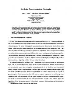
F-delete, and F-terminate – is valid. Unlikely combinations of services have actually been tried out also. But they yielded little information, as such a combination would result in an artificial deadlock produced by PROTEAN. The reason is clear as the regime nesting does not allow such a combination. Situations with error conditions, for example, unsuccessful connection establishment, unsuccessful creation of files, etc, have also been examined. In the NPN model, these are specified by predicates. The nets were simulated under different initial conditions. The properties of the protocol are then investigated using the facilities of PROTEAN. A number of deadlocks have been found. The results of verifying the FTAM protocols can be found in Reference 33 and have been reported to the relevant ISO group; the bugs should not exist in the current FTAM international standard. AN NPN DESCRIPTION To illustrate how a FTAM service is described using NPNs, the File Selection Service of the Basic Protocol is used as an example. Modelling the basic protocol The NPNs are viewed as modelling the operation of the Basic Protocol Machine as shown in Figure 5. The model used 12 places. Their meanings are as follows:
1034
R. LAI
Place
Description
ucfsA ucfsinA Apduout caseA Bpsduin Bpduin ucfsB ucfsinB Bpduout caseB Apsduin Apduin
UCFS user of initiator Input port for UCFS provider of initiator PDU output port for UCFS provider of initiator Input port for CASE provider of initiator PSDU input port for UCFS provider of responder PDU input port for UCFS provider of responder UCFS user of responder Input port for UCFS provider of responder PDU output port for UCFS provider of responder Input port for CASE provider of responder PSDU input port for UCFS provider of initiator PDU input port for UCFS provider of initiator
where PDU means Protocol Data Unit, and PSDU means Presentation Service Data Unit. Informal and specification The NPN diagram for the File Selection primitive is shown in Figure 8. The transitions are described in Table I. 1. Initiator – on receiving an F-SELECT request primitive from the UCFS user while in the state ‘initialized’, the entity adds an F-SELECT request PDU to the current PSDU and terminate the PSDU, and enter the state ‘select pd’. These are modelled by the transitions Fselrq, Aselrq, and PdatrqAsel. 2. Responder – on receiving an F-SELECT request PDU from the UCFS user while in the state ‘initialized’, the entity issues an F-SELECT indication primitive to the UCFS user and enter the state ‘f select pd’. These are modelled by the transitions PdatinBsel, Bselrq, and Fselin. 3. Responder – on receiving an F-SELECT response primitive from the UCFS user while in an ‘f select pd’ state, the entity adds an F-SELECT response PDU to the current PSDU and terminate the PSDU. If the PDU indicates a failure, it enters the state ‘initialized’, otherwise it enters the ‘selected’ state. These are modelled by the transitions Fselrp, Bselrp, PdatrqBsel, and np4PdatrqBsel. 4. Initiator – on receiving an F-SELECT response PDU while in the state ‘select pd’, the entity issues an F-SELECT confirm primitive to the UCFS user. If the primitive carried a result indicating failure, it enters the state ‘initialized’, otherwise it enters the ‘selected’ state. These are modelled by the transitions PdatinAsel, Aselrp, Fselcf, and np4Fselcf. EXAMPLES OF ANALYSIS The analysis was made simpler by the use of PROTEAN facilities and files. Deadlock freeness The Scenario program finds paths in an RG that match a specified transition or marking
1035
USING PROTEAN FOR VERIFYING A COMPLEX PROTOCOL Table I. Description of NPN specification for file selection
Transition
Description of Event
Input/ Output Place
Input/ Output Token
Transition Condition/ Operation
Fselrq
F-select request primitive issued by UCFS user
ucfsA/ ucfsinA
sel rq/ sel rq
A=initialized
Aselrq
Addition of Select request PDU by UCFS provider of initiator
ucfsinA/ Apduout
sel rq/ sel rq Apdu
PdatrqAsel
P-data request primitive issued by UCFS provider of initiator
Apduout/ caseA
sel rq Apdu/ sel rq Apsdu
PdatinBsel
P-data indication primitive issued to UCFS provider of responder
caseA/ Bpsduin
sel rq Apsdu/ sel rq Bpsdu
Bselrq
Receipt of Select request PDU by UCFS provider of responder
Bpsduin/ Bpduin
sel rq Bpsdu/ sel rq Bpdu
B=initialized
Fselin
F-select indication primitive issued to responder
Bpduin/ ucfsB
sel rq Bpdu/ sel in
/ B:=f select pd
Fselrp
F-select response primitive issued by responder
ucfsB/ ucfsinB
sel in/ sel rp
B=f select pd
Bselrp
Addition of Select response PDU by UCFS provider of responder
ucfsinB/ Bpduout
sel rp/ sel rp Bpdu
PdatrqBsel
P-data request primitive issued by UCFS provider of responder on condition P4 is true
Bpduout/ caseB
sel rp Bpdu/ sel rp Bpsdu
P4/ B:=selected
np4PdatrqBsel
P-data request primitive issued by UCFS provider of responder on condition P4 is false
Bpduout/ caseB
sel rp Bpdu/ sel rp Bpsdu
∼P4/ B:=initialized
PdatinAsel
P-data indication primitive issued to UCFS provider of initiator
caseB/ Apsduin
sel rp Bpsdu/ sel rp Apsdu
Aselrp
Receipt of Select response PDU by UCFS provider of initiator
Apsduin/ Apduin
sel rp Apsdu/ sel rp Apdu
A=select pd
Fselcf
F-select confirm primitive issued to UCFS user on condition P4 is true
Apduin/ ucfsA
sel rp Apdu/ sel cf
P4/ A:=selected
np4Fselcf
F-select confirm primitive issued to UCFS user on condition P4 is false
Apduin/ ucfsA
sel rp Apdu/ sel cf
∼P4/ A:=initialized
/ A:=select pd
1036
R. LAI
sequence. The user may exclude particular nodes or transitions from the sequence and may limit the number of paths found. This facility enabled the tracing of specific behaviour in the FTAM protocol and, in particular, was useful for debugging and tracing the cause of deadlocks. For example, the deadlock uncovered for the File Open service has the path listed below. Path 1: 1 -> (Finirq) -> 2 -> (Ainirq) -> 3 -> (Aassrq) -> 4 -> (Aassin) -> 5 -> (Binirq) -> 6 -> (Finiin) -> 7 -> (Finirp) -> 8 -> (Binirp) -> 9 -> (Aassrp) -> 10 -> (Aasscf) -> 11 -> (Ainirp) -> 12 -> (Finicf) -> 13 -> (Fselrq) -> 14 -> (Aselrq) -> 15 -> (PdatrqAsel) -> 16 -> (PdatinBsel) -> 17 -> (Bselrq) -> 18 -> (Fselin) -> 19 -> (Fselrp) -> 20 -> (Bselrp) -> 21 -> (PdatrqBsel) -> 22 -> (PdatinAsel) -> 23 -> (Aselrp) -> 24 -> (Fselcf) -> 25 -> (Fopnrq) -> 26 -> (Aopnrq) -> 27 -> (PdatrqAopn) -> 28 -> (PdatinBopn) -> 29 -> (Bopnrq) -> 30 -> (Fopnin) -> 31 -> (Fopnrp) -> 32 -> (Bopnrp) -> 33 -> (PdatrqBopn) -> 34 -> (PdatinAopn) -> 36 -> (PaltrqBopn) -> 37 -> (Aopnrp) -> 39 -> (p4Fopncf) -> 41 Marking 41, the final marking in that path, is a deadlock. From this sequence generated by Scenario, the reason for the deadlock can be traced. In this instance the deadlock was due to an error in the FTAM state table, where a negation is missing. Livelock freeness The Liveness program determines all of the strongly connected components in an RG. An SCC consists of one or more nodes for each of which a path can be found to every other node in that component. A liveness graph is generated showing how the SCCs of an RG are related. Livelocks occur as leaf nodes of this graph with two or more markings (leaf nodes with one marking are deadlocks). If there is only one strongly connected component, the protocol has no livelocks or deadlocks. Liveness analysis was applied to the RGs generated for the nets created in the specifications of the FTAM protocols. There were no actual livelocks uncovered in the analysis. The deadlock uncovered in the last section can also be analysed using the Liveness program; the liveness graph contained in the ‘.liv’ file had the same path. The corresponding ‘.scc’ file contained a summary of the SCC components; it showed that there was only one component in the leaf node indicated that marking 41 was a deadlock, and that livelock was absent. Liveness The NET program produces an RG in a more readable form stored in the ‘.reg’ file which contains a list of transitions not fired during a particular run. The reason that some of these transitions are not fired is due to the fact that the path leading to these transitions is not executed because the corresponding predicates associated with these paths did not have the right initial values. By changing the initial values of the predicates defined in the nets, those unfired transitions can be checked if they are ever fired in subsequent runs. For example, the F-Select service net discussed above was executed, with the predicate P4 having an initial value of true. The following transitions were listed as unfired in the
USING PROTEAN FOR VERIFYING A COMPLEX PROTOCOL
1037
‘.reg’ file. np4Fselcf np4PdatrqBsel By changing the value of the predicate P4 to false and re-running the net, the previous two unfired transitions, namely np4Fselcf and np4PdatrqBsel, were fired. Thus, every transition defined in the F-Select net was reachable, and the liveness property was verified. Boundedness The Net program generates the ‘.mar’ file containing detailed information about each marking for all markings of an RG. The information includes marking number, the names of places and their contents, namely tokens, and the values of all global variables and predicates of a marking. By examining this file, the number of tokens contained in the places of a net for all markings of an RG can be known. A ‘.mar’ file can possibly hold information for several hundred markings, depending on the size of the RG generated for the previous run. For example, the following lists the contents of marking 1 of an RG: Marking number = 1 Place And Contents ucfsA P-Variables A = ’closed’ P1 = TRUE P3 = TRUE P5 = TRUE P11 = TRUE P21 = TRUE
B = ’closed’ P2 = TRUE P4 = TRUE P10 = TRUE P15 = FALSE P22 = TRUE
In this example, there was only one token residing in the place ‘ucfsA’, the rest of the places of the net did not contain any token. The net was obviously bounded in this case. It was found that during the whole verification exercise the maxmium number of tokens contained in any place of any net was four. The system was therefore k-bounded, where k is four; and the boundedness property was verified. Termination An RG shows all of the possible sequences of all transitions, i.e. the language of all of the transitions. To determine if a protocol meets its service, or to verify other properties, it is useful to determine the language of selected key transitions. The language program reduces the reachability or language graph to show only the sequences of these user-determined key transitions. Language analysis was applied to the transitions representing FTAM services to study the behaviour of the FTAM file regimes. It verifies that the protocol does behave according to the FTAM regimes.
1038
R. LAI 1
2
13
14
15
36
37
38
59
60
Figure 9. Language graph
For example, a language graph for a net that consists of F-initialize, F-select, F-create, F-deselect, F-delete, and F-terminate is shown in Figure 9, where the circles are markings labelled by a number. The transitions which fire to go from numbered one marking to another are as follows: 1 Finirq (F-initialize request) 2 2 Finicf (F-initialize confirm) 13 13 Fselrq (F-select request) 15 13 Fcrerq (F-create request) 14 14 Fcrecf (F-create confirm) 36 15 Fselcf (F-select confirm)
USING PROTEAN FOR VERIFYING A COMPLEX PROTOCOL
1039
36 Fdesrq (F-deselect request) 38 36 Fdelrq (F-delete request) 37 37 Fdelcf (F-delete confirm) 59 38 Fdescf (F-deselect confirm) 59 59 Fterrq (F-terminate request) 60 60 Ftercf (F-terminate confirm) 1 The initial marking is given on the left of the transition name, and the final marking number is below it. The language graph with the legend above shows possible sequences of behaviour. Initially there is no connection, then the FTAM regime is established by the issuing of an F-initialise request and subsequent receipt of an F-initialise confirm. Then the initiator may either issue an F-select request or F-create request, etc. The language graph is essentially a reduction of an RG with unwanted details suppressed (hence the missing numbers in the the sequence of markings). 36
Progress The cycle program lists all of the loops contained in the reachability or language graph. It identifies the largest cycle and may be used for a loop layout of the graph. Cycle is useful in investigating the cyclic behaviour of the protocol. For each RG, there is at least one cycle. For the example given in the previous section, there are 4 cycles. (Cycle uses the language graph.) The cycles reveal different paths that can be taken for the FTAM file regimes. They can be obviously seen from the language graph in Figure 9, for this simple example, and are as follows: Cycle Cycle Cycle Cycle
1: 2: 3: 4:
1 1 1 1
2 2 2 2
13 13 13 13
14 14 15 15
36 36 36 36
37 38 37 38
59 59 59 59
60 60 60 60
EVALUATION OF THE FORMAL SPECIFICATION This formal specification is evaluated against the objectives of developing FDTs, as described previously. To provide unambiguous specification: important procedures and information were distributed throughout the four parts of the documents for FTAM and other standards. Details could easily be missed out by an implementor. Some actions were not clearly defined and were therefore subject to different interpretations. The NPN net showed clearly the flow of data and the sequence the system issued certain primitives and the subsequent state changes. A formal specification of FTAM in NPNs helped eliminate these ambiguities.
1040
R. LAI
To allow the descriptions to be verified: based on the NPN specifications, the protocol was verified using the technique reachability analysis with the aid of an automated tool, PROTEAN. NPN has achieved this objective. To provide clear guidance to implementors: since only the logical properties have been modelled, it provides clear guidance to implementors as far as the FTAM services and properties are concerned. However, due to the limitations of NPNs to model complex data types, this specification does not provide a lot of guidance to implementors regarding manipulation of data. To act as a basis for conformance testing: this formal specification describes the internal behaviour of an implementation, rather than the observable external behaviour that is required. However, it is the observable external behaviour which constitutes the requirements for conformance testing. Nevertheless, it still can be used as part of the system for conformance testing by establishing the validity of the responses to selected sequences of primitives. This formal specification has achieved most of the important objectives intended by ISO for FDT. It is weakest in acting as a basis for conformance testing. EVALUATION OF THE VERIFICATION The most tedious part of the work was in analysing RGs. By ‘tedious’, it is meant the work was accomplishable, except that it took a long time to finish. The RG was very big for the Bulk Data Transfer protocol. As shown previously, with the use of PROTEAN utilities, either a snap-shot of an RG can be examined or only the paths of interests need to be considered, the analysis was then made practical and easier by the use of PROTEAN. However, it has also a number of limitations. The major part of the work was in the formal specification and analyse of RGs. The running of the PROTEAN tool requires minimal effort. With the use of PROTEAN utilities and files, the FTAM protocol properties – deadlock freeness, livelock freeness, liveness, boundedness, and termination/ progress – were verified. With the uses of a systematic protocol engineering method and an automated tool, it has thus been shown that the analysis of a complex communication protocol, like FTAM, is feasible. While reachability graph generation is fundamentally an exhaustive searching process, with the aid of the PROTEAN automated analysis tool reachability analysis can be of practical use, even for complex protocols. Reachability-based analysis of Petri-net specifications is a useful approach to the practical verification of complex protocols, and there is great potential for further tool development. The analysis was on the DIS FTAM. The presence and detection of errors in the DIS specification highlights the need to verify ISO DIS protocols before they become international standards. Should errors still remain after they have become standards, it would be very costly to fix the bugs in the implementations. EVALUATION OF NPNs The usefulness of NPNs as an FDT to specify the whole FTAM protocol is evaluated against the criteria described earlier.
USING PROTEAN FOR VERIFYING A COMPLEX PROTOCOL
1041
Expressive power Some of the descriptions of OSI entities are modelled as follows: – Primitive. This is modelled by a transition removing a token from an input place and creating a token in an output place. Upon the firing of a transition, the flow of data and the subsequent state changes are clearly shown. The types of the primitives are denoted by the names of the transitions. – Data. These are modelled by the ‘attributes’ of the token. During the analysis of the protocol, the attributes of the tokens in the nets clearly identify what types of data they represent. – Architectural aspect. A place represents a data port which can be a software module or an entity. The interaction point of an entity is represented by a place. The different interaction points are shown clearly on the NPN diagrams. – Peer entity. The initiator and responder are together shown in one net. Peer entities are represented clearly by places with similar names, for example, ucfsA and ucfsB. However, NPNs still lack sufficient facilities to express some service definitions of OSI. Some of them are: – Lack of timing parameter. NPNs do not include the notion of time. – Lack of interrupt handling. NPNs do not provide any interrupt handling. Hence it is very inconvenient to model ‘Abort’ primitives in a natural way. – Lack of sufficient textual definitions. Traditionally NPNs are expressed graphically. It is hard to express definitions such as the OSI service access point concept, that is the interaction point between two adjacent layers. Unlike Estelle, which has the textual definitions for channel and interaction points, NPNs simply do not have such a facility. – Inability to model one-to-many (or many-to-one) relationship. NPNs are not capable of modelling an entity communicating with many entities. – Inability to model complex data types. Unlike LOTOS, NPNs do not have the facilities to model Abstract Syntax Notation 1 (ASN.1) data types. Analyzability One of the most attractive features of using NPNs in OSI protocols and services is its solid mathematical background which includes a number of techniques for possible verification. These include reachability analysis and invariant analysis which have been greatly developed to deduce some important properties of protocol specification. With the use of the automated tool PROTEAN, the FTAM protocol properties, namely, deadlock freeness, livelock freeness, liveness, boundedness, and termination/progress were verified. Modularity NPNs were not developed with any structuring mechanism. Within an NPN net, a group of transitions cannot be represented by a sub-net or a box graphically in order to have the convenience of modularity. For instance, FTAM can be specified in a single net with sub-nets specifying the basic protocol and the error recovery protocol. These sub-nets can have further subnets specifying the FTAM services. NPN lacks the facility to support a modular form of specification. Appropriate level of abstraction With NPNs, it is not possible to abstract a sub-net in a single transition. In addition, detailed information cannot be hidden at different levels due to the lack of modular facilities. Hence, an appropriate level of abstraction can not be exercised adequately with NPNs.
1042
R. LAI
Despite the complexity of FTAM, the top-down modular approach to specifying the protocol enables the modelling to be achieved. The use of places to represent data ports keeps the size of the nets manageable. This is of great help to its verification. The modelling of a service by a single net makes it easier to understand the protocol. EVALUATION OF PROTEAN There are other verification tools available for verifying protocols;34,35,36 but it is seldom reported that such tools have been used for verifying complex protocols. Despite some of the limitations of NPNs mentioned earlier, PROTEAN has proved to be a viable tool for verifying complex protocols. However, there are several ways in which facilities currently available in PROTEAN limit its usefulness for the analysis of complex protocols. Some enhancements are recommended. These include: Improved Reachability Analysis As the complexity of the protocol under investigation increases, the number of states generated increases exponentially, requiring huge amounts of CPU time, main memory and disc space. A variety of methods have been suggested, like the notion of equivalence of class marking, truncation of an RG on detection of error. In particular, the partitioning method has been proposed for PROTEAN,38 and has been implemented.16 Query Language A flexible query language for asking questions about protocol properties of an RG is at present not provided. Logic-based query language can be of great help to interrogate an RG in a flexible way. Refinement There is a lack of refinement facilities for nets, that is the representation of a subnet at one level as a single transition at a higher level. To provide facilities for displaying net morphisms and managing specifications at different levels is essential; these facilities allow the modification of higher levels when a change is made at lower level in order to maintain consistency of the specifications. Simulation The present system does not provide simulation analysis. Two useful simulation techniques, background simulation which executes the net in the background and automatic simulation where enabled transitions can be selected to occur automatically according to some probability distribution should be added to improve the functionality of PROTEAN. Other needs include input facilities using macros, direct graphical input and alternative analysis techniques, such as invariant analysis and net reduction. These will greatly improve the range of analysis that will be possible for FTAM, and for other complex protocols. Should the tool be improved to include these facilities, the analysis of complex protocols will be less cumbersome and the number of protocol properties that can be verified will also be increased. CONCLUSIONS The techniques and methodology used to perform a verification of the ISO FTAM DIS protocol using PROTEAN have been presented. While reachability graph generation is fundamentally an exhaustive searching process, with the aid of the PROTEAN automated
USING PROTEAN FOR VERIFYING A COMPLEX PROTOCOL
1043
analysis tool verifying a complex protocol is feasible. It is thus concluded that reachabilitybased analysis of Petri-net specifications is a useful approach to the practical verification of complex protocols, and that there is great potential for further tool development. A standard must be stable so that the implementor can be confident that one is not wasting time on something which would be simply superseded. A rigorous verification of the ISO protocol, while it is still in the draft international stage, is absolutely essential. Errors in the standard will then be uncovered before it becomes an international standard. Verification software, like PROTEAN, enables this to be carried out. Reporting these verification results to the ISO committee has helped stabilise the standard, otherwise bugs would be present in the final product. The fact that bugs in the standard can be uncovered makes formal specification and protocol verification very worthwhile steps in the ISO protocol development, although at present they do not achieve all the intended objectives. An evaluation of the FDT, Numerical Petri Nets and the verification tool PROTEAN to specify and verify ISO FTAM, has been presented. It is concluded that Numerical Petri Nets do not meet all the objectives as intended by ISO for FDT, especially in the area of acting as a basis for conformance testing. However, PROTEAN has been proved to be a very useful tool for verifying some general properties of complex protocols, such as FTAM. ACKNOWLEDGEMENT
The use of the PROTEAN software made available by Telecom Australia Research Laboratories is acknowledged. REFERENCES 1. J. D. Day and H. Zimmermann, ‘The OSI reference model’, Proceedings of the IEEE, 71(12) 1334–1340 (1983). 2. J. Billington, M. C. Wilbur-Ham and M. Y. Bearman, ‘Automated protocol verification’, Proceedings of the Fifth International Workshop on Protocol Specification, Testing and Verification, North-Holland, Amsterdam, June, 1985. 3. H. Rudin, ‘Automated protocol validation: Some practical examples’, Proceedings of Fourth International Conference on Computer Communication, Pathway to the Information Society, North-Holland, Amsterdam, 1982, pp. 912–914. 4. C. H. West, ‘An automated technique of communication protocol validation’, IEEE Transaction on Communications, COM-26, 1271–1275 (1978). 5. G. Bochmann and R. Chung, ‘An formalised specification of HDLC classes of procedures’, Proceeding of IEEE National Telecommunication Conference, Los Angeles, CA, Dec, 1977. 6. G. Bochmann and T. Joachim, ‘Development and structure of an X.25 implementation’, IEEE Transaction on Software Engineering, SE-5, 429–439 (1979). 7. M. Y. Bearman, M. C. Wilbur-Ham and J. Billington, ‘Specification and analysis of the OSI class O transport protocol’, Proceedings of the Seventh International Conference on Computer Communication, North-Holland, Amsterdam, 1984. 8. C. H. West, ‘A validation of the OSI session layer protocol’, Computer Networks and ISDN Systems, 11(3), 173–182 (1986). 9. A. Lombardo, ‘On the Estelle specification of OSI protocols’, Proceeding of the Computer Networking Symposium, Washington, November, 1986. 10. J. Billington, G. Wheeler and M. C. Wilbur-Ham, ‘PROTEAN: A high-level Petri net tool for the specification and verification of communication protocols’, IEEE Transactions on Software Engineering, 14(3) (1988). 11. G. Wheeler, ‘Numerical Petri nets – A definition’, Telecom Australia Research Laboratories Report 7780, Telecom Australia Research Laboratories, May, 1985.
1044
R. LAI
12. E. Brinksma, ‘What is the method in formal methods?’, Proceedings of 4th International Conference on Formal Description Techniques, North-Holland, Amsterdam, 1992. 13. A. Jirachiefpattana and R. Lai, ‘Verifying Estelle specifications: Numerical Petri Petri approach’, Proceedings of the First International Conference on Network Protocols, San Francisco, USA, IEEE Computer Society Press, September, 1993, 14. A. Jirachiefpattana and R. Lai, ‘Verification results for the ISO ROSE protocol’, Proceedings of 14th International Symposium on Protocol Specification, Testing and Verification, Chapman and Hall, 1994. 15. R. Lai and A. Jirachiefpattana, ‘Verification of ISO ACSE protocol specified in Estelle’, Computer Communications, Butterworth, Volume 17, Number 3, March, 1994. 16. R. Lai and C.W. Lee, ‘Implementing the partitioning method into PROTEAN’, Proceedings of the IEEE TENCON Conference, Singapore, August, 1994. 17. ISO/TC97/SC21/N1534, Information Processing Systems – Open Systems Interconnection – Guidelines for the Application of FDTs to OSI, Geneva, September 1986. 18. E. Brinksma, ‘On the formal specification of OSI services and protocols’, Proceeding of the Eighth International Conference on Computer Communications, A Challenge to Computer Technology, North-Holland, Amsterdam, 1986. 19. ISO DIS 8571, Information Processing Systems – Open Systems Interconnection – File Transfer Access and Management – Parts 1,2,3 and 4, Draft International Standard, ANSI, New York, 1986. 20. D. Lewan and H. G. Long, ‘The OSI file service’, Proceedings of IEEE, 71(12), 1414–1419 (1983). 21. P. D. Bartoli, ‘The application layer of the reference model of open systems interconnection’, Proceedings of the IEEE, 71(12), 1404–1407 (1983). 22. F. J. W. Symons, ‘Modelling and analysis of communication protocols using numerical Petri nets’, PhD Thesis, Department of Electrical Engineering Science and Telecommunications, University of Essex, May, 1978. 23. J. L. Peterson, Petri Nets Theory and the Modelling of Systems, Prentice-Hall, Englewood Cliffs, NJ, 1981. 24. A. Rockstorm and R. Saracco, ‘SDL – CCITT specification and description language’, IEEE Transactions on Communications, Com-30(6), 1310–1318 (1982). 25. ISO 9074, Information Processing – Open Systems Interconnection – Estelle – A formal description technique based on an extended state transition model, ISO International Standard 9074, 1989. 26. S. Budkowski and P. Dembinski, ‘An introduction to Estelle: A specification language for distributed systems’, Computer Networks and ISDN Systems 14, 3–23 (1987). 27. ISO 8807, Information Processing Systems – Open Systems Interconnection – LOTOS – A Formal Description Technique based on The Temporal Ordering of Observational Behaviour, 1989. 28. T. Bolognesi and E. Brinksma, ‘Introduction to the ISO specification language LOTOS’, Computer Networks and ISDN Systems 14, 25–59 (1987). 29. R. Milner, ‘A Calculus of Communicating Systems’, Springer Lecture Notes in Computer Science 92, Springer, Berlin, 1980. 30. S.T. Vuong and D.D. Cowan, ‘Reachability analysis of protocols with FIFO channels’, SIGCOM’83 Symposium, Communications Architectures and Protocols, ACM, March, 1983, pp. 49–57. 31. M. Sajkowski, ‘Evaluation of protocol techniques’, Proceedings of the Seventh International Conference on Computer Communication, North-Holland, Amsterdam, 1984. 32. R. Lai, T. S. Dillon and K. R. Parker, ‘Application of numerical Petri nets to specify the ISO FTAM protocol’, Proceedings of the Singapore International Conference on Networks, Singapore, July, 1989. 33. R. Lai, T. S. Dillon and K. R. Parker, ‘Verification results for ISO FTAM basic protocol’, Protocol Specification, Testing and Verification IX, North-Holland, Amsterdam, 1990. 34. J. P. Courtiat and P. de Saqui-Sannes, ‘ESTIM: an integrated environment for the simulation and verification of OSI protocols specified in Estelle*’, Computer Networks and ISDN Systems, 25, 83–98 (1992). 35. H. Garavel and J. Sifakis, ‘Compilation and verification of LOTOS specification’, Protocol Specification, Testing and Verification X, North-Holland, Amsterdam, 1991. 36. E. Madeline and D. Vergamini, ‘AUTO: A verification tool for distributed systems using reduction of finite automata networks’, Formal Description Techniques II, North-Holland, Amsterdam, 1990. 37. R. Lai, K. R. Parker and T. S. Dillon, ‘On using PROTEAN to verify ISO FTAM protocol’, Springer Lecture Notes in Computer Science 531, (Proceedings of 2nd International Workshop on Computer-Aided Verification), R. Kurshan (ed.), Springer-Verlag, 1991, pp. 126–136. 38. P. K. Tridgell, ‘A study of advanced reachability analysis of numerical Petri nets’, Branch Paper 110, Switching and Signalling Branch, Telecom Australia Research Laboratories, 1987.