USING ROBOTS FOR ADVANCED RENDEZVOUS AND DOCKING SIMULATION T. Boge (1), H. Benninghoff (1), M. Zebenay (1), F. Rems (1) (1)
Deutsches Zentrum für Luft- und Raumfahrt (DLR) German Space Operations Center (GSOC) Münchner Str. 20, 82234 Wessling, Germany
[email protected],
[email protected],
[email protected],
[email protected]
ABSTRACT For human spaceflight missions rendezvous and docking (RvD) of two spacecrafts is state of the art today. For future satellite missions this close operation scenario has become more and more interesting during the last years. These comprise so called on-orbit servicing missions (OLEV, DEOS) as well as exploration missions (Mars Sample Return). One of the critical issues of such missions is to ensure a safe and reliable rendezvous and docking process. Since the RvD process is known to be the most risky part, these operations must be carefully analyzed, simulated and verified before the mission can be launched. Required by the new type of satellite missions DLR set up a completely new and more advanced RvD simulation facility in 2010. The new facility called EPOS 2.0 has full test and verification capabilities for on-orbit servicing missions as well as other RvD scenarios. The facility is based on two large industrial robots to deliver the 6-DOF motion in a representative maneuvering space for typical rendezvous and docking operations. The test bed allows simulation of the last critical phase (ranging from 25m to 0m) of the final approach process including the contact dynamic simulation of the docking process. For the last two years the facility has been continuously extended for different RvD applications which are described hereafter. INTRODUCTION Rendezvous and docking/berthing (RvD/B) operations are key technologies in multi-spacecraft missions, for example in On-Orbit Servicing missions. The rendezvous process consists of several controlled orbital maneuvers in which an active spacecraft (called chaser) approaches a passive spacecraft (called target) in its orbit. In the consecutive mating phase (docking or berthing) the target is captured and the two spacecrafts are structurally connected. A critical step for such missions is the successful rendezvous and docking to the target satellite in orbit. Therefore, this RvD/B process has to be thoroughly tested and verified before a real space mission can be launched. The typical ground-based simulation, testing and verification process consists of three parts: functional numerical simulations, processor in the loop (PIL) simulations where the onboard computer is involved in the processing loop and hardware in the loop (HIL) simulations where real flight hardware such as sensors or actuators are involved in the simulation.
SESP 2012: Simulation and EGSE facilities for Space Programmes
1
ESTEC ~Noordwijk 25-27 September 2012
While the first two simulations can easily be realized, the HIL simulations are difficult to realize because the sensors have to be stimulated like in space. Robot systems are typically used for stimulating rendezvous sensors, as demonstrated in [1], [2], [3] and [4]. Here the greatest challenges are the position accuracy of the robot system and the realization of utmost realistic illumination conditions. For the docking simulation there exist different options, for example air floating tables or parabolic flights, but these options deliver very limited results. Only a robotics-based active gravity compensation system has no limits on the complexity of the space docking system to be simulated or tested while still retaining a full 6-DOF motion condition. Plus, it can use real physical contact hardware to generate contact forces and thus it is more accurate than any mathematical contact dynamics model used in computer-based simulation. This scenario is demonstrated in [3], [5], [6] and [7]. DLR has more than two decades of experience in the field of simulating RvD processes using robot systems. The EPOS facility located at DLR Oberpfaffenhofen was a test bed jointly developed by ESA and DLR for the simulation of spacecraft maneuvers notably over the last few critical meters of the rendezvous phase. The last intensive utilization of the facility was the test and verification of the ATV RvD sensors and systems which are used for the approach to ISS. It was also used for testing RvD sensors of the Japanese HTV. The upcoming new applications for satellite on-orbit servicing missions require a facility to be able to provide the following test and simulation capabilities: a) the 6-DOF relative dynamic motion of two satellites in the final approaching phase from 25 meters to 0 meters, b) the 6-DOF contact dynamic behavior during the entire docking process including the initial impact, soft docking, and hard docking (final rigidization), c) the space-representative lighting and background conditions. The old facility was technologically outdated and could not fulfill the new requirements. Therefore DLR decided to set up a new robotic system called EPOS 2.0. A detailed overview of the current status of EPOS is given in the following chapter including all upgrades of the last two years. The paper continues with the implementation of a closed loop rendezvous scenario based on a camera sensor which is the first rendezvous application using EPOS 2.0 facility. Furthermore the paper presents the docking simulation concept and the first results for docking simulation. EPOS 2.0 Architectural Design Since the former EPOS facility apparently could not provide all of the required capabilities, it was replaced completely by a new EPOS system. The design and construction work of the new facility began in 2008. The development work was a joint effort of two institutions of DLR at Oberpfaffenhofen. The first institution is the German Space Operations Center (GSOC), where the facility is build up and it was responsible for the overall design and construction of the facility. The second contributing institution is the DLR's Robotics and Mechatronics Institute, which provided expertise in space robotics technology and some HIL simulation experience. The facility comprises a hardware-in-the-loop simulator based on two industrial robots (of which one is mounted on a 25m rail system) for physical real-time simulations of rendezvous and docking maneuvers. This test bed allows simulation of the last critical phase (separation ranging from 25m to 0m) of the approach process including the contact dynamics simulation of the docking process. The new facility consists of the following components [8]:
SESP 2012: Simulation and EGSE facilities for Space Programmes
2
ESTEC ~Noordwijk 25-27 September 2012
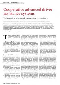
Robot 2 with 6 DOF
• •
Carrying client satellite mock-up Motion simulation of client satellite
PC-based real-time facility control system Robot 1 with 6 DOF on a 25 m rail system
• •
Carrying RV sensors and docking system of servicing satellite Motion simulation of servicing satellite
Fig.2 The new EPOS facility: robotics-based testbed (left) and a hardware overview (right)
rail system mounted on the floor to move an industrial robot up to a distance of 25m, KUKA KR100HA robot (robot 1) mounted on the rail system for simulating the 6 degree of freedom of one spacecraft, KUKA KR240 robot (robot 2) mounted at the end of the rail system for simulating the 6 degree of freedom of the second spacecraft, PC-based monitoring and control system to monitor and control the RvD simulation.
Control Concept The entire control system can be divided into three levels (see Fig. 3): the Local Robot Control (LRC) system, the Facility Monitoring and Control (FMC) system, the Application Control System (ACS). Regarding the HW items, each robot is independently controlled in real-time by its own LRC unit, provided by the robot manufacturer. At the FMC level the entire facility is controlled and monitored in real-time. Moreover, the FMC system allows the following tasks: operator’s monitoring action over all the parameters and states of the facility, logging of all the parameters and states of the facility, including external synchronization signals, real-time control of the entire facility including synchronization of all motion devices and kinematical conversions of the external commands, choice among different interfaces (IF). The following options are available: o a synchronous IF (EtherCAT), for closed-loop applications, o an asynchronous IF, in order to run a predefined trajectory stored in a file, o a KUKA Robot Sensor IF (RSI) to directly interface the FMC with the LRC units. Finally, at the ACS level, the actual application of the dynamic system is run. In particular, the models of the satellites dynamics and the case-specific scenarios can be implemented in a MATLAB/Simulink environment. This means that the whole software related part of the simulation can exploit a modelbased design approach. According to it, MATLAB/Real-Time Workshop can be used to accomplish the automatic code generation. Subsequently the real-time executable is downloaded to a target platform running under the VxWorks operating system. The desired motion commands must be sent every 4ms to the facility, as requested by the LRC units.
SESP 2012: Simulation and EGSE facilities for Space Programmes
3
ESTEC ~Noordwijk 25-27 September 2012
Tab. 1 EPOS motion capabilities [9]
RvD Sensors etc.
Level 1: ACS Application Control System
ACS/MMI
ACS/RT
Windows
VxWorks Slave
Ethernet
EtherCAT Master
Level 2: FMC
FMC/MMI
FMC/RT
Windows
VxWorks
Facility Monitoring and Control System RSI
KRC 1
KRC 2
Level 3: LRC Local Robot Control Units
Robot 1
Robot 2
Parameter Position: X Y Z Roll Pitch Yaw Velocity (Trans., Rot.): Acceleration (Trans./Rot.): Position accuracy [3D/3 σ ] (Trans./Rot.): Payload: Command rate:
Robot 1
Robot 2
-2,5 - +24,5m -2,5 - +2,5m -2,5 - +2,5m -1,0 - +4,0m -0,5 - +1,5m -0,5 - +1,2m -300 - +300deg -90 - +90deg -90 - +90deg 2m/s , 180deg/s 2.3m/s² , 100deg/s²