Using RuleML for Representing and Prolog for Simulating Fuzzy Cognitive Maps Athanasios Tsadiras 1and Nick Bassiliades 2
Abstract Fuzzy Cognitive Map (FCM) technique is broadly used for decision making and predictions by experts and scientists of a wide range of disciplines. The use of the FCMs would be even wider if a standardized representation of FCMs was developed and a system that would simulate them was constructed. Having such a system, decision makers would be able to create and examine their own developed Fuzzy Cognitive Maps, and also distribute them e.g. through Internet. In this chapter, a) we propose a RuleML representation of FCMs and b) we present the design and implementation of a system that assists experts to simulate their own FCMs. This system, which is developed using the Prolog programming language, makes the results of the FCM simulation directly available to other cooperative systems because it returns them in standard RuleML syntax. In the chapter, the design choices of the implemented system are discussed and the capabilities of the RuleML representation of FCM are presented. The use of the system is exhibited by a number of examples concerning an e-business company.
1 Introduction Scientists from various disciplines are using Fuzzy Cognitive Map (FCM) as a method for taking decisions and making predictions. To take decisions through FCM, the simulation of the FCM model is required. This can be is a difficult task, especially from those scientists that do not have the required computer skills. Furthermore, the degree of expertise of the domain experts involved in the FCM construction is vital for the successful construct of an FCM.
Athanasios Tsadiras Department of Economics, Aristotle University of Thessaloniki, GR-54124 Thessaloniki, Greece e-mail:
[email protected] 2Nick
Bassiliades Department of Informatics, Aristotle University of Thessaloniki, GR-54124 Thessaloniki, Greece e-mail:
[email protected]
2
In this chapter we try to cope with the following problems that FCMs face at the present time: 1. There is no standard representation of FCMs that would make them easily reusable and transportable. 2. There is no standard software that would simulate FCMs. Nowadays every scientist has to create his own software system. 3. No repository of FCMs exists to assist their dissemination. In the chapter, these problems are handled by developing: 1. an XML representation of FCMs, which is based on RuleML [2], a popular rule interchange format for the web, 2. a Prolog-based simulation system that can assist FCM authors to simulate their scenarios in FCMs. The basic assumption that we make is that FCMs closely resemble rules, since they represent causality relations between concepts, something that matches with the logical implication semantics of rules. In the Section 2 of this chapter, a short introduction to FCMs and related literature is given. Section 3 discusses the representation capabilities of RuleML while Section 4 presents the proposed RuleML representation of FCMs. Section 5 explains the design of the Prolog-based simulation system that simulates FCMs represented in RuleML. Section 6 concerns the implementation and demonstration of the system’s capabilities. Finally, conclusions and recommendations for further research are presented in Section 7.
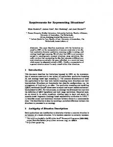
2 Fuzzy Cognitive Maps and Related Literature Kosko introduced in 1986, Fuzzy Cognitive Maps (FCMs) [15-16], based on Axelord's work on Cognitive Maps [1]. FCMs are considered a combination of fuzzy logic and artificial neural networks and many researchers have made extensive studies on their capabilities (see for example [12, 13, 19, 21, 22]). An example of an FCM concerning an e-business company (modified version of the model presented in [8]), is given in Fig.1. In this figure, the nodes represent the concepts that are involved in the FCM model and the directed arcs between the nodes represent the causal relationships between the corresponding concepts. Each arc is accompanied by a weight that defines the type of the causal relation between the two nodes. A positive (negative) causal relation between two concepts C i and C j means that an increase of the activation level of concept C i will increase (decrease) C j and also a decrease of concept C i will decrease (increase) C j .
3
C1 E-Business Profits C7
0.9
C2
0.9
Better ECommerce Services
E-Business Sales
0.9 -0.7
0.2
-0.4
0.7
C6
0.8
C3
Impact from International EBusiness Competition
Prices Cutoffs -0.3 0.7
0.7
0.8 -0.3
C4
0.8
-0.5 -0.2
Customers' Satisfaction
C5
Staff Recruitments
Fig. 1 An FCM concerning an imaginary e-business company (modified version of the model presented in [8]).
The level of activation of each concept Ci at time step t is determined by number A it , i=1,...,n with n to be the number of concepts of the FCM. The weight of the arc that connects Ci and C j is defined as w ij . The FCM system is updating in a synchronous manner which means that A it +1 , i=1,...,n is calculated by one of the following formulas: 1. Ait +1 = f M ( Ait , Sit )- d Ait using Certainty Neurons [22] or 2. Ait +1 = f M (w1i A1t ,f M (w2i A2t ,f M (...,f M (wn −1,i Ant −1,wn,i Ant )))) - dAit
(1) (2)
using Recursive Certainty Neurons [23] where, • S t = w At is the sum of the weight influences that concept Ci receives at ∑ ji j i j
time step t from all other concepts, • d is a decay factor and •
A t + S t (1 − A t ) = A t + S t − S t A t i i i i i i i f M (A it , Sit ) = A it + Sit (1 + A it ) = A it + S it + S it A it (A it + S it ) 1 − min( A it , S it )
(
)
if A it ≥ 0, Sit ≥ 0 if A it < 0, S it < 0 A it , S it ≤ 1 if A it S it < 0
(3)
4
is the function that was used for the aggregation of certainty factors at the MYCIN expert system [4]. Many attempts have been made recently in order to develop methods for training and learning of FCMs [17, 18, 20]. Despite that, the development of a commonly used tool that can assist the creation and simulation of FCMs remains crucial because of the application of FCM technique to a wide variety of scientific areas. Attempts that have been done towards the creation of such a tool are the following: • FCM Constructor is a knowledge acquisition system that builds an FCM by direct knowledge acquisition [6]. • The FCM Designer Tool is a tool in Spanish which allows the design of the structure of the FCMs [10]. The tool handles casual relationships as rules. • FCMapper is an FCM analysis and visualization tool based on MS Excel (http://www.fcmappers.net/). • The Fuzzy Cognitive Map applet is an on line calculator and downloadable Java application for FCM computations (http://www.ochoadeaspuru.com/fuzcogmap/index). • A Java standalone library for FCM computations exists in http://jfcm.megadix.it/. • FCModeler tool is a Java interface that reads and displays data from an Excel spreadsheet of links and nodes [7]. An FCM tool should also facilitate knowledge sharing and reuse of knowledge in order to deal with semantic interoperability between different systems. Attempts towards this point are the following: • Jung [11] proposed ontological Cognitive Maps (ontoCM) as an extension to Cognitive Maps that additionally provides semantic information by ontology that is organized on a tree-like hierarchical structure. • Carvalho [5] studied the semantics of FCMs for the modeling and simulation of complex social, economic and political systems. In our study, we propose the use of RuleML for the representation of FCM that promotes interoperability between different systems and reuse of knowledge.
3 Representing Capabilities of RuleML The Rule Markup Language (RuleML) is a markup language designed for the interchange of various types of Web rules in an XML format that is uniform across various rule languages and platforms [2]. RuleML was developed to express both forward (bottom-up) and backward (top-down) rules in XML for deduction, rewriting, and further inferential-transformational tasks. The specification
5
of RuleML constitutes a modular hierarchical family of Web sublanguages, whose root accesses the language as a whole and whose members identify customized, combinable subsets of the language. Each of the family’s sublanguages has an XML Schema definition, addressed by a URI, which permits inheritance between sublanguage schemas and precise reference to the required expressiveness. Logic rules are in the form A→Β, whereas A is called antecedent or condition of the rule, while B is the consequent or the conclusion of the rule. The usual semantics of a rule is that whenever the condition is true, then the conclusion is also true. In other words, the existence of the antecedent causes the existence of the consequent (assuming that existence of something in an e.g. database is equivalent to being true). An FCM consists of factors (concepts / nodes) which represent the important elements of the mapped system. The strength of the causal relationships between the factors is determined by the directed weighted arcs. Consequently, it is natural to think of rules as a way to represent these causal relationships between concepts. Other scientists also followed this idea, e.g. the FCM system of Jose & Contreras [10], handles casual relationships as rules.The concept nodes are equivalent to things being true, whereas the directed arc is equivalent to the implication operation of a rule between the concepts. For this reason, we have chosen a rule-based representation of FCMs as a basis for a standard representation language. Moreover, we have chosen RuleML, a defacto web rule standard, as a candidate language for representing and exchanging FCMs on the Web. The latest version 1.0 of the RuleML standard is employed, coupled with an additional controlled vocabulary in order to cover all the representational requirements of FCMs. This is detailed in the next section.
4 Representation of FCMs using RuleML In this section we present how FCM causal relationships can be represented as rules in RuleML. The presented representation is an improved representation of that presented in [25]. An FCM contains a number of arcs that represent causal relationships between its concepts, as it can be seen in Fig. 1. All these relationships have the following form: Concept1 “influences” Concept2 “with weight” W. These FCM causal relationships can be represented in RuleML as rules. In RuleML1.0 3, the above abstract relationship can be represented as follows: 3
http://ruleml.org/1.0/
6 Concept1 W Concept2
It can be noticed that such rules are in propositional logic because the atoms in RuleML are not needed to have arguments, since concepts in FCM are atomic with no parameters. For example, the arc in Fig. 1 between concepts C2:“E_Business Sales” and C4:“Customer Satisfaction” with weight 0.2, presents the following causal relationship: E_Business Sales influences Customers Satisfaction with weight 0.2. It can be represented by the following RuleML rule: e_business sales 0.2 customers satisfaction
Of course, we need a RuleML rulebase with N rules as the above, in order to represent a complete FCM with N arcs/causal relationships. Moreover, for the representation of an FCM statements like the following are required: Concept “is set to” Value. Such statements mean that the activation level of the specific concept should be kept steady to that certain value through the whole simulation process. In RuleML, such statements can be represented as facts about concepts referred to by rules, in the following manner: Value
7 Concept
For example, according the above, to represent in RuleML that “E-Business Sales are set to 0.3” or “E-Business Sales are set to low”, the following RuleML code is needed. 0.3 e_business sales
low e_business sales
A similar representation is required in FCM, for statements like the following: Concept “is initially set to” Value. Statements like the above mean that the activation level of the specific concept initially (at time step 0) is set to the specific value and afterwards, the concept is free to interact with other concepts and to change this value accordingly. In RuleML such statements can be presented again by facts, augmented with an additional “system” modifier argument whose value is the constant “dynamic” from the controlled vocabulary for FCMs. Value Concept
So for example, to represent in RuleML that “E_Business Sales are initially set to 0.8” or “E_Business Sales are initially set to high”, the following RuleML code is needed. 0.8
high
e_business sales
e_business sales
Other parameters of FCM that must be specified are:
8
1. the type of transfer function that should be used through the simulation (either the mycin function for eq. (1) or the recursive function for equation (2) ), 2. the value of the decay factor d, In order to represent these global simulation parameters in RuleML, a relative “system” modifier fact is created containing the required information. This atom is of the form: TRANS_FUN DECAY_VALUE
where TRANS_FUN is either mycin or recursive and DECAY_VALUE is a decimal between 0 and 0.5. For example: mycin 0.1
Notice that the operator of the “system” fact is defined in the controlled vocabulary for FCMs. The name of the transformation function though is not within the controlled vocabulary in order for the RuleML representation for FCMs to be extensible and adaptable to any FCM simulator system and not to be restricted to the specific transformation functions of our system. Having defined the above representation of FCM in RuleML, the FCM of Fig. 1 can be presented as it appears in Fig. 2: mycin 0.1
9 e_business profits 0.9 e_competition …. 0.3 staff recruitments 0.5 e_competition
Fig. 2 RuleML representation of FCM shown in Fig. 1.
The controlled vocabulary for FCM is minimal, consisting of one system relation name and one constant only. The mechanism for handling controlled vocabularies in RuleML is open to the application. We have chosen to represent the vocabulary using RDF/RDFS as it is shown below.
10
Notice that the relation name is equivalent to an RDFS class, whereas the constant name is an instance of the generic rdfs:Resource class. If we had named slots in the controlled vocabulary for the FCMs, we would have also used RDF properties.
5 Design of the RuleML-FCM simulation system Having represented the FCM in RuleML, the next step is that of simulating the represented FCM. The stages for the simulation of scenarios imposed to FCMs, are shown in Fig. 3.
USER
RuleML file
FCM.xslt file
XML Processor
RuleMLFCM System
Stage 1
“stage1_output.pl” file
FCM Simulation in Prolog
Stage 2
Output text file of simulation data
On screen results of FCM simulation
Output
USER Ruleml Output file
Input
Fig. 3 Stages for the simulation of FCM represented in RuleML In Stage 1 of the simulation system a) the RuleML file that represents the FCM and b) the XSLT file of Fig. 4, are inputted to an XSLT processor which performs an XSL transformation and produces at the output, a Prolog file having statements of the forms shown in Fig. 5.
11 with_weight(influences(,), ). use(). decay_is_set_to(). initially( is_set_to( , ). [ , ]
Fig. 4 XSLT file for transforming the RuleML representation to a textual FCM representation for the simulation of FCM.
with_weight(influences( Concept1_name_in_list_form , Concept2_name_in_list_form , Weight ). is_set_to( Concept_name_in_list_form , Weight ). initially(Concept_name_in_list_form , Weight ). use( mycin/recursive ). decay_is_set_to( Value ). Fig. 5 RuleML Generic Prolog statements of the XSLT transformation.
In the statements of Fig. 5: • “Concept_name_in_list_form” is a list of one or more words. • “Weight” is either a number in the interval [-1,1], or a linguistic value such as “very low”, “low”, “average”, “high” and “very high”. These linguistic values during the next phase of our system will be translated to the values 0.1, 0.3, 0.5, 0.7, 0.9, respectively. • “Value” of the decay factor is a numerical value in the interval [0, 0.5]. Using the above transformation in Stage 1, the RuleML representation of the FCM of Fig. 2 is transformed to that shown in Fig. 6. These statements will be
12
saved to a “stage1_output.pl” file and automatically is inputted to the Prolog subsystem of FCM simulation. use(mycin). decay_is_set_to(0.1). with_weight(influences( [e_business,profits] , [e_competition] ), 0.9). with_weight(influences( [e_business,sales] , [e_business,profits] ), 0.9). …. with_weight(influences( [e_competition] , [staff,recruitments] ), 0.8). with_weight(influences( [better,e_services] , [customers,satisfaction] ), 0.9). is_set_to( [staff,recruitments] , 0.3). initially( [e_competition] , 0.5).
Fig. 6 Content of the “stage1_output.pl” file containing the transformation of the RuleML representation of the FCM shown in Fig. 1, in Prolog statements.
The simulation of the FCM is performed in Stage 2 of the system (see Fig. 3), by a program written in the Prolog programming language [3]. An earlier version of this application is presented in [25]. FCM can reach a) an equilibrium point, b) a limit circle periodical behaviour or c) a chaotic behaviour [24]. If an equilibrium point is reached, as shown in Fig. 3, 1. the activation levels of all FCM’s concepts at equilibrium are shown on the computer screen, 2. these activation levels are saved to an output file in a RuleML format as a set of facts, to make them available for use by other systems and 3. the activation levels of the concepts of the FCM model through the transition phase towards this equilibrium point are saved as output data into an text file called “fcm_simulation_output.txt”, for possible further examination. If the FCM reaches a limit circle behaviour or a chaotic behaviour then the system simulates 10,000 time steps of interaction and saves the activation levels of the concepts of the FCM model through these 10,000 time steps to the “fcm_simulation_output.txt” file for further examination by a graph plotting software tool.
6 Demonstration of the RuleML-FCM Simulation System The RuleML-FCM simulation system is implemented in SWI-Prolog (http://www.swi-prolog.org/), following the design described in the previous section. To demonstrate its implementation, the FCM of Fig. 1 will be used, in which “staff recruitment” is set to 0.3. This scenario (let’s call it scenario #1) attempts to predict the consequences of a small increase to the number of employees of the ebusiness company. To examine this scenario, the RuleML representation of FCM
13
of Fig. 1 (as shown in Fig. 2) is saved to a file called “FCM for ebusiness.ruleml” and inserted to the RuleML-FCM system together with the “fcm.xslt” file of Fig. 4. The output of the system is shown in Fig. 7.
Fig. 7 Output of RuleML - FCM simulation system for an FCM concerning an e-business. Scenario #1: “staff recruitments” is set to 0.3. Equilibrium reached after 77 time steps.
Seven (7) different concepts are identified and one of them, concept “staff recruitment”, is set constant to 0.3. After 80 time steps, FCM reaches an equilibrium point to the state that is presented in Fig. 7. From that, we can conclude that the small increase to the number of employees (0.3), leads to a significant increase to competition from other companies (0.57171). This causes a significant decrease to prices (prices cutoffs=0.64366) that leads to a significant increase to sales and profit of the ebusiness company (e_business sales=0.74063 and e_business profits=0.54083). The satisfaction of the customers is increased (0.72229). The small increase to the number of employees (0.3), did not cause to any change to the
14
quality of the offered e-services (better e_services=-0.02948) because of the large increase to the number of sales. The data of the interactions during the 77 time steps are saved to an output text file. This file can be processed by a graph plotting software tool and the transition phase towards equilibrium can be exhibited. This transition phase for the case above is shown in Fig. 8. Additionally, a RuleML output file is created, as shown in Fig. 9, containing the activation levels of all FCM’s concepts at equilibrium point, represented as RuleML facts. This facilitates the use of FCM’s results by other systems, using the common RuleML representation.
Fig. 8 RuleML Transition phase towards equilibrium for scenario #1. 0.72229 customers satisfaction -0.02948 better e_services … …
15 0.54083 e_business profits
Fig. 9 RuleML output file representing the activation levels of FCM’s at equilibrium for scenario #1.
Other “what-if” scenarios can be studies with the system, in order the decision maker to examine the predicted outcomes according to the FCM. In this new scenario #2, we would like to predict the consequences of a small decrease of the number of employees of the e-business company (instead of a small increase which was the case in scenario #1). To simulate this scenario, concept “staff recruitment” is set constant to value “-0.25”. Running this new scenario #2, the outcome is that of Fig. 10.
Fig. 10 Output of RuleML - FCM simulation system. Scenario #2: Staff recruitments is set to 0.25. Equilibrium found after 80 time steps.
Once again seven (7) different concepts are identified, and one of them, concept “staff recruitment”, is set constant to -0.25. After 80 time steps, FCM reached an equilibrium point, with the concepts to be activated to the degree shown in Fig.
16
10. It can be concluded that according to the FCM predictions, the small decrease of the number of employees leads to a decrease of the quality of the provided eservices (better e-services= -0.55947). The company reacts with severe discounts (prices cutoffs= 0.71308) that cause significant increase in sales and profits (ebusiness sales=0.60919 and e-business profits=0.63818). A small increase of customers satisfaction is predicted (customer satisfaction is 0.34806) while competition is significantly increased (e-competition= 0.62097). A RuleML output file is created, containing the activation levels of FCM’s concepts at equilibrium. Additionally, an output text file is created, containing the data of the interactions during the 80 time steps. Based on this data, Fig. 11 is created.
Fig. 11 Transition phase towards equilibrium for scenario #2.
Another scenario (scenario #3) is tried with the system, to examine the consequences of a more severe decrease of the number of the e-business employees, than that of scenario #2. In scenario #3, the concept “staff recruitment” is set constant to value “-0.5” (instead of -0.25 of scenario #2).Running this scenario in the system, the outcome is that of Fig. 12. As it is shown in that figure, after 114 time steps, FCM reached an equilibrium point, with the concepts to be activated to the degrees shown in Fig. 12. It can be concluded that according to the FCM predictions, that the severe decrease to the number of employees causes serious problems. The quality of the provided e-services is decreased (better e_services= 0.33472) and the same applies for e-competition (-0.59306). Prices are increased (prices cutoffs=-0.59306), leading to severe decrease in sales and profits (ebusiness sales=0.75698 and e-business profits=0.4687). The transition phase according to the data of the output file is shown in Fig. 13. A RuleML output file is also created, containing the activation levels of FCM’s concepts at equilibrium.
17
Fig. 12 Output of RuleML - FCM simulation system. Scenario#3:“Staff recruitments” is set to 0.5.
Fig. 13 Transition phase of an FCM concerning a car industry for scenario #3.
To examine the effect of an increase to the prices, scenario #4 is imposed to the system. According to this scenario, “prices cutoffs” is decreased to a degree of 0.3. The output of the systems for this scenario, is that of Fig. 14. After 167 time steps, (as it is shown in Fig. 14) FCM reached an equilibrium point, with the concepts to be activated to the degrees shown in Fig. 14. According to the FCM predictions, this is very bad scenario for the company. Even this small increase in
18
prices leads to severe decrease in sales and profits (e-business sales= -0.67154 and e-business profits= -0.40533). The quality of the provided e-services is decreased and customers satisfaction is severely decreased. A decreased of the number of employees and e-competition is predicted (staff recruitments= -0.66884, ecompetition= -0.55538). According to the data of the output file, the transition phase is that of Fig. 15. Similarly to the previous scenario, a RuleML output file is created, containing the activation levels of FCM’s concepts at equilibrium .
Fig. 14 Output of RuleML - FCM simulation system. Scenario#4:“prices cutoffs” is set to -0.3.
Fig. 15 Transition phase of the FCM for scenario #4. Equilibrium reached after 167 time steps.
19
The RuleML-FCM system can also examine scenarios in which one or more weights of the connections between the FCM’s concepts are changed. For example, lets create another scenario (scenario #5), which is similar to scenario #4 (“prices cutoffs” is set to -0.3.) but in scenario #5 the weight of the influence of “price cutoffs” to “customers satisfaction” is 0.4, instead of 0.7 that is in scenario#3. In other words, scenario #5 examines how scenario #4 is affected by a change of the strength that “price cutoffs” influences “customers satisfaction”. This scenario is imposed to the system and the outcome is that of Fig. 16. No equilibrium point is reached after 10,000 iterations. To examine the dynamical behaviour of this scenario, Fig. 17 is created based on the data of the output file. It is apparent that the FCM enters a limit cycle behaviour where all concepts periodically are getting high and low. For the e-business company, it can be concluded that these concepts will continuously increase and decrease, meaning that there will be strong interactions and no equilibrium for this scenario.
Fig. 16 Output of RuleML - FCM simulation system. Scenario#5: “prices cutoffs” is set to -0.3. “price cutoffs” influences “customers satisfaction” with weight 0.4 (instead of 0.7 that is in scenario#4).
Fig. 17 Transition phase of the FCM for scenario #5. Limit cycle behaviour is reached.
20
For the e-business company, scenario #5 is better than scenario #4 because the outcome of scenario #4 is very bad while scenario #4 products strong interactions between of the concepts of the FCM but not a equilibrium to a bad position for the e-business company. It is interesting to notice that the results of the same action (increase in prices) can lead to different outcome, even when a single interaction in FCM is changed (weight between “price cutoffs” and “customers satisfaction” in the above case). This indicates that: 1. Experts should be very careful when they create an FCM. 2. Decision makers, by using FCMs, can also be supported in their decisions by examining scenarios that involve the change of the weights between the interactions of the FCM’s concepts. 3. Decision makers can also use results of FCM’s scenarios in order to examine what structural changes should strategically be done, in order to reach the desired results. More scenarios can be created and the predicted outcome will be immediately received. This is highly appreciated by decision makers that are willing to examine a number of “what-if” scenarios and check the predicted consequences of these scenarios.
7 Conclusions In this chapter, a RuleML representation of FCMs is proposed that make FCMs: • reusable and transferable, • ready to interact with other systems that interact with RuleML, • easily managed within a repository, that is important for FCM researchers and practitioners. Additionally, a program written in Prolog is designed and implemented which: • Simulate scenarios written in the form of the RuleML representation of FCM. • Present the equilibrium point of the imposed scenario. • Produce a RuleML output file that contains the activation levels of FCM’s concepts at equilibrium. • Produce an output file that contains the data of the transition phase to visualize it, if the user wants to. The use of the system above is illustrated using a number of examples, to prove its utility for decision makers working with FCMs. It was found that: • The representation of FCMs in RuleML is simple, given that numerous userfriendly XML editors exist. • No programming skills are required to create and simulate FCMs.
21
• A number of different scenarios can be examined rapidly and easily, having the decision maker focused on the FCM itself and not to computer technicalities. In the future we would like to work towards a) the development of a userfriendly editor for building FCMs, such as a natural language interface to feed directly the Prolog simulator (e.g. in ACE [9]), and/or a graphical/visual RuleMLware editor, as in [14], b) the integration of the various functionalities of the system into a single stand-alone web application that will help disseminate FCM research and development.
References 1. Axelrod, R.: Structure of Decision, Princeton University Press (1976). 2. Boley, H.: The RuleML Family of Web Rule Languages. In: Alferes, J.J., Bailey, J., May, W., Schwertel, U. (eds.) PPSWR 2006. LNCS, vol. 4187, pp. 1–17, Springer, (2006). 3. Bratko I.: Prolog–Programming for Artificial Intelligence, Addison Wesley, 3rd edition (2000). 4. Buchanan, B. G. & Shortliffe E. H.: Rule-Based Expert Systems. The MYCIN Experiments of the Stanford Heuristic Programming Project, Addison-Wesley (1984). 5. Carvalho, J.P., On the semantics and the use of fuzzy cognitive maps and dynamic cognitive maps in social sciences, Fuzzy Sets and Systems 214 6-19 (2013). 6. Cheah, W.P., Kim, Y.S., Kim, K.Y, Yang, H.J.: Systematic causal knowledge acquisition using FCM Constructor for product design decision support, Expert Systems with Applications 38(12) 15316-15331 (2011). 7. Dickerson, J.A., Berleant, D., Cox, Z., Qi, W., Wurtele, E.: Creating Metabolic Network Models using Text Mining and Expert Knowledge, Atlantic Symposium on Molecular Biology and Genome Information Systems and Technology (CBGIST 2001), Durham, North Carolina (2001). 8. Eberhart, R.C., Dobbins, R.W.: Neural Network PC Tools, Academic Press (1990). 9. Fuchs, N.E. , Kaljurand, K., Schneider, G.: Attempto Controlled English Meets the Challenges of Knowledge Representation, Reasoning, Interoperability and User Interfaces, FLAIRS Conference 2006, 664-669 (2006). 10. Jose A., Contreras J.: The FCM Designer Tool in “Fuzzy Cognitive Maps”, Studies in Fuzziness and Soft Computing 247 71-87 (2010). 11. Jung, J.J.: Semantic annotation of cognitive map for knowledge sharing between heterogeneous businesses, Expert Systems with Applications 39 5857–5860 (2012). 12. Khan M.S., Chong A., Gedeon T.: A Methodology for Developing Adaptive Fuzzy Cognitive Maps for Decision Support, Journal of Advanced Computational Intelligence, 4(6) 403-407 (2000). 13. Khan, M. S., Quaddus, M.: Group Decision Support Using Fuzzy Cognitive Maps for Causal Reasoning, Group Decision and Negotiation 13 463–480 (2004). 14. Kontopoulos, E., Bassiliades, N., Antoniou, G., Seridou, A.: Visual Modeling of Defeasible Logic Rules with DR-VisMo, International Journal of Artificial Intelligence Tools 17(5) 903924, (2008). 15. Kosko, B.: Fuzzy Cognitive Maps, Inter. Jour. of Man-Machine Studies, 24 65-75, (1986). 16. Kosko, B.: Neural Networks and Fuzzy Systems, Prentice-Hall (1992). 17. Papageorgiou, E.I.: Learning Algorithms for Fuzzy Cognitive Maps-A review study, IEEE Transactions on Systems Man and Cybernetics (SMC)-Part C 42 (2) 150-163 (2012).
22 18. Papakostas G.A., Koulouriotis D.E., Polydoros A.S., Tourassis V.D.: Towards Hebbian learning of Fuzzy Cognitive Maps in pattern classification problems, Expert Systems with Applications 39(12) 10620-10629 (2012). 19. Stach, W., Kurgan, L., Pedrycz, W., Reformat, M.: Genetic learning of fuzzy cognitive maps, Fuzzy Sets and Systems 153(3) 371-401 (2005). 20. Stach, W., Pedrycz, W., Kurgan, L.A.: Learning of fuzzy cognitive maps using density estimate, IEEE Transactions on Systems, Man, and Cybernetics, Part B: Cybernetics42(3) 900912 (2012) 21. Taber, R., Yager, R. R., Helgason, C. M.: Quantization effects on the equilibrium behavior of combined fuzzy cognitive maps, International Journal of Intelligent Systems 22(2) 181-202 (2006). 22. Tsadiras, Α. Κ., Margaritis, K. G.: Cognitive Mapping and Certainty Neuron Fuzzy Cognitive Maps, Information Sciences 101 109-130 (1997). 23. Tsadiras, Α.Κ., Margaritis, K.G.: Recursive Certainty Neurons and an Experimental Study of their Dynamical Behaviour, Proceedings of the European Congress on Intelligent Techniques and Soft Computing (EUFIT ’97), Aachen, Germany, 510-515 (1997). 24. Tsadiras, Α.Κ., Margaritis, K.G.: An Experimental Study of Dynamics of the Certainty Neuron Fuzzy Cognitive Maps, NeuroComputing 24 95-116 (1999). 25. Tsadiras A.K., Bassiliades N.: RuleML Representation and Simulation of Fuzzy Cognitive Maps, Expert Systems with Applications40 1413–1426 (2013).