Int. J. Pure Appl. Sci. Technol., 12(1) (2012), pp. 39-48
International Journal of Pure and Applied Sciences and Technology ISSN 2229 – 6107 Available online at www.ijopaasat.in Research Paper
Using Simulation Modelling to Improve the Performance of Chemical Engineering Processes: Part 1 – Industrial Heat Exchanger Network Analysis Kenneth Kekpugile Dagde1,* and Beabu Kiasira Piagbo2 1
Department of Chemical/Petrochemical Engineering, Rivers State University of Science and
Technology, Port Harcourt, PMB 5080, Port Harcourt, Rivers State, Nigeria 2
School of Science and Engineering, Teesside University Middlesbrough, TS1, 3BA, United Kingdom
* Corresponding author, e-mail: (
[email protected]) (Received: 1-8-12; Accepted: 4-9-12)
Abstract: Heat exchanger network synthesis is a widely studied field in process integration research due to the growing concern for safe and efficient energy systems. Though widely applied in the grassroots design, synthesis solution methodologies can also be applied to existing heat exchanger networks to ascertain the energy saving options available for such poorly designed networks. This research uses monitored industrial plant data with the aid of Aspen Energy Analyser® to analyse the heat exchanger network of the crude distillation unit of a refinery in Port Harcourt, Niger Delta region of Nigeria, West Africa. The analyses showed that the heating and cooling value were above the target by 5.52*107KJ/h due to cross pinch heat exchangers. This represents 71.15% and 25% above target value for the heating and cooling load respectively. Also, the number of heat exchanger units and number of shells is above the target value by 84.62% and 92.31% respectively. Thus a retrofit operation is recommended for the heat exchanger network.
Keywords: Heat Exchanger Network Synthesis, Cross pinch, Minimum Approach Temperature, Driving Force Plot.
Int. J. Pure Appl. Sci. Technol., 12(1) (2012), 39-48.
40
1. Introduction: Simulation modelling is one of the widely used operations research and management science techniques. It is among the first three techniques, the other two being “Math Programming” and statistics [1]. It has been applied in computer networks, services and health sector, management and engineering. Simulation modelling refers to various techniques used in the study of the behaviour of real systems [2]. Simulation provides data for system validation and improving the design of a system with respect to both qualitative and quantitative processes. It is very useful in “what if” scenario analysis, thus alternative solutions can be generated to obtain the best solution. Simulation models with time parameters provide information on the performance of the system. For chemical engineering process as well as other business process projects, simulation modelling can be used to improve the performance of the process with regard to time, cost, and general performance. After the energy crisis in the 1970s the emphasis has been on efficient and effective saver energy designed systems. This concern has of late been aggravated by the global environmental awareness and concern for global warming and its detrimental impact on the environment [3]. Refinery operations are capital intensive and involve the use of much energy. Because of the rising cost of energy, chemical companies, refineries and petrochemical companies continue to look for ways to decrease energy consumption through process integration. Heat integration involves simulation of the process with real industrial plant data, collecting the simulated data and applying heat integration techniques to reduce the quantities of utilities that are not necessary in the process. Heat Exchanger Network Synthesis is a very important field in Process System Engineering. It is the most studied field in process integration due to its role in controlling the cost of energy for a process [4]. A thorough and comprehensive literature review on Heat Exchanger Synthesis has been done by [5, 6, 7, and 4]; the reader may refer to these journals for more understanding of the subject. Heat exchanger network synthesis solution techniques can either be sequential synthesis techniques or simultaneous synthesis techniques. The sequential synthesis techniques is further divided into (1) Evolutionary design techniques such as pinch design technique [8, 9, and 10]; dual temperature techniques [11]; pseudo-pinch techniques [12]; and block decomposition techniques [13, 14], and (2) Mathematical Programming techniques based on the continuous and integer linear programs [15,16]. The simultaneous synthesis techniques seek to find the optimal network without decomposition of the problem. They are primarily Mixed Integer Non Linear Programming (MINLP) formulation of heat exchanger problems subject to various simplifying assumptions used to facilitate the solution of these complex models [17, 18, 19]. With the advent of digital computers and its wide application in the solution of Chemical Engineering problems, most of these solution techniques have been developed into computer packages. Aspen Energy Analyser® developed by Aspen Technologies Ltd is one of such solution software packages. It combines pinch technology and mathematical programming in the synthesis of heat exchanger networks. This work uses industrial data from a typical refinery in Port Harcourt Nigeria with the aid of Aspen Energy Analyser® to analyse the heat exchanger network of the preheat section of the crude distillation unit of the refinery, in order to explore the energy and cost saving opportunities available to the refinery. This is necessary because industrial equipment stocks in Nigeria were imported during the era of cheap energy and before the advent of the heat integration techniques in vogue today [20].
2. Material and Method: 2.1. Process Mapping: A process map of the refinery is shown in Figure 1.
Int. J. Pure Appl. Sci. Technol., 12(1) (2012), 39-48.
41
Figure 1: Process Map [21] The heat exchanger synthesis problem includes 11 process streams – 3 cold streams and 8 hot process heating streams. The cold streams are heated by 24 heat exchangers from a temperature of about 29.9OC to 344OC before it enters the distillation column where the components are separated. The cold streams include the crude from storage stream, the desalted crude stream, and the pre-flashed crude stream. 8 hot process to process streams are used to preheat the cold streams, these includes atmospheric residue, stripped kerosene, stripped Light Diesel Oil (LDO), stripped Heavy Diesel Oil (HDO), Heavy Vacuum Gas Oil (HVGO), and the 3 Pump Around streams – Top Pump Around, Kerosene Pump Around, and LDO Pump Around [21]. The basic information needed for the simulation - the inlet and outlet temperature of the process and utility streams, and the enthalpy or heat capacity value of the streams, and the flow rate of the process streams, were obtained from the process flow diagram and the operating data of the crude distillation unit of the refinery. The process streams and utility streams data were extracted correctly taking in to consideration basic data extraction principles such as – avoiding mixing of the streams at different temperatures; extracting streams on the safe side; segmenting streams with varying enthalpies; and not extracting true utility streams that can be replaced by other streams [22]. The specific heat capacity of petroleum products were calculated using the empirical formula: (1) where is the specific gravity of the petroleum product at the specific heat .
,
is the temperature in
, and
is
Since the flow rates of the process streams are expressed in volumetric flow rates, these were converted to mass flow rates by using the relationship: (2) The extracted process streams and utility streams data was later imputed into Aspen Energy Analyser® for the analysis of the heat exchanger network. Table 1 and 2 show the process streams and utility streams data obtained from the process flow diagram and operating data of the Crude Distillation Unit obtained from the refinery.
Int. J. Pure Appl. Sci. Technol., 12(1) (2012), 39-48.
42
Table 1 Extracted Process Streams Data [21] Process Stream Data Inlet Outlet Flow Temp Temp Density rate (0C) (0C) (Kg/m3) M3/hr 96.7 788 747 152.4 226.3 184 833 451 184 154.9 833 451 152 278.7 233.6 858 828 96 227.9 168 35.6 828 96 168 280 207 863 158 158 207 38.9 863 898 18 316 65.6 944 150 328 204 204 164 944 150 164 95.4 944 150 927 10 241 222 134.9 841 310 29.9 212 841 306 134 529 212 344 841 Table 2 Utility Streams Data [21]
Name Top Pump Around Kerosene Pump Around LDO Pump Around Stripped Kerosene Stripped LDO Stripped HDO Atmospheric Residue
HVGO Crude from Storage Desalted Crude Pre-flashed Crude
Flow Rate Kg/H 588636 375683 375683 130416 79488 79488 136354 136354 16164 141600 141600 141600 9270 260710 257346 444889
Specific Heat Capacity (Kcal/KgOC) 0.5919 0.6413 0.6038 0.6777 0.6447 0.5913 0.6769 0.6132 0.6943 0.6872 0.5838 0.5505 0.6203 0.4648 0.5567 0.6256
Utility Stream Data
Name Air Cooling Water Fuel Oil
Inlet Temp (0C) 25 20 400
Outlet Temp (0C) 30 25 350
Heat Transfer Coeff. (Kj/hm2 OC) 399.60 13500.00 720.00
Flow Rate Kg/H 43074232.05 84786.75 479529.21
Specific Heat Capacity (Kcal/KgOC) 0.5919 0.6777 0.6256
2.2. Heat Exchanger Network Analysis: The process streams and utility streams data were used in the analysis of the heat exchanger network. The heating process streams (atmospheric residue, stripped kerosene, stripped LDO and Kerosene pump around), used in crude preheating at different temperatures were segmented. The analysis of the heat exchanger network includes determining the targets based on the imputed process streams and utility streams data. Targeting provided information on the energy requirement, area requirement, Pinch temperature, number of design units, and the cost index targets. Targeting provides the optimal operating condition for an ideal heat exchanger network based on the imputed process and utility streams. The targets were generated based on the composite curves and minimum approach temperature, .The generated target is shown in Table 3. Table 3 Targets based on the Case Study Data Target Summary Energy Target (Kj/h) Heating 7.759*107 Cooling 2.196*108
Area Target (m2) Counter Current 1-2 Shell & Tube
Number of Units Total Minimum 13 Minimum MER 4 Shells 26
Cost Index Targets Capital (Cost) 7.759*107 Operating (cost/s) 0.2581 Total Annual (cost/s) 0.3187
2.601*104 3.223*104
Pinch Temp Hot Cold 278.7 258.2 45.5 25.0
Int. J. Pure Appl. Sci. Technol., 12(1) (2012), 39-48.
43
The energy targets are calculated using composite curves. The composite and grand composite curve is shown in Figures 2 and 3. The composite curve provides a counter current picture of heat transfer, and can be used to determine the minimum energy target for the process. From Table 3 the energy target for the process is 7.759*107 Kj/h and 2.196*107 Kj/h for the heating and cooling respectively, while the area target is 3.223*104 m2 for the shell and tube heat exchanger. The calculation also show that a minimum of 13 units is required to build the heat exchanger network, but from the process flow diagram about 23 heat exchangers are used in the network showing that the network is above the unit targets. The cost index targets are based on Aspen Energy Analyser® default cost and economic parameters, since cost and operations information could not be obtained for the case study.
Figure 2 Composite Curve showing Temperature – Enthalpy Relationship
Figure 3 Grand Composite Curve used for Utility Targeting The range targeting feature of Aspen Energy Analyser® was used to determine the optimal minimum approach temperature for the design. The minimum approach temperature provided a balance between the capital and operating costs. The minimum approach temperature is very important in HEN analysis. It is the driving force for heat recovery. It determines how much heat is recovered in the system. It is very important in striking a balance between the equipment cost and the operating
Int. J. Pure Appl. Sci. Technol., 12(1) (2012), 39-48.
44
, the lower the energy costs, but this leads to higher heat exchanger capital cost. The lower the cost, as lower temperature driving forces in the network will result in the need for greater area. Also, a will result in a high energy cost as the overall heat recovery will be low, and a lower large capital cost will result from smaller heat exchanger area. Hence, the should be chosen such that the total operating cost for energy and area is at a minimum [22]. could be chosen by experience from a range of values depending on the industry. In practice, However, the Aspen Energy Analyser® has an automatic feature for determining . The simulation compares the energy and equipment cost for different values. The value with value. Figure 2 shows the plot of the range the least total cost is then chosen as the optimal targets to determine the optimal value for the case study.
Figure 4 Costs -
Curve to Determine the Optimal
Value
From the simulation a value of 20.5 was determined as the optimal value for case study. This is within the range value of 20 – 40 for oil refining given in literature [22]. This value was used in the analyses of the case study.
2.3. Building the Heat Exchanger Network Grid Diagram: The heat exchanger network is represented using a grid diagram as shown in Figure 5. In order to avoid a ‘type 3’ error of solving the wrong problem, care was taken to represent the heat exchanger network as it appears on the case studies’ process flow diagram. The process streams were split and heat exchangers were added to reflect the case study design. In placing heat exchangers on the grid diagram, the direction of flow of the streams was taking into consideration. Hot streams flow from left to right, while cold streams flow from right to left. This is very important when placing heat exchangers before or after another heat exchanger on the streams. Detailed procedure of the materials and method is documented in [23].
Int. J. Pure Appl. Sci. Technol., 12(1) (2012), 39-48.
45
Figure 5 Grid Diagram Representations of the Heat Exchangers
3. Results and Discussion: 3.1. Heat Exchanger Network Performance: The heat exchanger network performance was evaluated based on the targets in Table 3. The comparison of the targets and the performance of the heat exchanger network is depicted in Table 4. It can be seen that the heat exchanger performance differs greatly from the target values, due pinch rule violation. Table 4 Heat Exchanger Network Performance Data Network Performance Parameter Heating Value (KJ/h) Cooling Value (KJ/h) Number of Units Number of Shells Total Area (m2)
Network Value 1.328*108 2.748*108 24 50 1.735*104
Target Value 7.759*107 2.196*108 13 26 3.223*104
Deviation 5.521*107 5.52*107 11 24 -1.488*104
% Deviation 71.15 25.14 84.62 92.31 -46.17
The number of heat exchanger units and number of shells is above the target value by 84.62% and 92.31% respectively. While the target value generated by the software suggest that at least 13 heat exchangers having 26 shells can be used to accomplish the crude heating demand, the network actually uses 24 heat exchangers having 50 shells. The network design however uses less area than the target area. While this is good, area optimisation is not enough. The equipment cost also needs to be optimised. The heating and cooling value are above the target by 71.15% and 25.14% due to a cross pinch value of 5.52*107KJ/h added across the cold and hot utility. This is due to the cross pinch heat exchanger
Int. J. Pure Appl. Sci. Technol., 12(1) (2012), 39-48.
46
value of 5.517*107KJ/h as shown in the cross-pinch heat exchangers of Table 5. Cross pinch exchangers are exchangers violating the pinch rule. Designs meeting up the energy target do not transfer heat across the pinch. Inefficient designs transfers heat across the pinch. This corresponds to the excess utility requirement for both hot and cold stream. The consequence of a cross-pinch heat transfer is that both the cold and hot utility will increase by the cross-pinch duty. This results in an increase in the heat exchanger network size beyond the target [22, 24]. Table 5 show the cross-pinch heat exchangers in the Network. For the 278.70OC/258.20OC pinch temperature, there is cross pinch load of 5.517*107 KJ/h, while for the 45.5OC/25OC pinch temperature, the cross pinch load is 1.717*108 KJ/h. Table 5 Cross Pinch Table
HEN Design Cross Pinch Heat Exchanger 278.70/ 258.20 E-249 (KJ/h) 3.284*107 10 E 11 A-D (KJ/h) 7.193*106 10 E 18 A/B 6.013*106 10 E 06 A/B (KJ/h) 5.395*106 10 E 04 (KJ/h) 1.752*106 E- 248 (KJ/h) 1.470*106 10 E 10 A-B (KJ/h) 5.020*105 10 E 16 (KJ/h) CW 2 (KJ/h) CW 1 (KJ/h) CW 3 (KJ/h) 10 E 15 (KJ/h) Total (KJ/h) 5.517*107
45.50/25.00
7.263*107
3.656*107 4.675*106 3.972*107 7.361*106 1.072*107 1.717*108
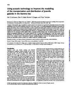
The driving force plot of Figure 6 shows the plot of ideal driving forces against cold composite curve temperatures. It helps to describe how close the driving force temperature of the heat exchangers is to the ideal. Exchangers that align with or fit the plot are termed good exchangers, while those crossing the composite curves show a bad driving force violation on the plot. The driving force plot has the ability of identifying cross pinch exchangers and those not making good use of the driving force. Cross pinch exchangers are those crossing the cold stream pinch temperatures on the plot. Exchangers transferring heat from above to below the pinch have larger driving forces than those implied by the plot, while exchangers transferring heat in the opposite direction show smaller driving forces. It is used to optimise the surface area requirement of the heat exchangers. Ideal matches will exactly coincide with the driving force plot. Exchangers which exchange heat vertically in the network will have their temperature driving forces coinciding with plot. For a cross pinch exchanger transferring heat across the pinch, the stream matches cannot align vertically. A good practical network will have exchangers with driving forces approaching the driving force plot. Thus the driving force plot is a very good qualitative tool to evaluate the performance of individual heat exchangers [8, 22].
Int. J. Pure Appl. Sci. Technol., 12(1) (2012), 39-48.
47
Figure 6 Driving Force Plot showing Hot Temperature – Cold Temperature Relationship From the network performance it can be seen that the operational network design is far above target. This is because of gross pinch rule violation and misapplication of the driving force principle as shown from Table 5 and Figure 6; the cross heat exchanger table and driving force plot respectively. The cross load is quite high supporting the fact that the heat exchanger network was designed during the cheap energy era. It also shows that pinch technology was not applied during the design of the heat exchanger network. Thus a retrofit is needed. This will help to eliminate the cross loads and optimise energy utilisation during crude preheating.
4. Conclusion: This research has highlighted the importance of simulation modelling in improving the performance of Chemical Engineering processes. Analysis of the heat exchanger network of the crude distillation unit of a functional refinery was used to buttress this fact. From the network performance it can be seen that the operational network design is far above target. The cross load is quite high supporting the fact that the heat exchanger network was designed during the cheap energy era. It also shows that pinch technology was not applied during the design of the heat exchanger network. Thus a retrofit is needed. This will help to eliminate the cross loads and optimise energy utilisation during crude preheating.
References [1] [2] [3]
[4] [5]
A.M. Law, Simulation Modeling & Analysis (4th Ed.), McGraw-Hill, London, 2007. P.J. Sanchez, Fundamentals of simulation modeling, Engineering Management Review, IEEE, 37(2009), 23-23. M. Morar and P.S. Agachi, Review: Important contributions in development and improvement of the heat integration techniques, Computers & Chemical Engineering, 34(2010), 1171-1179. K.C. Furman and N.V. Sahinidis, A critical review and annotated bibliography for heat exchanger network synthesis in the 20th century, Ind. Eng. Chem. Res., 41(2002), 2335-2370. T. Gundersen and L. Naess, The synthesis of cost optimal heat exchanger networks, Computers and Chemical Engineering, 12(6) (1988), 503-530.
Int. J. Pure Appl. Sci. Technol., 12(1) (2012), 39-48.
[6]
[7]
[8] [9]
[10] [11] [12] [13]
[14] [15] [16] [17] [18] [19]
[20] [21] [22] [23]
[24]
48
J. Jezowski, Heat exchanger network grassroot and retrofit design, the review of the state-ofthe-art: Part 1 heat exchanger targeting and insight based methods of synthesis, Hungarian Journal of Industrial Chemical, 22(1994a), 279-294. J. Jezowski, Heat exchanger network grassroot and retrofit design, the review of the state-ofthe-art: Part 2 heat exchanger network synthesis by mathematical methods and approaches for retrofit design, Hungarian Journal of Industrial Chemical, 22(1994b), 295-308. B. Linhoff and E. Hindmarch, The pinch design method for heat exchanger networks, Chemical Engineering Science, 38(5) (1983), 745-763. S. Ahmad, B. Linhoff and R. Smith, Cost optimum heat exchanger networks–2, targets and design for detailed capital cost models, Computers and Chemical Engineering, 14(7) (1990), 729-750. B. Linhoff, Pinch analysis – A state-of-the-art overview, Chem. Eng. Res. Des, 71(A) (1993), 503-522. K.K. Trivedi, B.K. O'Neill and J.R. Roach, Synthesis of heat exchanger networks featuring multiple pinch points, Computers & Chemical Engineering, 13(3) (1989), 291-294. R.M. Wood, K. Suaysompol, B.K. O’Neill, J.R. Roach and K.K. Trivedi, A new option for heat exchanger network design, Chemical Engineering Progress, 87(9) (1991), 38-43. X.X. Zhu, B.K. O’Neill, J.R. Roach and R.M. Wood, A method for automated heat exchanger synthesis using block decomposition and non-linear optimization, Chem. Eng. Res. Des, 73(A) (1995), 919-930. X.X. Zhu, Automated design method for heat exchanger network using block decomposition and heuristic rules, Computers and Chemical Engineering, 21(10) (1997), 1095-1104. S.A. Papoulias and I.E. Grossmann, A structural optimisation approach in process synthesis– 11 heat recovery networks, Computers and Chemical Engineering, 7(6) (1983), 707-721. C.A. Floudas, A.R. Ciric and I.E. Grossmann, Automatic synthesis of optimum heat exchanger network configurations, AICHE Journal, 32(1986), 276-290. C.A. Floudas and A.R. Ciric, Strategies for overcoming uncertainties in heat exchanger network synthesis, Computers and Chemical Engineering, 13(10) (1989), 1133-1152. X. Yuan, L. Pibouleau and S. Domenech, Experiments in process synthesis via mixed integer programming, Chemical Engineering Process, 25(2), (1989), 99-116. T.F. Yee and I.E Grossmann, Simultaneous optimisation models heat integration – II: Heat exchanger network synthesis, Computers and Chemical Engineering, 14(10), (1990), 11651184. K.R. AJao and H.F. Akande, Energy integration of crude distillation unit using pinch analysis, The Researcher, 1(2) (2009), 54-66. Nigeria Port Harcourt Refinery Company Limited Brochure, Nigeria National Petroleum Corporation (NNPC), Bureau of Public Enterprises, 1-15(2005). Linhoff March, Introduction to Pinch Technology, 1998, http://www.ou.edu/class/chedesign/a-design/Introduction%20to%20Pinch%20Technology-LinhoffMarch.pdf. B.K. Piagbo, Using simulation modelling to improve the performance of chemical engineering processes: retrofitting of the Port Harcourt refinery heat exchanger network (HEN) as case study, MSc. Thesis, Teesside University, Middlesbrough England, 2011. T.N. Tjoe, Retrofit of heat exchanger networks, Ph.D. Thesis, UMIST, England, 1986.