Using Software Architecture Techniques to Support the Modular Certification of Safety-Critical Systems Tim Kelly Department of Computer Science University of York Heslington, York, YO10 5DD United Kingdom
[email protected]
Abstract In software engineering the role of software architecture as a means of managing complexity and achieving emergent qualities such as modifiability is increasingly well understood. In this paper we demonstrate how many principles from the field of software architecture can be brought across to the field of safety case management in order to help manage complex safety cases. Traditional approaches to certification of modular systems as a statically defined configuration of components can result in a large certification overhead being associated with any module update or addition. A more promising approach is to attempt to establish a modular, compositional, approach to constructing safety cases that has a correspondence with the modular structure of the underlying architecture. This paper establishes the mechanisms for managing and representing safety cases as a composition of safety case ‘modules’. Having defined the concept of a modular safety case, the paper also describes principles for their definition and evaluation. An example generic modular safety case architecture for Integrated Modular Avionics (IMA) based systems is presented as a means of illustrating the concepts defined. Keywords: safety case, modularity, justification, composition, architecture
1
approach is to establish the safety case for a specific configuration of the architecture. However, this nullifies the benefit of flexibility in using a modular solution and will necessitate the development of completely new safety cases for future modifications or additions to the architecture. A more promising approach is to attempt to establish a modular, compositional, approach to constructing safety cases that has a correspondence with the modular structure of the underlying architecture. As with software architecture it would need to be possible to establish interfaces between the modular elements of the safety justification such that safety case elements may be safely composed, removed and replaced. Similarly, as with software architecture, it will be necessary to establish the safety argument infrastructure required in order to support such modular reasoning (e.g. an infrastructure argument regarding partitioning being required in order to enable independent reasoning concerning the safety of two system elements). By adopting a modular, compositional, approach to safety case construction it may be possible to: •
Justifiably limit the extent of safety case modification and revalidation required following anticipated system changes
•
Support (and justify) extensions modifications to a ‘baseline’ safety case
•
Establish a family of safety case variants to justify the safety of a system in different configurations
certification,
Introduction
Whilst the move towards modular systems and software architecture offers potential benefits of improved flexibility in function allocation, reduced development costs and improved maintainability, it can pose significant problems in certification. The traditional approach to certification relies heavily upon a system being statically defined as a complete entity and the corresponding (bespoke) system safety case being constructed. However, a principal motivation behind modular systems construction is that there is through-life (and potentially run-time) flexibility in the system configuration. For example, an Integrated Modular Avionics (IMA) system can typically support many possible mappings of the avionics functionality required to the underlying computing platform. In constructing a safety case for modular systems an attempt could be made to enumerate and justify all possible configurations within the architecture. However, this approach is unfeasibly expensive for all but a small number of processing units and functions. Another
2
and
Current Safety Case Development Practice
Safety case reports are often complex documents presenting complex arguments. Very rarely is it that safety cases are prepared by individuals. The reality is that the activity of establishing a safety case will be divided amongst a number of individuals, teams and, in some cases, organisations. To manage the complexity of safety case construction, system safety cases are often decomposed into subsystem safety cases. Many examples of this can be observed in current safety-critical systems: System safety cases incorporate software safety cases (a division advocated by Issue 2 of the U.K. Defence Standards 00-55 (MoD 1997) and 00-56 (MoD 1996)). A safety case concerned with the avionics of a complex military aircraft will be split into
separate safety cases for separate systems (such as the navigation system, engine control and flight control). The implied safety case for UK rail operations is made up of separate safety cases for station operations, infrastructure and rolling stock. However, it is well understood that safety is a system property. Extreme care must therefore be taken to ensure that safety case boundaries are drawn correctly, that arguments don’t “fall between the gaps”, and that formalising boundaries (e.g. through contractual agreements between organisations) doesn’t prevent the development of efficient safety solutions. Emergent safety properties, not dealt with by a “Divide and Conquer” approach to safety case construction, must also be addressed. Although the above examples already exist in practice, the overall structure ‘in-the-large’ of these safety cases and the interdependencies that exist between them are often poorly managed. In the following sections, we show it is possible to map across principles already established in the field of software architecture to help address this problem.
3
Safety Case Architecture
Software architecture has been defined in the following terms (Bass et al. 1998): “The structure or structures of the system, which comprise software components, the externally visible properties of those components, and the relationships among them” Safety case architecture can be defined in very similar terms: The high level organisation of the safety case into components of arguments and evidence, the externally visible properties of these components, and the interdependencies that exist between them Being clear of the externally visible properties of any safety case module allows us to appreciate its role within the overall safety case structure. The following can be regarded as the key ‘interface’ properties for any safety case module: 1.
Objectives addressed by the module
2.
Evidence presented within the module
3.
Context defined within the module
It is important to note that the definition of safety case architecture must give equal importance to the dependencies between safety case modules (or ‘components’) as to the components themselves. This thinking must be at the heart of any attempt to decompose the safety case. Safety is not a “sum of parts” property. Dependencies must therefore also be recorded as part of any interface definition, perhaps along the following lines: 4.
Arguments requiring support from other modules
5.
Reliance on objectives addressed elsewhere
6.
Reliance on evidence presented elsewhere
7.
Reliance on context defined elsewhere
Safety case modules can be usefully composed if their objectives and arguments complement each other – i.e. one or more of the objectives supported by a module match one or more of the arguments requiring support in the other. For example, the software safety argument is usefully composed with the system safety argument if the software argument supports one or more of objectives set by the system argument. At the same time, an important side-condition is that the collective evidence and assumed context of one module is consistent with that presented in the other. For example, the operational usage context assumed within the software safety argument must be consistent with that put forward within the system level argument.
4
Representing Modular Safety Cases in GSN
The Goal Structuring Notation (GSN) (Kelly 1997) - a graphical argumentation notation - explicitly represents the individual elements of any safety argument (requirements, claims, evidence and context) and (perhaps more significantly) the relationships that exist between these elements (i.e. how individual requirements are supported by specific claims, how claims are supported by evidence and the assumed context that is defined for the argument). The principal symbols of the notation are shown in Figure 1 (with example instances of each concept). The principal purpose of a goal structure is to show how goals (claims about the system) are successively broken down into sub-goals until a point is reached where claims can be supported by direct reference to available evidence (solutions). As part of this decomposition, using the GSN it is also possible to make clear the argument strategies adopted (e.g. adopting a quantitative or qualitative approach), the rationale for the approach (assumptions, justifications) and the context in which goals are stated (e.g. the system scope or the assumed operational role). For further details on GSN see (Kelly 1997). System can tolerate single component failures
Fault Tree for Hazard H1
Goal
Solution
Argument by elimination of all hazards
Strategy
All Identified System Hazards
Sub-systems are independent
A/J Assumption / Justification
Context
ParentGoal ChildGoal
Undeveloped Goal (to be developed)
Developed Goal
Child Goal
Uninstantiated Context
Choice
Figure 1: Principal Elements of the Goal Structuring Notation GSN has been widely adopted by safety-critical industries for the presentation of safety arguments within safety cases. However, to date GSN has largely been used for arguments that can be defined ‘stand-alone’ as a single artefact rather than as a series of modularised interconnected arguments. In order to make the GSN support the concepts of modular safety case construction it has been necessary to make a number of extensions to the core notation.
The first extension to GSN is an explicit representation of modules themselves. This is required, for example, in order to be able to represent a module as providing the solution for a goal. For this purpose, the package notation from the Unified Modelling Language (UML) standard has been adopted. The new GSN symbol for a safety case module is shown in Figure 2 (Right Hand Side). As has already discussed, in presenting a modularised argument it is necessary to be able to refer to goals (claims) defined within other modules. Figure 2 (left hand side) introduces a new element to the GSN for this purpose – the “Away Goal”. An away goal is a goal that is not defined (and supported) within the module where it is presented but is instead defined (and supported) in another module. The Module Identifier (shown at the bottom of the away goal next to the module symbol) should show the unique reference to the module where the goal can be found.
order to gain an appreciation of how modules interrelate “in-the-large” (e.g. as described in the “Module View” of Software Architecture proposed by Hofmeister et al. in (Hofmeister et al., 1999)) it can also be useful to express a module view between safety case modules. SysAccSafe {System X} is acceptably safe
ArgOverFunctions
SRFunctions Safety Related functions of {System X}
Argument over all identified safety related functions of {System X}
FunctionsInd All functions are independent IndependenceArg
FnASafe Function A operation is acceptably safe
FnBSafe Function B operation is acceptably safe
FnCSafe Function C operation is acceptably safe
FnBArgument
FnAArgument Safety Argument for Function A
Figure 2: GSN Elements Introduced to Handle Modularity Away goals can be used to provide support for the argument within a module, e.g. supporting a goal or supporting an argument strategy. Away goals can also be used to provide contextual backing for goals, strategies and solutions. Representation of away goals and modules within a safety argument is illustrated within Figure 3. The annotation of the top goal within this figure “SysAccSafe” with a module icon in the top right corner of the goal box denotes that this is a ‘public’ goal that would be visible as part of the published interface for the entire argument shown in Figure 3 as one of the “objectives addressed”. The strategy presented within Figure 3 to address the top goal “SysAccSafe” is to argue the safety of each individual safety-related function in turn, as shown in the decomposed goals “FnASafe”, “FnBSafe” and “FnCSafe”. Underlying the viability of this strategy is the assumed claim that all the system functions are independent. However, this argument is not expanded within this “module” of argument. Instead, the strategy makes reference to this claim being addressed within another module called “IndependenceArg” – as shown at the bottom of the away goal symbol. The claim “FnASafe” is similarly not expanded within this module of argument. Instead, the structure shows the goal being supported by another argument module called “FnAArgument”. The “FnBSafe” claim is similarly shown to be supported by means of an Away Goal reference to the “FnBArgument” module. The final claim, “FnCSafe”, remains undeveloped (and therefore requiring support) – as denoted by the diamond attached to the bottom of the goal. In the same way that in can it be useful to represent the aggregated dependencies between software modules in
Figure 3: Representing Safety Case Modules and Module References in GSN In the same way that in can it be useful to represent the aggregated dependencies between software modules in order to gain an appreciation of how modules interrelate ‘in-the-large’ (e.g. as described in the ‘Module View’ of Software Architecture proposed by Hofmeister et al. in (Hofmeister et al. 1999) it can also be useful to express a module view between safety case modules. If the argument presented within Figure 3 was packaged as the “TopLevelArg” Module, Figure 4 represents the module view that can be used to summarise the dependencies that exist between modules. Because the “FnAArgument” and “FnBArgument” modules are used to support claims within the “TopLevelArg” module a supporting role is communicated. Because the “IndependenceArg” module supports a claim assumed as context to the arguments presented in “TopLevelArg” a contextual link between these modules is shown.
FnAArgument Function A Safety Argument
TopLevelArg
IndependenceArg
Top Level System X Safety Argument
Functional Independence Argument
FnBArgument Function B Safety Argument
Figure 4 – Example Safety Argument Module View In a safety case module view, such as that illustrated in Figure 4, it is important to recognise that the presence of a SolvedBy relationship between modules A & B implies that there exists at least goal within module A that is supported by an argument within module B. Similarly, the existence of an InContextOf relationship between modules
A & B implies that there exists at least one contextual reference within module A to an element of the argument within module B. Alongside the extensions to the graphical notation of GSN, the following items of supporting documentation are required: Interface declaration for each safety case module – along the lines outlined in section 3, the external visible properties of any safety case module must be recorded – e.g. the goals it supports, the evidence (solutions) it presents, the cross-references (‘Away Goal’ references) made to / dependencies upon other modules of argument. Figure 5 depicts the items to be defined on the boundary of a safety case module expressed using the GSN.
Step 2 – Consistency Checks If matched goals are found as a result of Step 1, assess whether the context and solutions defined by Module B (i.e. those listed under items 2 and 3 of the declared interface for Module B) are consistent with the context and solutions defined by Module A (i.e. those listed under items 2 and 3 of the declared interface for Module A). Step 3 – Handling Cross-References a,
Where cross-references are made by Module A to Module B (i.e. Away Goal, Context and Solution references listed under items 5-7 of the declared interface for Module A) check that the entities referenced do indeed exist within Module B.
b,
Conversely, Where cross-references are made by Module B to Module A (i.e. Away Goal, Context and Solution references listed under items 5-7 of the declared interface for Module B) check that the entities referenced do indeed exist within Module A.
Goals Supported
'Away' Goal 'Away' Context
Safety Case Module
Context Defined
Evidence Presented
Goal to be Supported
Context Defined
'Away' 'Away' Solution Goal
Figure 5 – The Published Interface of a GSN Safety Case Module Contracts for composed modules – where co-dependent safety case modules are used together within a system safety case a contract must be recorded of the dependencies resolved between the separate arguments. This is discussed further in section 6.
5
Module Composition with GSN Modules
The following three steps must be undertaken when attempting to usefully compose two safety case modules A & B with interfaces as defined in the previous section: Step 1 – Goal Matching a,
b,
Assess whether any of the goals requiring support in Module A (i.e. those listed under item 4 of the declared interface for Module A) match the goals addressed by Module B (i.e. those listed under item 1 of the interface for Module B). Conversely, assess whether any of the goals requiring support in Module B (i.e. those listed under item 4 of the declared interface for Module B) match the goals addressed by Module A (i.e. those listed under item 1 of the interface for Module A).
It may seem strange to include both steps 1a and 1b – i.e. admitting the possibility that whilst Module B supports Module A, Module A may also support Module B. However, circularity of ‘SupportedBy’ relationships between modules does not automatically imply circularity of argument (cross-references may be to separate legs of the argument within a module). The defined context of one module may also conflict with the evidence presented in another. For example, implicit within a piece of evidence within one module may be the simplifying assumption of independence between two system elements. This assumption may be contradicted by the model of the system (clearly identifying dependency between these two system elements) defined as context in another module. There may also simply be a problem of consistency between the system models (defined in GSN as context) defined within multiple modules. For example, assuming a conventional system safety argument / software safety argument decomposition – as defined in Issue 2 of the U.K. Defence Standards 00-56 (MoD 1996) and 00-55 (MoD 1997) – the consistency between the state machine model of the software (which, in addition to modelling the internal state changes of the software will almost inevitably model the external – system – triggers to state changes) and the system level view of the external stimuli. As with checking the consistency of safety analyses, the problem of checking the consistency of multiple, diversely represented, models is also a significant challenge in its own right.
6
Safety Case Module ‘Contracts’
Where a successful match (composition) can be made of two or more modules, a contract should be recorded of the agreed relationship between the modules. This contract aids in assessing whether the relationship continues to hold and the (combined) argument continues to be sustained if at a later stage one of the argument modules is modified or a replacement module substituted. This is a commonplace approach in component based software engineering where contracts are drawn up of the services a software
component requires of, and provides to, its peer components, e.g. as in Meyer’s Smalltalk contracts (Meyer 1992) and contracts in object-oriented reuse (Helm 1990). In software component contracts, if a component continues to fulfil its side of the contract with its peer components (regardless of internal component implementation detail or change) the overall system functionality is expected to be maintained. Similarly, contracts between safety case modules allow the overall argument to be sustained whilst the internal details of module arguments (including use of evidence) are changed or entirely substituted for alternative arguments provided that the guarantees of the module contract continue to be upheld. A contract between safety case modules must record the participants of the contract and an account of the match achieved between the goals addressed by and required by each module. In addition the contract must record the collective context and evidence agreed as consistent between the participant modules. Finally, away goal context and solution references that have been resolved amongst the participants of the contract should be declared.
7
Principles of Safety Case Architecture Definition
In this paper safety case architecture is defined as the high level organisation of the safety case into modules of argument and the interdependencies that exist between them. In deciding upon the partitioning of the safety case, many of the same principles apply as for software architecture definition, for example: •
High Cohesion / Low Coupling – each safety case module should address a logically cohesive set of objectives and (to improve maintainability) should minimise the amount of cross-referencing to, and dependency on, other modules.
•
Supporting Work Division & Contractual Boundaries – module boundaries should be defined to correspond with the division of labour and organisational / contractual boundaries such that interfaces and responsibilities are clearly identified and documented.
•
Supporting Future Expansion – module boundaries should be drawn and interfaces described in order to define explicit ‘connect’ points for future additions to the overall safety case argument (e.g. additional safety arguments for added functionality).
•
Isolating Change – arguments that are expected to change (e.g. when making anticipated additions to system functionality) should ideally be located in modules separate from those modules where change to the argument is less likely (e.g. safety arguments concerning operating system integrity).
The principal aim in attempting to adopt a modular safety case architecture for modular systems architecture is for the modular structure of the safety case to correspond as far as is possible with the modular partitioning of the
hardware and software of the actual system. Arguments of functional (application) safety would ideally be contained in modules separate from those for the underlying infrastructure (e.g. for specific processing nodes of the architecture). Additionally, cross-references from application arguments to claims regarding the underlying infrastructure need to be expressed in non-vendor (non-solution) specific terms as far as is possible. For example, part of the argument with the safety case module for an application may depend upon the provision of a specific property (e.g. memory partitioning) by the underlying infrastructure. It is desirable that the cross-reference is made to the claim of the property being achieved rather than how the property has been achieved. In line with the principles of module interfaces and contracts as defined in the previous two sections, this allows alternative solutions to achieving this property to be substituted without undermining the application level argument. From this example, it is possible to see that in addition to thoughtful division of the safety case into modules, care must be taken as to the nature of the cross-references made between modules.
8
Patterns in Safety Case Architecture?
Well-understood architectural patterns in software architecture (such as the use of indirection and abstraction layers) can be seen to have immediate analogues in safety case architecture. Figure 6 illustrates this point with a simple three-tier ‘layered’ safety case architecture. The top tier (the Top System Level Argument module) sets out objectives in a form (e.g. Defence Standard 00-55 (MoD 1997) System Integrity Level requirements) that cannot immediately be satisfied by the objectives supported (e.g. Civil Aerospace Guidance DO178B (RTCA 1992) Development Assurance Level claims) in the bottom tier (the Software Safety Argument module). To solve this problem, an indirection layer (the DAL to SIL Mapping Argument module) is inserted between the top and bottom tiers. This module makes the read-across argument from the DAL regime to the SIL regime. (If sufficiently well defined, such a read-across argument may be usefully reused in future safety cases). Figure 7 illustrates the possible internal structure of the read-across argument contained within the middle tier of the safety case architecture shown in Figure 6. The published goal of the read-across argument is the claim expressed in the form required by the target application context (i.e. in this case in terms of a Defence Standard 00-55 SIL Claim). This claim is then decomposed into the specific claims regarding the key process and product requirements required (according to 00-55) in order to satisfy the SIL requirement (e.g. testing claims, claims regarding coding standards, language choice etc.). At the bottom of the argument shown in Figure 7 is an (undeveloped) goal regarding compliance to a Development Assurance Level that is known to be supportable from the available evidence (i.e. from the bottom tier of the architecture shown in Figure 6). Working bottom-up, the read-across argument then infers that in order to support this DAL claim the individual requirements dictated by DO178B for this DAL must also have been satisfied. The argument therefore draws out
(above the DAL claim) these individual implicated sub-claims. The challenge in creating the read-across argument now lies in relating the specific claims required in order to support the SIL claim to the specific claims required in order to support the DAL claim. This approach attempts to read-across from one claim to another by deconstructing each claim in to its constituent parts and then relating these parts. It should be noted that the interrelation of SIL and DAL subclaims depicted in Figure 7 (where claims of one type are shown to be directly supportable by claims of the other) is a simplification. In reality, more complex chains of argument should be expected between the claims of each type.
SystemArgument
9
Managing Changes to a Modular Safety Case
Maintainability is one of the principle objectives in attempting to partition a safety case into separate modules. When change occurs that impacts traditional safety cases (defined as total entities for a specific configuration of system elements) reassessment of the ‘whole’ case is often necessary in order to have confidence in a continuing argument of safety. In such situations it will often be the case that for certain forms of change large parts of the safety required no reassessment. However, without having formally partitioned these parts of the case behind well-defined interfaces and guarantees defined by contracts it is difficult to justify non re-examination of their arguments. When changes occur that impact a modular safety case it is desirable that these changes can be isolated (as far as is possible) to a specific set of modules whilst leaving others undisturbed. The definition of interfaces and the agreement of contracts mean that the impact path of change can be halted at these boundaries (providing interfaces are sustained and contracts continue to be upheld).
Top Level System Argument Needs support for: {DefStan 00-55 SIL Claim}
DALToSILMappingArgument Read across argument from DO178B DAL claims to DS 00-55 SIL claims Provides support for: {DefStan 00-55 SIL Claim} Needs support for: {DO178B DAL Claim}
SoftwareArgument Software Safety Argument Provides support for: {DO178B DAL Claim}
In extremis for a modular system it is desirable that when entire modules of the system are replaced, applications removed or added, or when the hardware of part of the system is substituted for that of a different vendor correspondingly entire modules of the safety case can be removed and replaced for those that continue to sustain the same safety properties. However, in order to achieve this flexibility, the following considerations need to be made for both the definition of context and the nature of cross-references made between modules: •
Avoid unnecessary restriction of context – It was highlighted in section 5 that the significant ‘side-condition’ of composing two or more modules together is that their collective context must be consistent. Often, the more specialised or restricted context is defined the harder it becomes to satisfy this condition (through incompatibility between defined contexts being more likely). For example, one module of the safety case may assume for the purposes of its argument that the temperature operating range is 10-20°C (i.e. the safety argument holds assuming the operating temperature is no less than 10°C and not greater than 20°C) whilst another modules may assume that the operating temperature is 20-30°C. Both ranges would form part of the defined context for each module and would create an inconsistency upon composition of the modules.
•
There will be specific occasions when it is necessary to restrict the assumed context of an module in order for the module argument argument to hold. However, narrowing of context should be avoided as far as is possible. An analogy can be made with the operating range of a conventional mains power adaptor. If the adaptor is qualified over the entire operating range 110-250 volts then it may be used in wider number of situations (e.g. for both 110-120V main supply and 230-240V mains supply). If the adaptor is qualified to
Figure 6 – Safety Case Architecture employing an abstraction layer
{DefStan 00-55 SIL Claim}
{SIL Requirement Satisfaction Claim}
{SIL Requirement Satisfaction Claim}
{SIL Requirement Satisfaction Claim}
{SIL Requirement Satisfaction Claim}
{DAL Requirement Satisfaction Claim}
{DAL Requirement Satisfaction Claim}
{DAL Requirement Satisfaction Claim}
{DAL Requirement Satisfaction Claim}
{DO178B DAL Claim}
Figure 7 – Illustration of argument structure of DAL to SIL ‘Abstraction’ Layer Module
a narrower operating range then obviously its scope of applicability is more restricted. •
•
Goals to be supported within modules should state limits rather than objectives – Borrowing terminology from the ALARP (As Low as Reasonably Practicable) framework (HSE 2001), ‘limits’ refer to the boundary between tolerable and intolerable risks, whilst ‘objectives’ refer to the boundary between tolerable and negligible risks. In order to permit the widest range of possible solutions of combinations with other modules, unsupported goals within a module (i.e. goals that will have to be supported through composition of this module with another) should define acceptability criteria rather than ‘desirability criteria’. (More informally, this means stating “what you will accept” vs. “what you want”). It is easier to for another module to exceed (i.e. improve upon) a limit than it is to fail to meet an objective that was too harshly defined. Wherever possible boundary goals should ideally communicate both of limit and objective aspects of any requirement (by means of defining clearly the acceptance context of any undeveloped goal). Goals to be supported within modules and ‘Away’ Goals should refer to ‘ends’ rather than ‘means’ – This issue has already been briefly discussed in section 7. In a similar vein to the previous observation, if goals on the boundary of modules or cross-references to goals between modules refer to claims regarding outcomes (e.g. a claim of memory partitioning) rather than means of achieving these outcomes (e.g. the specific mechanisms that ensure memory partitioning) then this leaves flexibility as to how solutions (supporting arguments) are provided – i.e. many possible alternative argument modules may be composed with this reference rather than just one specific form of argument.
A true assessment of the modifiability of any proposed safety case architecture can only be achieved through consideration of realistic change scenarios and examination of their impact on the module structure of the architecture. This form of evaluation is discussed further in the following section.
10 Safety Case Architecture Evaluation In the discipline of software architecture early lifecycle assessment of any proposed architecture is encouraged to gain an appreciation of how well the architecture supports required architectural quality attributes such as scalability, performance, extensibility and modifiability. To assess software architectures (particularly with regard to modifiability) a scenario based evaluation technique – SAAM (Software Architecture Analysis Method) (Kazman et al. 1996) – has been developed by Kazman et al. The activities performed in a SAAM assessment are discussed briefly below: 1.
Develop Scenarios – Definition of scenarios that illustrate activities and changes that the architecture should ideally accommodate.
2.
Describe candidate architecture – Definition of the candidate architecture or architectures in a suitably expressive architectural description language (ADL) that can be easily understood by all parties involved in the analysis.
3.
Classify Scenarios – Classification of scenarios into the two categories of direct and indirect scenarios. Direct scenarios are those scenarios that an architecture is expected to accommodate without change. Indirect scenarios describe situations where change to elements within the architecture is anticipated.
4.
Perform Scenario Evaluations – For each indirect scenario, identification of the changes to the architecture that are necessary for it to support the scenario, together with an estimation of the effort required to make these changes. For each direct scenario, a walkthrough should be conducted that shows clearly how the scenario is accommodated by the architecture.
5.
Reveal Scenario Interactions – Identification of where two or more indirect scenarios involve change to the same element of the architecture. The interaction of semantically unrelated scenarios can indicate a lack of cohesion in how architectural elements are defined.
6.
Overall Evaluation – Based upon the results of all the scenarios analysed, evaluation of whether the proposed architecture adequate supports the required quality attributes.
With little modification, this method of architecture evaluation can be read-across to the domain of safety case architecture. One of the overriding aims in defining a modular safety case architecture is improve maintainability and (as a subtype of maintainability) extensibility. However, it is difficult to determine a priori whether a proposed safety case architecture (such as that presented in section 11) will be maintainable. Adopting a similar approach to SAAM but for safety case architectures would suggest that a number of change ‘scenarios’ should be identified. These scenarios should attempt to anticipate all credible changes that could impact the safety case over its lifetime (e.g. a change of hardware manufacturer, addition of functionality). For each of these change scenarios (NB – by definition these scenarios would be classified as indirect in the SAAM methodology), a walkthrough should be conducted to assess the likely impact of the change upon the individual modules of the proposed safety case architecture. In the SAAM method, the effects of indirect scenarios are classified according to the following three classes of change: •
Local Change – change isolated within a single module of the architecture.
•
Non-Local Change – change forced to a number of modules within the architecture.
•
Architectural Change – widespread change forced to a large proportion of modules within the architecture.
Scenario #2
Application A is rewritten and interacts with Application B differently from before.
These ideas can also be usefully applied to the safety case architecture domain. Ideally, for a modular safety partitioned and carefully cross referenced in accordance with the principles stated in this paper the effects of all credible scenarios would fall within the first of the categories listed above. To illustrate how the categories of change read-across to the concept of a modular safety case architecture consider a simple safety case architecture as shown in Figure 8 containing the following four modules:
Scenario #3
Change is made to the system memory management model that enables new means of possible (unintentional) interaction between applications.
SysArg
Safety case module containing the top level safety arguments for the overall system identifying top level claims for each application run as part of the system and a top level claim regarding the safety of the interactions between applications.
AppAArg
Safety case module containing the arguments of safety for Application A.
AppBArg
Safety case module containing the arguments of safety for Application B.
InteractionArg
Safety case module containing the arguments of safety for the interactions between Applications A and B.
The ‘SysArg’ module is supported by the ‘AppAArg’, ‘AppBArg’ and ‘InteractionArg’ modules. The ‘AppAArg’ module relies upon guarantees of safe interaction with Application B as defined by the claims contained within the ‘InteractionArg’ module (hence ‘AppAArg’ is shown making a contextual reference to ‘InteractionArg’). Similarly, the safety argument for Application B (‘AppBArg’) relies upon guarantees of safe interaction with Application A as defined in the ‘InteractionArg’ module.
The effect of scenario #1 would be that the safety argument for Application A (‘AppAArg’) would need revision to reflect the new implementation. However, provided that the safety obligations of the module to the other modules (as defined by the contracts between the module safety case interfaces) continue to be upheld no further change to other modules would be necessary. Figure 9 depicts the effects of this scenario (a cross over a module indicates that the module is ‘challenged’ by the change and revision is necessary). The effects of this scenario could be regarded as a local change. The effect of scenario #2 would be that not only must the safety argument for Application A (‘AppAArg’) be revised but in addition the safety argument for the interaction between modules (contained in ‘InteractionArg’) would need to be rexamined in light of the altered interaction between applications A and B. If, however, the revised ‘InteractionArg’ could continue to support the same assurances to the Application B argument of the safety of interactions with Application A then the Application B safety arguments (contained in ‘AppBArg’) would be unaffected. Figure 10 depicts the effects of this scenario. The effects of this scenario could be regarded as a non-local change (owing to the fact that the change impact has spread across a number of modules). SysArg
SysArg
AppBArg AppAArg
InteractionArg
AppBArg AppAArg
InteractionArg
Figure 9 – Illustration of Local Change SysArg
Figure 8 – A Simple Safety Case Architecture The following are three possible change scenarios that could have an impact on the outlined safety case architecture Scenario #1
Application A is rewritten (perhaps including some additional functionality) but still preserves the safety obligations as defined in the contract between AppAArg, SysArg and InteractionArg.
AppBArg AppAArg
InteractionArg
Figure 10 – Illustration of Non-Local Change
established once-for-all leading to support from SpecificHardwareArg modules for particular hardware choices.
SysArg
ResourcingArg: Overall argument concerning the sufficiency of access to, and integrity of, resources (including time, memory, and communications) AppBArg AppAArg
InteractionArg
Figure 11 – Illustration of Architectural Change The effect of scenario #3 is that it changes the nature of possible interactions between all applications. As such, the safety argument for the interaction between modules (contained in ‘InteractionArg’) would obviously need to be revised. It is likely that the nature of the assurances given by interaction argument to the safety arguments for applications A and B (as defined by the contracts between ‘InteractionArg’ and ‘AppAArg’, and between ‘InteractionArg’ and ‘AppBArg’) could be altered. Consequently both of these modules could be impacted. The change to the memory management model may even such that it alters the nature of the top level claim that needs to be made in the ‘SysArg’ module regarding the safety of application interactions (i.e. the ‘SysArg’ module may also be affected. Figure 11 depicts the effects of this scenario. The effects of this scenario could be regarded as architectural (owing to the fact that the change can potentially impact many modules). This is perhaps to be expected as this scenario describes modifying a fundamental services provided as part of the system infrastructure.
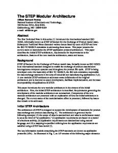
11 Example Modular Safety Case Architecture for IMA The principles of modularising and evaluating safety case architecture have been applied in reworking a “Generic Avionics Safety Argument” developed by Pygott (Pygott 1999). The resultant safety case architecture is shown in Figure 13. (Note – for clarity not all of the dependencies between modules have been shown on this diagram). The role of each of the modules of the safety case architecture shown in Figure 13 is as follows: ApplnAArg: Specific argument for the safety of Application A (one required for each application within the configuration) CompilationArg: Argument of the correctness of the compilation process. Ideally established once-for-all. HardwareArg: Argument for the correct execution of software on target hardware. Ideally abstract argument
ApplnInteractionArg: Argument addressing the interactions between applications, split into two legs: one concerning intentional interactions, the second concerning non-intentional interactions (leading to the NonInterfArg Module) InteractionIntArg: Argument addressing the integrity of mechanism used for intentional interaction between applications. Supporting module for ApplnInteractionArg. Ideally defined once-for-all. NonInterfArg: Argument addressing non-intentional interactions (e.g. corruption of shared memory) between applications. Supporting module for ApplnteractionArg. Ideally defined once-for-all PlatFaultMgtArg: Argument concerning the platform fault management strategy (e.g. addressing the general mechanisms of detecting value and timing faults, locking out faulty resources). Ideally established once-for-all. (NB Platform fault management can be augmented by additional management at the application level). ModeChangeArg: Argument concerning the ability of the platform to dynamically reconfigure applications (e.g. move application from one processing unit to another) either due to a mode change or as requested as part of the platform fault management strategy. This argument will address state preservation and recovery. SpecificConfigArg: Module arguing the safety of the specific configuration of applications running on the platform. Module supported by once-for-all argument concerning the safety of configuration rules and specific modules addressing application safety. TopLevelArg: The top level (once-for-all) argument of the safety of the platform (in any of its possible configurations) that defines the top level safety case architecture (use of other modules as defined above). ConfigurationRulesArg: Module arguing the safety of a defined set of rules governing the possible combinations and configurations of applications on the platform. Ideally defined once-for-all. TransientArg: Module arguing the safety of the platform during transient phases (e.g. start-up and shut-down). Ideally generic arguments should be defined once-for-all that can then be augmented with arguments specifically addressing transient behaviour of applications.
TopLevelArg Top Level System Argument for the platform + configured applications
SpecificConfigArg Safety argument for the specific configuration of the system
ApplnAArg
ApplnBArg
Specific safety arguments concerning the functionality of Application A
Specific safety arguments concerning the functionality of Application B
ConfigRulesArg ApplnInteractionArg Argument for the safety of interactions between applications
Safety argument based upon an allowable set of configurations
Hardware Arg
CompilationArg (As Example) Arguments of the integrity of the compilation path
NonInterfArg
InteractionIntArg
Arguments of the absence of non-intentional interference between applications
Arguments concerning the integrity of intentional mechanisms for application interaction
Arguments of the correct execution of software on target hardware
PlatformArg Arguments concerning the integrity of the general purpose platform
PlatFaultMgtArg Argument concerning the platform fault management strategy
ResourcingArg Arguments concerning the sufficiency of access to, and integrity of, resources
TransientArg Arguments of the safety of the platform during transient phases
Figure 13 – Safety Case Architecture of Modularised IMA Safety Argument An important distinction is drawn between those arguments that ideally can be established as ‘once-for-all’ arguments that hold regardless of the specific applications placed on the architecture (and should therefore be unaffected by application change) and those that are configuration dependent. Examples of application configuration specific modules include the ‘ApplnAArg’, ‘ApplnBArg’ and ‘ApplnInteractionsArg’ modules. Examples of the argument models established ‘once for all’ include the ‘NonInterfArg’ and ‘InteractionIntArg’ modules. Table 1 summarises the modules falling under each category. Argument Modules Established ‘Once-for-all’ ApplnAArg CompilationArg HardwareArg ResourcingArg InteractionIntArg NonInterfArg PlatFaultMgtArg ModeChangeArg TopLevelArg ConfigurationRulesArg TransientArg
Configuration Dependent Argument Modules ApplnAArg ApplnInteractionArg SpecificConfigArg
Table 1 – Categorisation of Safety Case Architecture Modules
In the same way as there is an infrastructure and backbone to the IMA system itself the safety case modules that are established once for all possible application configurations form the infrastructure of this particular safety case architecture. These modules (e.g. NonInterfArg) establish core safety claims such as non-interference between applications by appeal to properties of the underlying system infrastructures. These properties can then be relied upon by the application level arguments.
12 Minimising the Impact of Change The intention of the partitioning of the safety case, such as in the approach described in the example above, is to maximise the number of arguments (modules) that are stable in the presence of change. As explained in section 10 in order to evaluate the success of the argument in this respect it is necessary to identify a number of credible change scenarios for the IMA-based system. Credible scenarios could include: •
Hardware Vendor Change
•
Addition of a single application
•
Removal of a single application
•
Modification of existing application
•
Addition of extra processing nodes
•
Remove of processing nodes
•
Change of Databus
Some of these scenarios may be accommodated easily by the proposed safety case architecture. For example, if the applications in a configuration change, although individual application arguments (e.g. “ApplnAArg” module) and application interaction arguments (i.e. those within the “ApplnInteractionArg” module) must be updated, argument of interaction integrity and non-interference (the “InteractionIntArg” and “NonInterfArg” modules) may well be able to stay unaltered. Other scenarios, such as change of hardware vendor may have a wider impact across the modules of the safety case (e.g. impacting compilation arguments as well as the more obvious hardware arguments). For the architecture proposed, Table 2 provides illustrative examples of the modules affected by credible change scenarios. Change Scenario
Impact on Safety Case Modules
Application A modified
ApplnAArg must be updated All other (13) modules unaffected provided that interface of ApplnAArg is preserved ApplnCArg must be established SpecificConfigArg must be updated ApplnInteractionArg must be updated All other (12) modules unaffected provided that interface of ApplnInteractionArg is preserved HardwareArg and other arguments that specifically address the hardware of the system (such as InteractionIntArg) must be updated. All other modules unaffected provided that the interface of the updated modules can be preserved (i.e. the same ‘guarantees’ can be made for the properties of the new hardware as for the old).
Application C added
Introduction of new hardware type
Table 2 - Example Change Scenario Impact Summaries It is through the ability to leave many of the modules of the safety case undisturbed in the presence of change (as illustrated in Table 2) that the benefits of IMA can be carried through to the certification process.
13 Reasoning about Independence
Partitioning
and
One of the main impediments to reasoning separately about individual applications running on an IMA based architecture separately is the degree to which applications interact or interfere with one another. DO178B (RTCA 1992), in discussing partitioning between software elements developed to differing Development Assurance Levels identifies that there are a number of possible routes through which interference is possible:
•
Hardware Resources – processors, memory, Input Output devices, timers etc.
•
Control Coupling – vulnerability to external access
•
Data Coupling – shared data, including processor stacks and registers.
•
Hardware Failure Modes
For example, partitioning must be provided to ensure that one process cannot overwrite the memory space of another process. Similarly, a process should not be unintentionally allowed to overrun its allotted schedule such that it deprives another process of processor time. The European railway safety standard EN 50129 (CENELEC 2001) makes an interesting distinction between those interactions between system components that are intentional (e.g. component X is meant to communicate with component Y) are those that are unintentional (e.g. the impact of electromagnetic interference generated by one component on another). Unintentional interactions are typically the result of an error (whether random or systematic). For example, the unintentional interaction of one process overwriting the memory space of another is a fault condition. A further observation made in EN 50129 is that there are a class of interactions that are non-intentional but created through intentional connections. An example of this form of interaction is the influence of a failed processing node that is ‘babbling’ and interfering with another node through the intentional connection of a shared databus. The safety case architecture promotes (in the “NonInterfArg” module) the ideal that ‘once-for-all’ arguments are established by appeal to the properties of the IMA infrastructure to address unintentional interactions. For example, a “non interference through shared memory space” argument could be established by appeal to the segregation offered by a Memory Management Unit (MMU). An argument of “non-interference through shared scheduler” could be established by appeal to the priority-based scheduling scheme offered by the scheduler. Although the particular forms of interference between applications will need to be drawn out (within the “ApplnInteractionArg” module) it is expected that these specific arguments can be addressed through the general infrastructure arguments provided by the “NonInterfArg” module. It is not possible to provide “once-for-all” arguments for the intentional interactions between components – as these can only be determined for a given configuration of components. However, it is desirable to separate those arguments addressing the logical intent of the interaction from those addressing the integrity of the medium of interaction. For example, if application A passes a data value to application B across a data bus it would be desirable to partition those arguments that address the possibility of A sending to wrong value to B from the arguments that address the possible corruption of the data value on the data bus. Both issues must be clearly identified and reasoned about (within the
“ApplnInteractionArg” module). However, the supporting arguments concerning the integrity of the medium of interaction can be established “once-for-all” within the “InteractionIntArg” module.
14 Implications for Certification Processes A modular approach to safety case construction has implications for the acceptance process. Whereas, traditionally certification has involved accepting, at a single point in time, a single monolithic safety case for an entire system for the benefits of a modular safety case approach to be realised requires a certification process that acknowledges the structure of a partitioned safety case that can be extended and modified without instantly requiring re-evaluation of the entire case. The guidance document ARINC 651 (ARINC 1991) recognises this fact for suggests that for IMA-based systems the certification tasks are comprised of the following three distinct efforts: •
Confirmation of the general environment provided by the cabinet
•
Confirmation of the operational behaviour of each function (application) intended to reside within a cabinet
•
Confirmation of the resultant composite of the functions
ARINC 651 also recognises that conventional safety standards (such as DO178B (RTCA 1992)) may need to be updated to reflect these new distinct tasks. These observations can be clearly related to the example IMA safety case architecture presented within this paper. Confirmation of the “general environment” involves qualification of both the hardware and software infrastructure (e.g. operating system) and relates to those modules shown within the proposed architecture that should ideally be established once for all possible application configurations (e.g. the ‘HardwareArg’ module). Confirmation of the operational behaviour of each function relates to the specific application argument modules (e.g. the ‘ApplnAArg’ module) shown within the proposed architecture. Confirmation of the composite operation of functions relates to those arguments, specific to a configuration of applications, that address the interaction of applications (e.g. the ‘ApplnInteractionArg’ and ‘SpecificConfigArg’ modules). ARINC 651 talks explicitly of the need for “building block qualification” whereby it is possible to “separately quality certain building blocks of an IMA architecture in order to reduce the certification effort required for any particular IMA-hosted function”. Example building blocks listed include specific arguments relating to the (ARINC 629) global data bus, the ARINC 659 backplane bus, the robust partitioning environment and the cabinet hardware / software environment. Again, it is easy to see a correspondance with the IMA safety case architecture proposed within this paper (e.g. the ‘NonInterfArg’ module addressing robust partitioning and the ‘InteractionIntArg’ module addressing the integrity of bus communication). However, no detail regarding how these
building block arguments are to be represented and managed is presented within ARINC 651. In order to design and validate the various building blocks involved in IMA, ARINC 651 identifies the need for “rules which govern how the building blocks work together”. It additionally describes that, “a feature of these rules of application is that they can be used to limit the work associated with certifying and re-certifying an IMA function to proof of compliance with the rules, and qualification of the function itself. Regulatory agency discussion is encouraged to establish how certification credit may be granted for adherence to these rules”. This concept of defining rules between building blocks relates strongly to the principles of establishing well-defined module interfaces and contracts between safety case modules put forward within this paper. As the quote above clearly highlights, a necessary part of a new certification process based upon modular safety cases is to clearly give credit (i.e. limit the required re-certification) where contracts between safety case modules are upheld in the light of change to, or reconfiguration of, modules within the overall safety case.
15 Summary In order to reap the potential benefits of modular construction of safety critical and safety related systems (e.g. ease of later addition or replacement of functionality, or through-life flexibility of hardware vendors) a modular approach to safety case construction and acceptance is also required. This paper has explained some of the key concepts and principles of a modular safety case approach, including safety case module interface definition, cross-referencing between safety case modules and the steps involved in composition of one or more safety case modules. Specifically, the paper has described how the Goal Structuring Notation (GSN) may be extended to include and support these concepts. Use of these extensions has been illustrated by means of an example modular safety case architecture for IMA-based systems. This paper has attempted to illustrate how concepts established in the field of software architecture – such as design-by-contract, scenario-based evaluation and architectural patterns – can be seen to have obvious analogues in the safety case architecture domain.
16 Acknowledgements The author would like to acknowledge the financial support given by QinetiQ for the work reported in this paper.
17 References Kelly, T. P. (1997) A Six-Step Method for the Development of Goal Structures, York Software Engineering. Jones, C. (1983) Specification and design (parallel) programs, Proc. IFIP Information Processing 83, 1983. Hofmeister, C., Nord, R., Soni, D. (1999) Applied Software Architecture, Addison-Wesley
MoD (1996) Defence Standard 00-56 Safety Management Requirements for Defence Systems, U.K. Ministry of Defence MoD (1997) Defence Standard 00-55 Requirements of Safety Related Software in Defence Equipment, U.K. Ministry of Defence Meyer, B. (1992) Applying Design by Contract, Computer, 25:40-52, IEEE Press Helm, R., Holland, I. M., Gangopadhyay, D. (1990) Contracts: Specifying Behavioural Compositions in Object-Oriented Systems, Proceedings of the ACM Conference on Object-Oriented Programming Systems, Languages and Applications (OOPSLA), 169-180, October 1990 RTCA (1992), DO-178B: Software Considerations in Airborne Systems and Equipment Certification, RTCA, Washington D.C., December 1 1992. HSE (2001), Reducing Risk, Protecting People – HSE’s Decision Making Process, HSE Books Kazman, R., Abowd, G., Bass, L., Clements, P. (1996) Scenario-based analysis of software architecture, Software, 13:47-55, IEEE Press CENELEC (2001), EN 50159:2001; Railway Applications - Communication, signalling and processing systems Safety-related communication in closed transmission systems, CENELEC ARINC (1991) Design Guidance for Integrated Modular Avionics, Aeronautical Radio, Inc., Annapolis, Maryland Report 651, November 9 Pygott, C. (1999) Certification Analysis Techniques for an IMA Architecture, Internal DERA report DERA/CIS/CIS3/CR990865, December 1999