Using Static Parametric Design to Support Systems Engineering of Industrial Automation Systems
Hongchao Ji1 Lars Mikelsons1 Karl Kempf1 Dieter Schramm2 1 Bosch Rexroth AG, Lohr am Main, Germany {hongchao.ji, lars.mikelsons, karl.kempf}@boschrexroth.de 2 University of Duisburg-Essen, Duisburg, Germany
[email protected]
Abstract
This paper proposes a static parametric design methodology for application of the model based systems engineering (MBSE) paradigm in the world of Modelica. This methodology allows for parameter synthesis of the industrial automation systems under consideration of customer requirements. Furthermore, the parametrized system can be verified automatically. An integrated system model consisting of requirements, system design and verification models is created and can be used as a design template to generate a new parameter set according to the change of customer requirements. A case study from the practice is presented to proof the concept of this methodology. Keywords: Model Based Systems Engineering, SysML, Modelica, Parameter Synthesis
1 Introduction The complexity of modern industrial automation systems increases steadily. New functions and technologies need to be integrated to fulfill customer requirements, environmental regulations and/or safety standards. The increasing complexity has raised many challenges such as keeping the the design consistent and approving the correctness with respect to the customer requirements. Model based systems engineering (MBSE) is defined as the formalized application of modeling to support system requirements, design, analysis, verification and validation activities beginning in the conceptual design phase and continuing throughout development and later life cycle phases. Hence MBSE is a suitable approach to cope with these challenges. One of the key issue in MBSE process is to determine the proper dimension of the system design acDOI 10.3384/ecp12076971
cording to the formalized requirements model. The static parametric design methodology uses Modelica static models together with the dynamic models to support the MBSE process by the means of selecting the proper components of the desired system from given product catalogs, dimensioning the sub-systems as well as checking the correctness of the system design with respect to systems requirements. The objective of the static parametric design methodology is to perform a parameter synthesis of a technical system according to the customer requirements automatically. Furthermore, the calculated system design can be verified automatically as well. The Systems Modelling Language (SysML) [11] is used to formalize the customer requirements. Moreover, the extension of abstraction levels and classification defined in [4] is also applied in this paper. Work on the integration of SysML and Modelica has already proven its effectiveness in the MBSE [6, 8, 9]. Reusing these improvements the SysML models can be transformed into executable Modelica models. In this contribution, we focus on the standard application that the structure of the desired system is normally known to the system engineers. The requirements models serve as the basis of the static parametric design methodology. By changing the requirements models, a new parameter set of the system can be obtained automatically. In this sense, the integrated model consisting of requirements, system design and verification models can be seen as a design template for a standard application. This paper is organized in 6 sections. Section 2 illustrates the current systems engineering process and the need of model based systems engineering and static parametric design methodology. As part of related work in Section 3 a short introduction to SysML and its integration with Modelica are given. Section 4 introduces the static parametric design methodology
Proceedings of the 9th International Modelica Conference September 3-5, 2012, Munich, Germany
971
Using Static Parametric Design to Support Systems Engineering of Industrial Automation …
to support the systems engineering in detail. The capaare demonstrated bilities of the proposed methodology using an industrial application in Section 5. The paper closes with conclusions and an outlook to future work.
to the contractual situation. The definition of levels of abstraction is an appropriate way to meet these needs. The depicted levels of abstraction in Figure 2 reflect the described supplier chain and major technologies involved and therefore are a reasonable choice in the context of automation systems. In order to deal with 2 Systems Engineering of Industrial the complexity of large systems the design objects are Automation Systems clustered in a system break down structure. The requirements derived on the different levels of abstracThe systems engineering process is described in the tion can be referenced in requirement specifications in following referring to the well known V Model ac- order to provide the contractual views on subsets of cording to the VDI 2206 standard [12] depicted in requirements. (Figure 1). Requirement
n Desig
Syste m In
m Syste
Assurance of Properties
tegra ti
on
Product
Domain-specific Design Mechanical Engineering Electrical Engineering Information Technology
Figure 2: Levels of Abstraction in Requirements and System Design
Modelling and Model Analysis
Figure 1: V Model According to VDI 2206 [12]
2.2
Systems Design
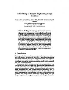
The main tasks of current systems engineering of industrial automation systems can be summarized as Industrial automation systems are characterized by follows: their ability to process a material or work piece according to a defined procedure to achieve the output of • State the customer needs correctly and unama desired product. The challenge of the system engibiguously; neer is to design a machine that is capable to run the • Define the proper system design based on the cus- process in a deterministic and efficient way. This task is typically performed within a specific design domain tomer requirements; that refers to a field of technical expertise. The proper • Verify the system design against customer re- selection of the components and their integration into quirements. the overall structure strongly influence the function, performance, robustness and reliability of the whole They will be introduced respectively in the following. system. Currently the selection of the components is mainly determined by the competence of the system 2.1 Requirements Specification engineers which is time consuming and error prone. Due to the fact that the requirement specification is In order to avoid manual errors, it is desired to select the subject matter of contract between customer and the components in a systematical manner. Today, parameter synthesis of a technical system is contractor the above described context implies that the requirements engineering has to be seen not only from usually based on static calculations in the field of inthe technical perspective but also needs to consider the dustrial automation systems. A small example of such business process and the contractual situation along static calculation for selection of a hydraulic valve in the supplier chain. In this context it is self-evident that a hydraulic lift system is depicted in Figure 3. The dithe requirements shall be defined and structured not mension of the cylinder shall be first defined in order only according to technical aspects but also according to calculate the maximal flow rate through the valve 972
Proceedings of the 9th International Modelica Conference September 3-5, 2012, Munich Germany
DOI 10.3384/ecp12076971
Hongchao Ji, Lars Mikelsons, Karl Kempf and Dieter Schramm
2.4
with the given maximal cylinder velocity by Qmax = AD · vmax .
(1)
After that the nominal size of the valve is determined by some design criteria. Moreover, the design criteria origin from customer requirements as well. In this case, the nominal size is defined by the nominal flow rate which is calculated by Qnominal = 1.5 · Qmax .
(2)
The nominal size of the valve can be chosen from the product catalog according to the nominal flow rate. That means a proper component, in this case the valve, is correctly selected for the desired system.
The Challenges
Since industrial automation systems usually consist of components from different domains, it is hard to keep the design correct and consistent. In order to deal with this fact, the systems design from different engineering domains shall be integrated into the whole MBSE process. Therefore, a universal and standardized modeling language is required which shares the understanding among engineers from different disciplines. This common language shall enable the generation of requirements models, system design models, traceability models as well as verification models containing domain-specific details. SysML is being proposed to meet this requirement. However it has been evaluated as not sufficient due to the lack of executable semantics. Integration of the languages SysML and Modelica has proven its efficiency in the area of MBSE [5, 6, 7, 10]. Therefore, in this contribution SysML and Modelica are chosen as the modelling languages applied in our MBSE process as well. In order to set up a MBSE tool for parameter synthesis, the following two questions have to answered: 1. How to perform a parameter synthesis to determine all the proper components based on the customer requirements in an automatic manner? 2. How to link different kinds of models in the whole MBSE process?
Figure 3: Schematic of a Hydraulic Lift System
These two challenges have been addressed in this paper by the means of using static parametric design methodology in an integrated system model based on SysML and Modelica. The details are presented in Section 4.
In order to ensure the acceptance of a MBSE tool offering the methodology presented in this paper, these 3 design guidelines have to be integrated into the MBSE 3.1 tool.
2.3
Verification and Validation
Model based verification and validation of a systems design against systems requirements has been widely used in the field of industrial automation systems. The goal here is to verify the system design in an automated and reproducible way. Since this issue has already been addressed in virtual verification of systems design against systems requirements (vVDR) methodology [10], it is used to approve the systems design in this paper as well. DOI 10.3384/ecp12076971
Background and Related Work The SysML and Modelica
SysML is a general purpose language used in the field of systems engineering. It is defined as a UML profile which reuses subsets of UML constructs and extends them with some additional modeling elements. SysML is capable to capture the textual requirements and to allocate them with the design models and test cases. However due to loosely defined executable semantics SysML is not capable to execute the modeled physical systems. In contrast to that, Modelica is an object oriented and equation based modeling language for multi-domain physical systems. Graphical modeling is supported by the object diagram which offers an
Proceedings of the 9th International Modelica Conference September 3-5, 2012, Munich, Germany
973
Using Static Parametric Design to Support Systems Engineering of Industrial Automation …
intuitive way to describe power transmission through acausal connections as well as directed signal flows. Strong semantics allow the generation of executable models of continuous as well as discrete systems. Object oriented language constructs enable the efficient reuse of models and the design of comprehensive and easy to use model libraries. As mentioned in Section 2, a language which integrates the descriptive modeling power of SysML and the formal executable simulation power of Modelica seems to be a promising approach for the systems engineering in industrial automation systems.
3.2
Related Work
Several work has already been done towards application of MBSE paradigm using Modelica language with different concerns. The vVDR methodology [10] addresses mainly the virtual verification of systems requirements by using UML, Modelica and ModelicaML. In Dubois et. al. [2] a requirement traceability model to enforce the traceability concept in SysML in the automotive domain is presented. Requirements management and allocation have already been covered in the other paper of the author [4]. This paper describes a methodology for the parameter synthesis of technical systems according to customer requirements. Moreover, the different kinds of models are linked with the other models in the integrated system model and therefore it is easy to regenerate and to verify the final parametrized system. They will be introduced in detail in the following section.
4 Static Parametric Design The proposed static parametric design methodology is based on Modelica static models. Static models are defined as models that are constant over time. Considering the whole MBSE process, the following items can be formalized as Modelica static models: • Requirement Specifications, • Product Catalogs, • Selection Criteria.
4.1
Definitions of Models
This classification is mainly based on the taxonomy proposed in [3] with some changes as presented in the following. Instead of the requirement type specific quality, the structural requirement is defined in the field of industrial automation. • A functional requirement is the requirement that should produce an expected reaction to a given stimuli. • A performance is the requirement to check whether a system variable such as timing, speed, volume or throughput is in a desired range. • A structural requirement is the requirement which describes the structural demand of the stakeholder. • A constraint is the requirement to provide the technical and safety boundary conditions that the system shall satisfy. The product catalogs models are easy to understand as Modelica static models. They can modeled as a simple record class with some table definitions. In this work, a UML library with a sub-set of the Bosch Rexroth catalog is implemented and later transformed to Modelica static models. The advantages of implementation as UML library over Modelica library is the compatibility with SysML and the extendibility of the product catalog. The selection criteria are implemented as static calculation models. The idea is using Modelica functions to determine the proper dimension of the components. Normally, those selection criteria for the components are usually the same. Due to the fact of reuseability, a Modelica library called ParametricDesign which consists of most selection criteria in the field of industrial automation systems is built as shown in Figure 4. Besides the static models, simulation model is an executable model which is used for dynamic simulation. In the verification and validation phase, the simulation model is linked with the test cases to check the correctness of the parametrized system design. All those models are further transformed into Modelica static models with the help of a Modelica code generator, which is implemented with the help of Eclipse Acceleo [1].
The requirement specifications can be defined as re4.2 Link of Different Models quirements models which are captured as stereotyped SysML models according to the different abstraction Several models have been defined in this static paralevels and classifications in [4]. metric design methodology. It is necessary to link 974
Proceedings of the 9th International Modelica Conference September 3-5, 2012, Munich Germany
DOI 10.3384/ecp12076971
Hongchao Ji, Lars Mikelsons, Karl Kempf and Dieter Schramm
4.3
Methodology Description
The prerequests of application of the static design methodology are • hydraulic library, • static design library, • product catalog library.
Figure 4: Structure of the Parametric Design Library
those models in a efficient manner in order to perform a parameter synthesis automatically. The basic idea is to reference the attributes of SysML model to the variables, parameters and constants of the Modelica model. Currently, these relations have been established manually which is time consuming and error prone. A method to extend the standard relationships such as «satisfy», «verify» and «derive» has been proposed in [4]. An overview of the linking of different models in this methodology is shown in Figure 5. The tooling that supports the binding of related objects is implemented in Eclipse.
Furthermore, the formalized requirements models and at least one simulation model have to be created at first as the basis for application of the static parametric design methodology. The main steps of this methodology can be summarized as follows: 1. Capture the customer requirements as stereotyped requirements according to the proposed classification in [4]. 2. Create a simulation model from the hydraulic library on the considered level of abstraction. 3. Select the proper design criteria from the parametric design library and create the static calculation model. 4. Link the requirements model, static calculation model as well as product catalog model in the parametric design model. 5. Run a parameter synthesis to obtain a best suited parameter set and the other possible parameter sets for the desired system. 6. Set the obtained possible parameter sets in the simulation model and save them as design variants. 7. Define test cases that need to satisfy customer requirements. 8. Link the requirements model, test cases as well as simulation models in the verification model. 9. Run a verification that executes all related test cases and design variants.
Figure 5: Link of Different Models 10. Choose the best suited design variants according to the verification results. DOI 10.3384/ecp12076971
Proceedings of the 9th International Modelica Conference September 3-5, 2012, Munich, Germany
975
Using Static Parametric Design to Support Systems Engineering of Industrial Automation …
5 Application Example In this section, a hydraulic lift system is used to demonstrate the static parametric design methodology. The hydraulic lift system is used to lift a load to a given height. It shall be considered in the context of the OEM-supplier relation as it applies to a typical Bosch Rexroth engineering project. The task of this case study is to define a best suited parameter set of the desired lift system which fulfills all the customers requirements as well as technical constraints. First of all, a simulation model shall be created. Therefore, the structure of the hydraulic lift system has to be known for the system engineers. Then, the static calculation model shall be created as well by selecting the proper design criteria from the parametric design library. After linking of different models in the integrated system model, a parameter synthesis can be performed to obtain the best combination of the components with the minimal dimension which satisfy all the requirements. The main advantage is that the system engineers can use the integrated system model as a design template. With the help of this design template, it is much more easier to variate the parameter set of the hydraulic lift system by changing the customer requirements automatically.
5.1
Requirements Capture
The requirements from the customers are formalized as follows: a load of 3000 kg shall be lifted to 0.5 m within 2 s. Besides the customer requirement there are some technical constraints of the desired system. For example, the maximum velocity can not exceed 0.6 m/s. The other important constraint is that the pressure drop over the proportional valve shall not exceed 30% of the working pressure. The important requirements are listed in Table 1. The beginning letter of the ID of the requirement refers to the type of the requirement. The requirements P1, C2 and C3 can be verified by test cases which are modeled as Modelica models. Since the structral requirments S4 and S5 provide only the important design parameters, they are not necessary or possible to verify. According to those requirements, the proper components from the product catalogs shall be selected iteratively until all the components are chosen. They can be formalized as SysML requirements model and later transformed into Modelica static model. An example of the requirements model and its generated Modelica code are shown in Figure 6. 976
ID P1 C2 C3 S4 S5
Description The load shall be lifted to 0.5 m within 2 s. The max. velocity shall not exceed 0.6 m/s. The pressure loss over the valve shall not exceed 30% of the working pressure. The mass of the load is 3000 kg. The working pressure is 200 bar. Table 1: The System Requirements List
Figure 6: An Example of Requirements Model and Generated Modelica Code
5.2
Modelling of the Hydraulic Lift System
The object diagram (Figure 7) shows the structure of the hydraulic lift system. The load is lifted by a differential cylinder which is driven by a constant pressure source. The proportional valve is controlled by a simple P-controller to realize the position control. Since the focus of this work is to illustrate the static parametric design methodology, the details about the model will not be introduced here.
5.3
Static Parametric Design Process
The involved components from the product catalog are the differential cylinder and proportional valve. Hence, the design criteria models for those two components in the design library are selected into the static parametric design model together with the requirements model. Table 2 and 3 show the important design variables from the product catalogs of differential cylinder and proportional valve.
Proceedings of the 9th International Modelica Conference September 3-5, 2012, Munich Germany
DOI 10.3384/ecp12076971
Hongchao Ji, Lars Mikelsons, Karl Kempf and Dieter Schramm
cording to those design variables the corresponding components with the proper size are chosen until all the components from the product catalog are chosen. The following table shows the automatic generated best suite combination of cylinder and valve, which is defined as an optimal design. It is worth to mention
Cylinder Optimal Valve Figure 7: Object Diagram of the Hydraulic Lift System Piston Diameter mm 40 50 63 80 100 125 140
Rod Diameter mm 28 36 45 56 70 90 100
Max Stroke mm 2000 2000 2000 2000 3000 3000 3000
Optimal
Piston Diameter mm 100 Nominal Size – 25
Rod Diameter mm 70 Max Flow Rate l/min 900
Max Stroke mm 3000 Pressure Drop bar 350
Table 4: Selected Components from Product Catalog that the gain of the P-controller is determined by "Try and Error". In the future, this kind of parameter which is not related to the product catalog can be defined by the means of optimization.
5.4
Verification of System Design
After the static parametric design process is done, a best suited set of combination of the components is Table 2: Product Catalog of Differential Cylinders obtained. An automatic verification will check the optimal design against customer requirements. This Nominal Max Pressure is done by using vVDR methodology [10] to model Size Flow Rate Drop the test case of requirements with violation monitor. l/min bar – According to the requirements definitions in Table 1, 10 170 80 three test cases are defined to verify the requirements 16 450 180 P1, C2 and C3. Figure 8 shows the verification result 25 900 350 of this proposed optimal design. The first two figures 27 1000 430 (Figure 8(a) and 8(b)) illustrate that the load is lifted to 35 3500 1100 0.5 meter after 2 second and does not exceed the maximal velocity. As shown in Fiugre 8(c), the pressure Table 3: Product Catalog of Proportional Valves loss over the valve in steady state satisfies the critical 30% of working pressure 200 bar as well. Therefore, The requirements variables defined in the require- the hydraulic lift system with the automatic selected ments models, such as mass of load, maximum veloc- parameter fulfills the customer requirement and techity and desired lifting position are taken as inputs for nical constraints. the design criteria which are implemented as Modelica functions. Finally, a parametric design model is ob- 5.5 Comparison of Design Variants tained by linking the requirements models, static calculation models and the related product catalog mod- The best suited combination of components from the els. product catalog are supposed to have the minimal size After the parametric design model is created, the which satisfy all the requirements. It has been verified automatic parameter synthesis can be done very con- to fulfill all the requirements in the last section. Nevveniently. The parametric design model is interactive ertheless, it is still not proved that the performance of solved and the design variables are calculated. Ac- this design is better than the others variants. In order DOI 10.3384/ecp12076971
Proceedings of the 9th International Modelica Conference September 3-5, 2012, Munich, Germany
977
Using Static Parametric Design to Support Systems Engineering of Industrial Automation …
s [m]
Load Position
Comparison Load Position
0.5
0.4 0.2
0.4 0
0
0.5
1
1.5
2
2.5
Desired Optimal Variant 1 Variant 2 Variant 3 Variant 4
3
s [m]
t [s]
(a) Load Position
0.3
0.2
Load Velocity 1
v [m/s]
0.1 0.5 0
0
0
0.5
1
1.5
2
2.5
3
t [s] −0.5
0
0.5
1
1.5
2
2.5
3
t [s]
(a) Comparison of Load Position
(b) Load Velocity Comparison Load Velocity
Pressure Loss
1.4
200
p [bar]
150
Maximal Optimal Variant 1 Variant 2 Variant 3 Variant 4
1.2
100
1
50 0
0.5
1
1.5
2
2.5
3
t [s]
(c) Pressure Loss
Figure 8: Verification Results of Optimal Design
s [m]
0.8 0
0.6 0.4 0.2 0 −0.2
0 0.5 1 1.5 2 2.5 3 to validate this, design variants around the optimal det [s] sign with other nominal sizes can be generated from (b) Comparison of Load Velocity this methodology. The design variants are defined by substituting the components of the optimal design with Figure 9: Comparison of Cylinder Positions and Vea smaller or larger nominal size. In this case, four de- locities of Different Design Variants sign variants are automatically generated and used to compare with the optimal design. The dimension of all the design variants are shown in the following table. the test cases are shown in Table 6. Furthermore, the Design Piston Rod Valve costs of design variants depending on the dimensions Variants Diameter Diameter Size of selected components from the product catalog can also be calculated. With the help of this verification Optimal 100 70 25 matrix and the price, the selected optimal combination Variant 1 80 56 25 of the components from the product catalog is proved Variant 2 100 70 16 to be exact the best suited design. Variant 3 100 70 27 Variant 4 125 90 25
Table 5: Dimensions and Costs of Design Variants The simulation results of the optimal design and the other four design variants are shown in Figure 9. It shows that the design variant 1 and 3 can approach the desired position within 2 seconds. However the velocities exceed the maximal velocity constraint 0.6 m/s. The design variant 2 and 4 fulfill the second test case and can not satisfy the first one. The results concerning the third test case are listed in Table 6. A verification matrix of the design variants against 978
Design Variants Optimal Variant 1 Variant 2 Variant 3 Variant 4
Test Case 1 passed passed failed passed failed
Test Case 2 passed failed passed failed passed
Test Case 3 passed passed passed failed failed
System Cost 2000 1700 1820 2040 2400
Table 6: Verification Matrix and System Costs
Proceedings of the 9th International Modelica Conference September 3-5, 2012, Munich Germany
DOI 10.3384/ecp12076971
Hongchao Ji, Lars Mikelsons, Karl Kempf and Dieter Schramm
5.6
Acknowledgments
Open Issues
This case study demonstrates the proposed static pa- This work is funded by Bosch Rexroth AG and Gerrameter design methodology. According to the cus- man Federal Ministry of Education and Research tomer requirements and technical constraints, the di- (BMBF) in the ITEA2 OPENPROD project. mension of the desired system can be defined automatically. However, the main drawback is that the simulation model shall be first modeled. That means References this methodology can not be applied to arbitrary sys[1] http://www.acceleo.org. tem. This is due to the fact that there is not enough information for determining a proper combination of [2] Hubert Dubois, Marie-Agnès Peraldi-Frati, and the desired system in the practice. This drawback also Fadoi Lakhal. A Model for Requirements Tracelimit the application of MBSE in the field of industrial ability in a Heterogeneous Model-Based Design automation systems. Process: Application to Automotive Embedded It is noticed that the order for the selection of comSystems. In 15th IEEE International Conference ponents is fixed in this case, i.e., the dimension of on Engineering of Complex Computer Systems, cylinder shall be first defined in order to determine the ICECCS 2010, Oxford, United Kingdom, 22-26 nominal size of the proportional valve. Sometimes the March 2010, pages 233–242, 2010. order is not fixed. For both cases the system engineers shall have the chance to determine the order for the [3] Martin Glinz. On Non-Functional Requirements. In 15th IEEE International Requirements Engiselection of components more freely without reimpleneering Conference, RE 2007, October 15-19th, mentation of static design model. Since Modelica is a 2007, New Delhi, India, pages 21–26, 2007. standardize equation-based modelling language, it has been chosen to meet these requirements. It is capable to deal with the this issue. One proposed concept is [4] Hongchao Ji, Oliver Lenord, and Dieter Schramm. A Model Driven Approach for to switch the variability of parameter and variable of Requirements Engineering of Industrial Austatic models in an arbitrary manner. The system entomation Systems. In Proceedings of the gineers can give the known parameters until the static 4th International Workshop on Equationmodel is balanced and solvable to calculate the other Based Object-Oriented Languages and Tools unknown variables. (EOOLT’07), pages 13–24, 2011.
6 Conclusion and Future Work In this paper a static parametric design methodology has been analyzed in the systems engineering context of industrial automation systems. A set of possible design variants with different dimensions can be automatically generated and compared by using this methodology. The concept has been demonstrated by a case study of a typical engineering project. The other contribution of this work is allocation of this methodology in a MBSE process in which the parametrized design variants are fully traceable to the other models. In the future, the proposed methodology will be implemented as an Eclipse plug-in for better tool support of the static parametric design. It is usually the case, not all the parameters can be defined by the static parametric design methodology. Integration of an optimizer to define those parameters is desired. Application of a big scenario is also a part of future work. DOI 10.3384/ecp12076971
[5] Thomas Johnson, Christiaan J.J. Paredis, and Roger Burkhart. Integrating Models and Simulations of Continuous Dynamics into SysML. In Proceedings of 6th International Modelica Conference, Bielefeld, Germany, 3-4,March, 2008, 2008. [6] Christiaan J.J. Paredis, Yves Bernard, Roger M. Burkhart, Hans-Peter de Koning, Sanford Friedenthal, Peter Fritzson, Nicolas F. Rouquette, and Wladimir Schamai. An Overview of the SysML-Modelica Transformation Specification. In 2010 INCOSE International Symposium, July 2010. [7] Adrian Pop, David Akhvlediani, and Peter Fritzson. Towards Unified System Modeling with the ModelicaML UML Profile. In Proceedings of the 1st International Workshop on EquationBased Object-Oriented Languages and Tools (EOOLT’07), pages 13–24, 2007.
Proceedings of the 9th International Modelica Conference September 3-5, 2012, Munich, Germany
979
Using Static Parametric Design to Support Systems Engineering of Industrial Automation …
[8] Wladimir Schamai. Modelica Modeling Language (ModelicaML). Technical report, EADS Innovation Works, Germany, 2009. [9] Wladimir Schamai, Peter Fritzson, Chris Paredis, and Adrian Pop. Towards Unified System Modeling and Simulation with ModelicaML: Modeling of Executable Behavior Using Graphical Notations. In Proceedings of the 7th International Modelica Conference, Como, Italy, 20-22 September 2009, number 43 in Linköping Electronic Conference Proceedings, pages 612–621. Linköping University Electronic Press, Linköpings universitet, December 2009. [10] Wladimir Schamai, Philipp Helle, Peter Fritzson, and Christiaan J. J. Paredis. Virtual Verification of System Designs against System Requirements. In Models in Software Engineering - Workshops and Symposia at MODELS 2010, Oslo, Norway, October 2-8, 2010, Reports and Revised Selected Papers, pages 75–89, 2010. [11] http://www.omgsysml.org. [12] VDI. Design Methodology for Mechatronic Systems (VDI 2206). Technical report, VDI, 2004.
980
Proceedings of the 9th International Modelica Conference September 3-5, 2012, Munich Germany
DOI 10.3384/ecp12076971