Using Structures to Synchronize Cameras of Robots Swarms Richard Chang, Sio-Hoi Ieng and Ryad Benosman
Abstract— The synchronization of image sequences acquired by robots swarms is an essential task for localization operations. We address this problem by considering the swarms as dynamic camera networks in which, each robot is reduced to a mobile camera. The synchronicity is a strong restriction that in some cases of wide applications can be difficult to obtain. This paper studies the methodology of using a non synchronized camera network. We consider the cases where the frequency of acquisition of each element of the network can be different, including desynchronization due to delays of transmission inside the network. The following work introduces a new approach to retrieve the temporal synchronization from the multiple unsynchronized frames of a scene. The mathematical characterization of the 3D structure of scenes is used as a tool to estimate synchronization value, combined with a statistical stratum. This paper presents experimental results on real data for each step of synchronization retrieval.
I. INTRODUCTION Mobile robots using vision for navigation have to be synchronized if some cooperative works have to be performed. These tasks are mutual localizations, local mapping, etc... that can be done by realtime process or offline treatments. We are studying this problem from a computer vision point of view by considering the robots as mobile cameras, hence a set of several robots can be seen as a dynamic camera network that is subject to change and to be reconfigured through time. The synchronization operation is a task that complexifies many vision operations as the number of cameras becomes higher : cameras calibration, 3D reconstruction, frames synchronization, etc... Baker and Aloimonos [2], Han and Kanade [5] introduced pioneering approaches of calibration and 3D reconstruction from multiple views. The reader may refer to [9], [11], [4] for other interesting work on camera networks. Works on synchronization of cameras from images can be found in [16], [15], [10]. The aim is to retrieve synchronization in order to compute correctly 3D structures from a set of cameras. A solution is to set hardware synchronization as in [7]. But this kind of method can be not appliable because of spatial constraints. In these cases, a software-based synchronization can be a way to solve this problem. Most of the former works assume cases of desynchronization R. Chang, S. Ieng and R. Benosman are with Institut des Systemes Intelligents et de Robotique, Universit´ e Pierre and Marie Curie-Paris6, 4 Place Jussieu 75252 Paris, France
[email protected],sio-
[email protected],
[email protected]
with highly constraints hypotheses which exclude heavy delays problems. In [12], [13], a set of five moving points is tracked and matched throughout sequences for synchronization. Constraints can also be set on the scene or on the geometry of the cameras studying feature points [9] or trajectories [3] of the objects. Ushizaki et al. [14] show the limitations of these approaches and present a method based on co-occurrences of appearance changes in video sequences. This method uses appearance changes as temporal features but the cameras have to be stationary and it may fail when appearance changes, due to temporal shift, are not dominant. In this paper, we introduce a new synchronization technique. From all available frames which can be synchronized or not, 3D structures are reconstructed regardless they are correct or not. We will then show that correct ones occur only from synchronized frames. If we have a prior knowledge of the exact models of the observed objects, synchronization can be recovered by determining frames that lead to shapes complying with the models. However most of the time, this knowledge is not available. We introduce then an statistical approach which assumes that correct shapes reconstructions (given by synchronized frames) occur more frequently than distorted ones (given by non synchronized frames). A distribution model of the 3D reconstructions can be established where wrong shapes are marginal cases of the correct ones. We will also explain the method used to compute 3D shapes from available frames and the way we characterize them such that discrimination between correct and wrong reconstructions is possible. The main contributions of the paper are: •
•
A new method for retrieving correct 3D shapes of objects viewed by a unsynchronized camera network without any prior information on the observed objects. The synchronicity between different cameras can be found using computed 3D shapes of objects in the scene with no restrictions on the cameras’ framerate or time shift. Our only constraint is to assume non deformable objects.
This paper is organized as follows. Section two describes the theoretical basis of our method. In Section three, we will describe the synchronization algorithm. Finally, Section four and five deal with the synchronization of a camera network with experimental results.
planar motions.
II. Problem formalization A. Generalities Let CL and CR be two cameras of a stereoscopic system (for the rest of the paper, indexes L and R will refer to the corresponding camera). The acquisition time functions for both cameras are defined as xL and xR that map each image indexed by n and m respectively to their acquisition time. If TL and TR are the acquisition periods, then : xL (n) xR (m)
+
= TL ∗ n = TR ∗ m
TL ∈ R T R ∈ R+
(1) (2)
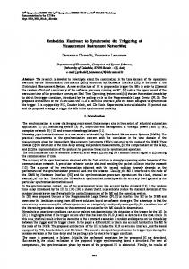
Let P1 ,P2 ,P3 and P4 be four collinear points viewed by CL and CR of centers OL and OR (see figure 2). Since the Pi are collinear, we have the following relations : D P1 P2 P3 P2
= k P1 P 4 k = KP1 P4 = M P 3 P4
where D, K and M are constant scalars. When the cameras CL and CR are synchronized, we have
OL
P4
The cameras are by default unsynchronized, let ∆(m, n) be the temporal shift between the mth and the nth frames of CL and CR : ∆(m, n) = xL (n) − xR (m) = TL · n − TR · m
4
t
P1
OR Fig. 2. If the images from the cameras CR and CL are synchronized, the points P1 , P2 , P3 and P4 can be correctly reconstructed from images.
a correct 3D reconstruction and the three equations (4)(6) are always satisfied whether the structure is moving or not. If the cameras are not synchronized, the rays will produce a new point set {P0i } which is different to the set {Pi } (see figure 3). Since we only assume non deformable (t+δ)
xR xL
F
OL
3
(t)
P' 4
2
δ td
P' 1
OR 4
P3
P' 2
∆t
1
P4
P' 3
∆ t=0
2
0 0
P3 P2
(3)
The synchronization is achieved when one is able to identify for each frame indexed by m of CR , the frame indexed by n of CL acquired at the same time (or equivalently the shift ∆(m, n)). In a general case, ∆(m, n) can be non constant for all m, we assume however that we have a coarse idea of ∆max , the maximum possible desynchronization between CL and CR . For each m, we set up an interval F = [xR (m) − ∆max ; xR (m) + ∆max ] such that the acquisition time of the nth image of CL is included in it. Figure 1 gives an illustration of a simple case of constant desynchronization.
(4) (5) (6)
K∈R M ∈R
6
8
10
n Fig. 1. xR and xL are represented in the particular case of TR = TL = 30frames/sec. ∆(m, n) is constant and equal to 66ms and the width of F is set to 6 indexes, thus for the 6th image of CR , F is the interval [4;8]. On can see that the 4th and the 6th frames of CL and CR respectively are acquired in the same time.
B. Reconstructing with unsynchronized frames. It is reasonable to assume that correct reconstructions are possible if frames are synchronized and that unsynchronized frames lead likely to distorted results. We will prove in this section that this assumption is mathematically true : ”correct reconstructions” are equivalent to ”synchronized frames” if observed objects are rigid bodies. This can be done by examining simple
P2 P1
Fig. 3. The cameras CR and CL are unsynchronized. The projection from image to space produces the shape P01 P02 P03 P04 at different positions according to the rigid body hypothesis.
body, if the collinearity is not preserved by the {P0i } then the reconstructions are obviously wrong, thus we are only considering cases for which the {P0i } are collinear. In such condition we can similarly establish three relations for theses points : D0 P01 P02 P03 P02
= k P01 P04 k = K 0 P01 P04 = M 0 P03 P04
0
K ∈R M0 ∈ R
(7) (8) (9)
The {P0i } are incorrectly reconstructed points if some trivial metric properties satisfied by the {Pi } are no more true. For example, if at least one of the equations (10) to
(12) is not satisfied, then the reconstruction is incorrect (P0i 6= Pi ). D K M
0
= D = K0 = M0
(10) (11) (12)
Let us show now that if these three equations are satisfied, then we have P0i = Pi . Then, there is only one correct reconstruction, which can be obtained when the frames are synchronized. If we look at the figure 3, we can see that the lines (P1 P4 ) and (P01 P04 ) intersect the same pencil of rays from OL . We can then apply the cross ratio : k P01 P02 k k P03 P02 k k P 1 P 2 k k P3 P 2 k / / = k P 1 P 4 k k P3 P 4 k k P01 P04 k k P03 P04 k
(13)
By combining the equations (4) to (9) with the equation (13), we get : K K0 = 0 (14) M M If K = K 0 , then M = M 0 hence : k P 3 P2 k k P03 P02 k = k P 3 P4 k k P03 P04 k
(15)
This equality is the Thal`es’ theorem, satisfied by {Pi } and {P0i } only if the lines (P1 P4 ) and (P01 P04 ) are parallel. If the equation (11) is satisfied, then there is only one reconstruction that also satisfies the equation (10). This solution corresponds to the case where P0i = Pi (the case where the points are behind the centre of camera is rejected). This proves that for non synchronized cameras, the exact reconstructions of simple rigid structures are not possible, thus we can expect better result for complex ones. C. Experimental measurements on basic structures A correct reconstruction is a reliable criterion to recover synchronization between cameras. If correct shapes are unknown, we have to extract it from images sequences. We postulate that among all reconstructions performed by combining the set of images, the correct one is the most recurrent one. We will show this assertion through two experiments. 3D reconstructions are tested on synthetic and real data of two unsynchronized cameras. 1) Synthetic data: We assume δ as the temporal shift between CL and CR . OL is chosen as the origin of the world coordinate frame and P1 P4 defined an object moving through the scene (see figure 3). Let us examine the figure 4. CL sees P1 at t (i.e. P1 (t)) and because of δ, CR sees the same point at t + δ (i.e. P1 (t + δ)). 0 The reconstruction P1 of P1 from the frames will be the intersection of (OL P1 (t)) and (OR P1 (t + δ)), hence : P01 (t) = α1 P1 (t) = OR +α10 (P1 (t+δ)−OR )
P'1 (t)
P1(t)
P1(t+ δ)
OL OR
Fig. 4. Due to the delay, the point P01 is constructed from points P1 (t) and P1 (t + δ) seen by CL and CR .
This equality is a set of three equations (one for each component) from which the scales factors can be expressed from the other parameters. For example, with the equation along x, we have : α10 =
α1 Px1 (t) − OxR Px1 (t + δ) − OxR
(17)
By injecting this equality into the other two equations we have after rearrangement : α1 =
det(P1 (t + δ) − OR , OR ) det(P1 (t + δ, P1 (t))
(18)
Similar equations can be established for P4 , hence D0 , the norm of the P01 P04 can be expressed as a function of P1 and P4 : D0 =k P04 P01 k=k α4 P4 − α1 P1 k
(19)
Given a neighborhood N of both cameras, we look inside it for any positions and orientations of P1 P4 that lead to length preserving reconstructions despite the desynchronization. If there are such configurations, the correct shape criterion will not hold anymore. We set an arbitrary length D0 as the constraint for reconstructions from non synchronized frames and we list all P1 P4 inside N that produce such reconstructions. Figure 5 shows the lengths of the P1 P4 that produce reconstructions of constant length D0 , for several values of D0 . One can see that there is no configuration that preserves both D and D0 , hence our criterion is legitimate. 2) Real data: The first experiment provides cues on the validity of the use of shapes to establish synchronization. We present a similar experiment with real data.
Three collinear points with perfectly known metric properties are viewed by both cameras. D is the length of P1 P4 and K, the ratio such that P1 P2 = KP1 P4 . The cameras framerates are set to 30 frames per second. The ground truth is provided by a LED panel able to measure less than 2ms durations to determine exactly (α, α0 ) ∈ R2 the acquisition time of the images. (16) Using the stereoscopic system, we can position the points
24
objects will not allow discrimination between synchronized and non synchronized frames since correct reconstructions are possible whatever the time shifts are. The same results will occur for stationary motions. That is the motions combined to the delays between frames produce globally invariant projections in the images planes.
Config. 1
22 Config. 2 20 Config. 3 Length
18 16
Config. 4
14 12
III. Synchronization from reconstructions
10 8
2
4
10
8
6 Position
Fig. 5. Computed lengths of P1 P4 for several arbitrary fixed D0 . The initial length D is set to 28 cm. For readability purpose, only some curves are presented and we can see that the estimate length in each case is not constant.
3D reconstructions provide information for synchronizing the cameras, but first we need methods for shapes characterization to compare and classify reconstructed structures. • •
in the 3D coordinate frame and compute the values of D and K. With synchronized images, we see that the length D and the ratio K have small dispersions around their mean values. In the case of unsynchronized images, these dispersions are much more significant, because of reconstruction errors (see figure 6). 3.7
240
3.6
200
3.5
180
3.4
Ratio K’
Length L’ (mm)
non synchronized
non synchronized synchronized
220
160 140
3.3n 3.2 3.1
120 100 80
synchronized
3
0
20
40
60
80
100
Index of images
(a)
120
140
0
20
40
60
80
100
120
•
Let S be an object moving through the scene viewed by m cameras. Let f be the size of the search interval F . Let Snj be a reconstructed shape computed from the j th combination of images defined by the interval F . F is centered on the nth image of an arbitrarily chosen camera C1 .
The Snj are geometric reconstructions obtained with voxel coloring method [8], [6]. This method has many advantages as it gives a dense reconstruction of objects, and is easy to compute. This main idea is to reproject each voxel in each image of the network, check the consistency of the voxel by analyzing the color of the area in the images and affect the valid color to this voxel. We compute these 3D reconstructions for the j combinations of images defined for every image n according to the search interval F .
140
Index of images
(b)
Fig. 6. (a) If the frames are synchronized, the computed lengths of reconstructed segments are stable around the mean value (red curve). On the other hand, if frames are unsynchronized, the dispersion is much more important (blue curve). (b) We observe the same result for the ratio K. Figures (c) and (d) present the corresponding errors.
As expected, these results also comply with our assertion. Since correct 3D shapes cannot be computed from the non-synchronized frames, we can recover synchronization with shape based criteria. For example, one can perform several reconstructions by combining frames of each camera taken inside a temporal interval F as previously defined. If some recurrent 3D reconstructions are obtained then these shapes are likely the correct ones, hence the set of images used for their reconstructions are synchronized. We underline that reconstructions are labelled as correct only if the correct geometric properties are preserved i.e. lengths and collinearity, hence even if recurrent shapes are obtained from triangulations, they may result from unsynchronized streams. Correct shapes are only in general statistically more recurrent, but in some special cases, false reconstructions can be equally or even more recurrent than synchronized ones. For example, static
For each Snj , we use the characterization DL defined as : DL : Snj 7→ VS = DL(Snj ) (20) DL maps each Snj to the histogram of the interdistances of all of its surface points. The key idea is to transform a 3D model into a parameterized vector that can be easily compare with the others. This approach based on geometrical features is useful for discriminating objects with different shapes as it is fast to compute and invariant to rigid motions[1]. A similar histogram is also computed for an arbitrary, but perfectly known structure (e.g. a sphere, cube, etc...) and is used as reference structure to compare reconstructed shapes. We only assume a rigid body hypothesis for the objects moving in the scene, no constraint is set on the motions. The 3D geometric models are usually unknown, the most recurrent reconstructions are assumed to be the correct one up to the exceptions discussed in previous section. Then the most recurrent ones are extracted, labelled as the exact shapes and can be used to synchronize the video sequences of the m cameras. A synchronization is achieved by determining the image set inside the interval F that produces correct reconstructions (see figure 7). Time delay δ can then be estimated and used to optimize the size of the interval F through an iterative process.
Fig. 7. For each frame of C1 , an interval of length f is set. This defines locally a set of images acquired by the m cameras, then reconstructions are performed by combining frames from each camera.
Computational time is the main limitation of the synchronization method. We have to test each combination of images in the temporal window. In most of case, if the variation of temporal shift is slow enough, we can apply predictive filtering. The prediction is initialized with the synchronization of the first images, then for each video stream, we apply a stochastic gradient descent method (NLMS) to synchronize the upcoming frames. This allows us to reduce the length of F , and in the best case it is equal to zero and no reconstruction is needed. In such case, we are only readjusting temporally the sequences. The method can also deal with heavy time delays. In the general case, the temporal window is initialized large enough but is readjusted according to the retrieved synchronization. The number of reconstructions is high at the beginning but decreases over time. IV. Application to network of 8 cameras In this section, we apply our synchronization method to find temporal sets of images from several cameras observing a rigid object. The video acquisition system is formed by 8 cameras placed around the scene. We place inside it a vehicle constraint to move planarly (see figure 8). The same framerate is set for all the cameras. We compute the characterization vector (or histogram of distance) for each reconstruction. If the exact shape is known, its associated histogram can be used to select correct reconstructions from flawed ones as shown in the figure 9(a). In general case, the correct shape has to be extracted from all reconstructions. We use a unit sphere as a reference structure to compare the reconstructions. The distances of their histograms to the histogram of the unit sphere are shown in figure 9(b). As one can see, two classes of reconstruction can be segmented from the measurements. The blue dots have little dispersion around some mean value compared to the red ones. According to previous sections, the associated reconstructions are the correct ones. As the correct scene structure can be reconstructed if the frames are synchronized, we can expect to recover the exact trajectory of the vehicle, thus we can also use
5
15
6
x 10 cm
3.5 shape 1 shape 2 shape 3
x 10
3
10
2.5
Distance
Fine estimation of δ can be obtained.
Fig. 8. Experimental system of 8 cameras observing a mobile vehicle that describes a planar trajectory. A camera seeing the scene from the above is used to segment the vehicle. Two markers are placed on it to ease the segmentation process. We can determine the position and the orientation of the car in each image of the sequence. The trajectory (black curves) of the car is computed and can be used as reference curve for comparison purpose.
5
2
1.5
1 0
0
5
10
Length histograms
(a)
15
20
0.5 0
5
10
15
20
25
30
35
Position
(b)
Fig. 9. (a) Characterization vectors for 3 reconstructions. The red one is the histogram of an exact reconstructed car i.e. the frames are synchronized. (b) Correct shapes (blue dots) can be extracted from available reconstructions since they have little dispersion around some mean value. Some geometrically correct shapes but not time complying are represented by red dots inside the blue area. These cases appear when their (exact) time shift is not far (but bigger) from the estimate one.
this estimation to give credit to our method. A camera placed above the scene to track the vehicle provides a first estimation of the trajectory. Two markers are placed on the object to help its segmentation, hence its position and orientation can be extracted to build the trajectory (see figure 8). Since this estimation is obtained from a single camera, it is not subject to desynchronization. Providing the segmentation process is precise enough, the trajectory can be reasonably assumed to be exact and used as a model of reference. On the other hand, we compute the trajectory from the correct reconstructed shape by replacing it inside the scene anytime. Its gravity center will describe a trajectory similar to the reference one, up to some translation. Both estimations, the one from the synchronization method (blue) and the one from segmentation (red) are represented in figure 10 and one can see that their ”pointto-point” errors are small enough for us to claim for the correctness of the reconstructions and hence of the
250 recovered real
200 150
Y
100 50 0 −50 −100 −150 −100
−50
0
150
100
50
200
250
300
X
(a) 70 60
Error (mm)
50
40 30 20 10 0
0
10
20
30
40
50
60
70
Position
(b) Fig. 10. (a) Trajectories computed from the correct shapes with the synchronization method (blue curve) and the segmentation method (red) in the plan XY . (b) For each position, the blue curve is compared to the red one by measuring a ”point-to-point” error. The mean error (5mm) is reasonable small enough compared to the magnitude of the trajectory (∼ 35cm, the error is less than 2%).
synchronization. Finally, figure 11 shows several reconstructions and positions (hence the trajectory) of the car when cameras are properly synchronized by applying our method.
Fig. 11. Reconstructions from synchronized frames. We can confirm that cameras are properly synchronized by examining reconstructed shapes and trajectory
V. Conclusion We proposed in this paper a new method to synchronize a set of cameras. We proved the possibility to recover the time shifts between the cameras from scene structures without need of any external hardware. The constraints set on the scene are limited to the hypothesis of mobile rigid bodies. If our method can benefit from a prior knowledge of the geometric models of the bodies to
recover the synchronization, it can also provide solution in more general cases where such an information is not available.We also proved the equivalence between synchronization and correctness of structures reconstructions, hence we have legitimate the synchronization based on a shape criterion. A major drawback for the method is the important computational load as we perform blind search of the correct shapes, however this can be reduced as we suggest by using a predictive filters in order to limit the number of reconstructions. One can argue that the shape criterion cannot be applied for static scenes, since any reconstructions will be correct regardless the cameras are unsynchronized or not. However one can also argue about the relevance to consider static scenes since such cases are statistically non significant since the robots/cameras are mobile. The number of reconstruction increases exponentially with the number of the cameras, then future work will focus on the propagation of the synchronization from a small network to a bigger one in order to avoid unnecessary computations. References [1] M. Ankerst, G. Kastenm¨ uller, H.-P. Kriegel, and T. Seidl, “3d shape histograms for similarity search and classification spatial databases,” in SSD, 1999. [2] P. Baker and Y. Aloimonos, “Complete calibration of a multicamera network,” in Omnivis, 2000, p. 134. [3] Y. Caspi, D. Simakov, and M. Irani, “Feature-based sequence to sequence matching,” in IJCV, 2007. [4] J. Domke and Y. Aloimonos, “Multiple view image reconstruction: A harmonic approach,” in CVPR, 2007. [5] M. Han and T. Kanade, “Creating 3d models with uncalibrated cameras,” in IEEE Computer Society Workshop on the Application of Computer Vision, 2000. [6] K. Kutulakos and S. Seitz, “A theory of shapes by space carving,” in IJCV, 2000. [7] G. Litos, X. Zabulis, and G. Triantafyllidis, “Synchronous image acquisition based on network synchronization,” in CVPR, 2006. [8] S. Seitz and C. Dyer, “Photorealistic scene reconstruction by voxel coloring,” in IJCV, vol. 35, no. 2, 1999, pp. 151–173. [9] S. Sinha and M. Pollefeys, “Synchronization and calibration of camera networks from silhouettes,” in ICPR, 2004. [10] G. Stein, “Tracking from multiple view points: Self-calibration of space and time,” in DARPA IU Workshop, 1998. [11] T. Svoboda, D. Matinec, and T. Pajdla, “A convenient multicamera self-calibration for virtual environments,” in PRESENCE: Teleoperators and Virtual Environments, vol. 14, no. 4, 2005, pp. 407–422. [12] P. Tresarden and I. Reid, “Synchronizing image sequences of non-rigid objects,” in BMVC, vol. 2, no. 629, 2003. [13] T. Tuytelaars and L. V. Gool, “Synchronizing video sequences,” in CVPR, vol. 1, 2004, pp. 762–768. [14] M. Ushizaki, T. Okatani, and K. Deguchi, “Video synchronization based on co-occurrence of appearance changes in video sequences,” in ICPR ’06. Washington, DC, USA: IEEE Computer Society, 2006, pp. 71–74. [15] A. Whitehead, R. Laganiere, and P. Bose, “Temporal synchronization of video sequences in theory and in practice,” in IEEE Workshop on Motion and Video Computing, vol. 2, 2005, pp. 132–137. [16] J. Yan and M. Pollefeys, “Video synchronization via spacetime interest point distribution,” in ACIVS, 2004.