Hindawi Mathematical Problems in Engineering Volume 2018, Article ID 3129067, 13 pages https://doi.org/10.1155/2018/3129067
Research Article Using the Bezier Curve and Particle Swarm Optimization in Trajectory Planning for Overhead Cranes to Suppress the Payloads’ Residual Swing Huasen Liu
and Wenming Cheng
School of Mechanical Engineering, Southwest Jiaotong University, Chengdu 610031, China Correspondence should be addressed to Wenming Cheng;
[email protected] Received 14 May 2018; Accepted 12 July 2018; Published 30 August 2018 Academic Editor: Krzysztof Kecik Copyright © 2018 Huasen Liu and Wenming Cheng. This is an open access article distributed under the Creative Commons Attribution License, which permits unrestricted use, distribution, and reproduction in any medium, provided the original work is properly cited. An overhead crane is an underactuated system, which leads to residual swing of the crane’s payload when the crane accelerates or decelerates. This paper proposes a trajectory planning approach which uses the Bezier curve and particle swarm optimizer (PSOBC) to limit the residual swing of a payload. The dynamic equation for an overhead crane is discredited, and a five-order Bezier curve is generated as the trolley’s displacement. The trolley’s desired position is set as the last control point of the Bezier curve, which guarantees that the trolley reaches the desired position accurately. Various constraints, including restricting the swing angle, the allowable trolley velocity, and the allowable trolley acceleration, are then taken into consideration as the constraints. In order to make the trolley reach its desired position whilst suppressing the payload’s swing under the constraints, a particle swarm optimizer is used to determine the optimal control point positions of the Bezier curve. Finally, the PSO-BC simulation results are compared to some existing approaches and are presented to show the feasibility and robustness of the proposed PSO-BC method. The simulation results indicate that the trolley moved to the desired position accurately whilst the payload’s swing angle is kept to an allowable level.
1. Introduction Overhead cranes are widely used in various fields, such as factories, seaports, and manufacturing workshops. They also play a significant role in the modern logistics engineering, industry, and the transportation of massive goods. The manufacturing industry now requires that overhead cranes become faster, larger, and heavier, which has led to the new challenge of the crane’s operators having to guarantee a fast turn-over time whenever they operate the overhead cranes. However, an overhead crane is typical of a nonlinear underactuated mechanical system which means that the crane’s trolley motion normally induces an undesirable payload swing [1]. Kecik et al. [2] present an energy harvester that is dependent on pendulum motion when the model is vertically excited. The pendulum swing is able to be suppressed whilst the energy is harvested and stored. The problem is that an unexpected large payload swing angle can lead to hazardous situations and cause serious accidents, such as damaging the
overhead crane or harming people nearby. In addition, it is hard to achieve both simultaneous objectives of fast accurate trolley transportation and payload swing suppression, to ensure the safe and efficient transportation of payloads. Much work and effort has been expended on limiting the undesirable swing of payloads [3]. In general, the considered control strategies can be categorized into two groups: the open loop [4] and the closed loop [5, 6] techniques. The article in [7] presented an anti-sway and anti-skew control system for a container crane which uses a model-based Proportional and Integral and Derivative (PID) control method. Simulation results for this system show that any spreader motion is stabilized under external disturbances within a few seconds. Mahmud et al. [6] proposed a fuzzy-tuned PID which utilizes a fuzzy system as the PID gain tuners to help robustly control variations in the parameters of gantry cranes. These control methods need accurate sensors to measure the trolley positions and velocities as well as payload swing angles.
2 Feedback control methods [8, 9] utilize measurements of the system in reducing the payload swing whereas feedforward approaches work by altering the actuator commands so that system’s vibration is suppressed. One of the useful approaches for reducing motion-induced vibration in underactuated systems is input shaping. In this technique, the residual vibration of the payload induced by a former input impulse is canceled out by the vibration induced by a later input impulse [10]. This frequency-modulation input shaping technology [11] was developed with the aim of tuning the resonant frequencies of a system to a set of frequencies that can then be eliminated through the use of a single-mode primary input shaper. The Command smoother [12] is another effective control method for driving flexible systems and suppressing residual vibrations. The proposed smoothers were designed to be functions of the systems’ natural frequencies and damping ratios. Unfortunately, the maximum swing angles of payloads cannot be predicted and thus evaluated in advance. Trajectory planning, mentioned in [13, 14], is the procedure for obtaining a sequence of action curves that moves an object from an initial position to a target position whilst satisfying certain constraints. Boscariol et al. [14] proposed a robust modelbased trajectory planning algorithm for underactuated nonlinear systems by exploiting an indirect variational formulation method. An underactuated double-pendulum crane was modeled as a differential Two-Point Boundary Value Problem (TPBVP). A separate offline trajectory planning method [15], based on the geometrical analysis of the phase plane, presented horizontal transference tasks for underactuated overhead cranes. Sun et al. [16] used a positioning reference trajectory component to guide the trolley to the desired location and a swing-eliminating component to eliminate the payload swing without affecting the trolley position. Optimal control [17, 18] is a useful method for designing the profile of control inputs within given optimal performance indices. Kolar et al. [19] set the payload transition time, the time it took to start from an initial rest position to that of the final rest position, as the control objective and presented this approach for the design of time-optimal reference trajectories. Zhang et al. [20] proposed an offline minimum time trajectory planning approach for underactuated overhead cranes, which took into account the various constraints, and included the bounded swing angle of the payload, bounded velocity, and the acceleration of the trolley. Smoczek et al. [21] presented a control approach which used a particle swarm optimizer for limiting the transient and residual swing of a payload. A particle swarm optimizer was used to determine the optimal sequence for the control increments when considering the input and output variable constraints. Optimal control methods look for optimal solutions to minimize (or maximize) the values of the defined objectives. The trolley acceleration curve is the key factor which controls the ability to suppress residual payload swing. Therefore, the payload residual swing is able to be suppressed by generating a proper trolley acceleration curve as an input signal. Due to their being both smooth and continuous, Bezier curves [22–24] have been used to create mobile robot paths for trajectory planning in recent years. Instead of
Mathematical Problems in Engineering using reference trajectories [16], the trolley displacement is generated directly in this paper through using a Bezier curve, and the shape of the curve is able to be adjusted by moving the position of the control points of the Bezier curve. In [20], the desired position of trolley was used as a constraint to guarantee that the trolley moved to the desired position accurately. In this paper, a five-order Bezier curve is generated as the trolley displacement, and the desired position of trolley is set as the last of the control points in the Bezier curve, which ensures that the trolley moves to the desired position accurately. The acceleration of the trolley, which can be obtained through the use of second-order derivatives with respect to the time t of the trolley’s displacement curve, is then used as the input signal for the crane system. The maximal swing angle, the mean swing angle, and the normalized energy are set as the objective functions. The other control points for the Bezier curve are adjusted by using the particle swarm optimization method [25, 26] to ensure that the curve meets certain constraints. The control scheme was successfully simulated for different constraints and different initial conditions, and the results showed that the trolley moved to the desired position accurately whilst the payload’s swing angle was kept to an acceptable level. This paper is organized as follows. Section 2 presents a dynamic model of an overhead crane system which is then discredited. In Section 3, an optimized displacement curve for a trolley is generated, by combining the Bezier curve method and the particle swarm optimization method, for suppressing payload residual swing. Section 4 presents numerical simulations results which verify the effectiveness of the trajectory planning method. Finally, Section 5 concludes the paper.
2. The Dynamic Model 2.1. The Dynamic System of an Overhead Crane. A twodimensional model of an underactuated overhead crane is presented in Figure 1. The crane model consists of a payload and an overhead trolley. The trolley hoists the payload via a suspension cable. The payload is assumed to oscillate around a point 𝑂 on the XY plane, and the swing angle 𝜃 is measured on the XY plane. The trolley is modeled as a point mass with a mass of 𝑚𝑐 . The payload is modeled as a rigid body of mass 𝑚𝑝 . The suspension cable is simplified as a massless cable and its length is 𝑙. Additionally, as this paper focuses on trajectory planning for horizontal transportation, hoisting and wind disturbances are not considered. Gravitational acceleration is represented as g. For a 2D underactuated overhead crane system with a constant cable length, the dynamic equations are described as the following: (𝑚𝑐 + 𝑚𝑝 ) 𝑥̈ + 𝑚𝑝 𝑙𝜃̈ cos 𝜃 − 𝑚𝑝 𝑙𝜃2̇ sin 𝜃 = 𝐹𝑥 − 𝑓𝑟
(1)
𝑚𝑝 𝑙2 𝜃̈ + 𝑚𝑝 𝑙𝑥̈ cos 𝜃 + 𝑚𝑝 𝑙𝑔 sin 𝜃 = 0
(2)
where 𝐹𝑥 stands for the actuating force of the trolley and 𝑓𝑟 denotes the friction force. As usual, the dot and double dots above a variable represent the first and second time derivatives, respectively.
Mathematical Problems in Engineering Y1 O1
Y
x X1
3 The dynamic system needs to be discretized to correspond to an exact discrete-time model of a computer-based control system. We thus create an input vector that represents the trolley’s acceleration at different time steps, where the total number of time steps is k. We let T denote the sampling period, and the acceleration of trolley 𝑢(𝑘) remains constant between kT and (k + 1)T. This acceleration vector can be represented by (𝑢(0), 𝑢(1) , . . . 𝑢(𝑘)), where 𝑢(𝑘) is the input acceleration at the time interval k. Hence, (4) is discretized as follows:
Trolley
mc
Fx
X
O
Girder l
Cable
𝑞 (𝑘 + 1) = 𝐺 (𝑇) 𝑞 (𝑘) + 𝐻 (𝑇) 𝑢 (𝑘)
mp
with
Payload
𝐺 (𝑇) = 𝑒𝐴𝑇 ,
Figure 1: Sketch of an underactuated overhead crane structure.
𝑇
𝐻 (𝑇) = ∫ 𝑒𝐴𝑇 𝑑𝑡𝐵 As the swing angle is assumed to be small (𝜃 < 5∘ ), the following assumptions can be made: sin 𝜃 ≈ 𝜃, cos 𝜃 ≈ 1. Therefore, (2) can be rewritten as 𝜃̈ +
𝑔 𝑥̈ 𝜃+ =0 𝑙 𝑙
(3)
2.2. System Discretization. To facilitate the subsequent analysis, we need to rewrite (3) as the state-space representation: 𝑞 ̇ = 𝐴𝑞 + 𝐵𝑢
(4)
where
0
𝑞 (𝑘) = 𝐺𝑘 𝑞0 + 𝐺𝑘−𝑖 𝐻𝑢 (0) + ⋅ ⋅ ⋅ + 𝐻𝑢 (𝑘 − 1)
0
0
0
0
0] ] ] , 0 0 1] ] ] 𝑔 0 − 0] 𝑙
= 𝐺𝑘 𝑞0 + ∑𝐺𝑘−𝑖 𝐻𝑢 (𝑖 − 1)
(8)
𝑖=1
which shows the state of the transition process. It is clear that the system’s state at a specified time kT is affined to the exerted control sequence (𝑢(0), 𝑢(1) , . . . , 𝑢(𝑘 − 1)). This equation indicates that the acceleration of trolley ((𝑢(0), 𝑢(1) , . . . , 𝑢(𝑘))) influences the payload’s swing angel 𝜃. Therefore, it is important to design an optimized trolley acceleration curve that leads to the trolley moving to its desired position accurately, whilst keeping the payload’s swing angle small.
3. Optimal Control of the Trajectory Planning
𝑇 𝑞 = [𝑥 𝑥̇ 𝜃 𝜃]̇ ,
1
(7)
where G(T) and H(T) represent the corresponding discretetime state matrix and input matrix for a fixed sampling time T, respectively. Using the backward recurrence algorithm from (6), we obtain
𝑘
The system’s dynamic in (3) shows that there is a kinematic relationship between the payload’s swing angle and the acceleration of the trolley.
0 [0 [ [ 𝐴 = [0 [ [ [0
(6)
(5)
0 [ ] [ 1 ] [ ] ] 𝐵=[ [ 0 ] [ ] [ 1] − [ 𝑙] and where the control input 𝑢(𝑡) represents the acceleration of the trolley. 𝑞(𝑡) is referred to as the system’s state vector, with matrices 𝐴 and 𝐵 being the state matrix and the input matrix, respectively.
3.1. Using the Bezier Curve to Generate Trolley Acceleration. According to (8), the acceleration curve of the trolley directly impacts the residual swing of the payload. Generating an appropriate acceleration curve for a trolley can help to suppress the residual swing of the payload. A Bezier curve is defined by several control points and it always passes through the first and the final control points, and its shape can be altered by moving the control points. A two-dimensional Bezier curve of order 𝑁 is represented as 𝑁
𝑖 𝑖 𝜏 (1 − 𝜏)𝑁−𝑖 ) 𝑃𝑖 𝑥 (𝜏) = ∑ (𝐶𝑁 𝑖=0 𝑁
(9)
𝑁! 𝜏𝑖 (1 − 𝜏)𝑁−𝑖 ) 𝑃𝑖 , 𝜏 ∈ [0, 1] = ∑( − 𝑖)!𝑖! (𝑁 𝑖=0 where 𝜏 is a parameter and 𝑥(𝜏) is a two-dimensional Bezier curve generated by the control points (𝑃0 , 𝑃1 , ⋅ ⋅ ⋅ , 𝑃𝑁) and is used as the horizontal displacement curve for a trolley.
4
Mathematical Problems in Engineering
Equation (9) is a parametric equation of the trolley’s horizontal displacement curve. Since 𝜏 is the normalized time, for the trajectory execution time 𝑇1 = 𝑡𝑒 − 𝑡𝑠 , we define 𝑡 = 𝑡𝑠 + 𝜏 ⋅ 𝑇1 , where 𝑡𝑠 is the starting time of the first point 𝑃0 and 𝑡𝑒 is the finishing time of last point 𝑃𝑁. The velocity of the trolley can be obtained by using the first-order derivatives with respect to time 𝑡 [27] and is shown as
𝑥̇ (𝑡) =
𝑑𝑥 𝑑𝜏 𝑁 = 𝑑𝜏 𝑑𝑡 𝑇1
𝑡 − 𝑡𝑠 𝑖 𝑡 − 𝑡𝑠 𝑁−𝑖−1 𝑖 ⋅ ∑ 𝐶𝑁−1 ( ) (1 − ) (𝑃𝑖+1 − 𝑃𝑖 ) 𝑇1 𝑇1 𝑖=0 𝑁−1
(10)
The acceleration of the trolley can be obtained by using the second-order derivatives with respect to time 𝑡 and is shown as
𝑥̈ (𝑡) = =
(𝑑2 𝑥/𝑑𝜏2 ) (𝑑𝑡/𝑑𝜏) − (𝑑𝑥/𝑑𝜏) (𝑑2 𝑡/𝑑𝜏2 ) (𝑑𝑡/𝑑𝜏)3
𝑡 − 𝑡𝑠 𝑖 𝑡 − 𝑡𝑠 𝑁−𝑖−2 (11) 𝑁 (𝑁 − 1) 𝑁−2 𝑖 𝐶 ( ) (1 − ) ∑ 𝑁−2 𝑇1 𝑇1 𝑇12 𝑖=0
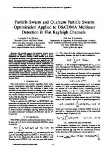
When a single Bezier curve is used for trajectory planning, there are several reasons why it may not be able to converge into a suitable trajectory for a trolley’s displacement. A Bezier curve constructed from numerous control points is numerically unstable; and moving one control point can alter the global shape of the curve. To overcome this problem, the entire Bezier curve is constructed though smoothly connecting several piecewise Bezier curves. In order to make the Bezier curve continuous and smooth at the connection points, we mainly focused on assuring the continuity of the first-order derivative and secondorder derivative at the waypoints connecting the two curves. Figure 2 gives an example of the displacement for a trolley curve connected by two Bezier curves. The abscissa is time, and the vertical coordinate is the displacement of the trolley. The points in Figure 2 are the control points of the Bezier curve, and the vertical coordinates of each control point can be changed to generate a Bezier curve with a different shape, so as to obtain different acceleration curves for the trolley. The two curves meet at a shared end point, termed the curve “midpoint”. In order to ensure that the curve is smooth at the midpoint, the velocity and acceleration of the trolley at the midpoint of the two piecewise Bezier curves need to be equal. According to (12)∼(15), we can obtain 𝑁 𝑁 (𝑃𝑁 − 𝑃𝑁−1 ) = (𝑃 − 𝑃𝑁) 𝑇1 𝑇1 𝑁+1 𝑁 (𝑁 − 1) (𝑃𝑁 − 2𝑃𝑁−1 + 𝑃𝑁−2 ) 𝑇12 𝑁 (𝑁 − 1) (𝑃𝑁+2 − 2𝑃𝑁+1 + 𝑃𝑁) = 𝑇12
⋅ (𝑃𝑖+2 − 2𝑃𝑖+1 + 𝑃𝑖 )
(16)
(17)
𝑥̇ (𝑡𝑠 ) =
𝑁 (𝑃 − 𝑃0 ) 𝑇1 1
(12)
For a curve constructed of 𝑛 segments Bezier curves and where the second-order derivative is continuous, 𝑛(N3)+3 points are needed to shape the curve. As every point has two parameters, which includes the abscissa values and the ordinate values, 2n(N-3)+6 independent parameters are required for this kind of Bezier curve. The shape of the Bezier curve is significantly affected by the position of the control points (𝑃0 , 𝑃1 , ⋅ ⋅ ⋅ , 𝑃𝑁). The Bezier curve is generated as the trolley displacement and trolley acceleration can be calculated according to its displacement as in (9) and (11). Meanwhile, the residual swing of the payload is calculated by the trolley’s acceleration according to (8). In other words, the residual swing of the payload 𝜃 is a function of the control points (𝑃0 , 𝑃1 , ⋅ ⋅ ⋅ , 𝑃𝑁), which can be defined as 𝜃(𝑃0 , 𝑃1 , ⋅ ⋅ ⋅ , 𝑃𝑁), and the residual swing of the payload can be suppressed through generating suitable control points on the Bezier curve.
𝑥̇ (𝑡𝑒 ) =
𝑁 (𝑃 − 𝑃𝑁−1 ) 𝑇1 𝑁
(13)
3.2. The Constraints and Cost Functions of Trajectory Planning
𝑖 = 𝑁!/(𝑁 − 𝑖)!𝑖! is the binomial coefficient of order where 𝐶𝑁 𝑁. The following properties of Bezier curves render them particularly suitable for trajectory generation: (1) Bezier curves start at the first point 𝑃0 and end at the last point 𝑃𝑁. They are continuous at any degree. (2) The vectors tangential to the Bezier curves at the start and end points are parallel to the line that connects the first two (𝑃0 and 𝑃1 ) and last two control points (𝑃𝑁 and 𝑃𝑁−1 ), respectively. According to (10) and (11), the velocity and acceleration of the trolley at the start point 𝑃0 and the end point 𝑃𝑁 are
𝑁 (𝑁 − 1) 𝑥̈ (𝑡𝑠 ) = (𝑃2 − 2𝑃1 + 𝑃0 ) 𝑇12 𝑥̈ (𝑡𝑒 ) =
𝑁 (𝑁 − 1) (𝑃𝑁 − 2𝑃𝑁−1 + 𝑃𝑁−2 ) 𝑇12
(14)
(15)
3.2.1. Constraints. According to the practical experience of operating an overhead crane, the following constraints need to be considered when carrying out trajectory planning for the trolley. The trolley reaches the desired location 𝑝𝑑 within a finite time 𝑡𝑒 . The maximum permitted payload swing, trolley velocity, and trolley acceleration all need to be kept within
Mathematical Problems in Engineering
5
acceptable limits. There should be no swing when the trolley stops at the destination. That is, 𝑥 (𝑡𝑒 ) = 𝑝𝑑 ,
∀𝑡 ≥ 𝑡𝑒
|𝑥̇ (𝑡)| ≤ Vmax , |𝑥̈ (𝑡)| ≤ 𝑎max |𝜃 (𝑡)| ≤ 𝜃max
(18)
𝜃 (𝑡𝑒 ) = 0, 𝑥̈ (𝑡𝑒 ) = 0 Vmax and 𝑎max are the permitted maximum velocity and the acceleration of trolley, respectively. 𝜃max is the maximum allowable swing amplitude. 3.2.2. Objective Functions. The energy of the payload is an important indicator for evaluating payload swing. The kinetic energy and potential energy of the payload are 2 1 𝐸 = 𝑚𝑝 (𝑙𝜃)̇ + 𝑚𝑝 𝑔𝑙 (1 − cos 𝜃) 2
(19)
𝐸 𝑙 2̇ = 𝜃 + (1 − cos 𝜃) 𝑚𝑝 𝑔𝑙 2𝑔
𝑗
global position 𝑔𝑖,𝑏𝑒𝑠𝑡 . Their updates can be expressed as follows as determined by the PSO algorithm: 𝑗+1
V𝑖
𝑗+1 𝑝𝑖
(20)
The objective function of trajectory planning is to ensure safety during the horizontal transportation of the payload. The safety of an overhead crane can be reflected in the following three metrics: the maximum swing angle of the payload, the mean swing angle of the payload, and the normalized energy of the payload at the finish time 𝑡𝑒 . The objective function which combines three of the metrics is 𝐽 (𝑃0 , 𝑃1 , ⋅ ⋅ ⋅ , 𝑃𝑁) = min {𝑎 max 𝜃𝑖 (𝑃0 , 𝑃1 , ⋅ ⋅ ⋅ , 𝑃𝑁) 𝑖∈{1,2,⋅⋅⋅ ,𝑘}
Suppose the position and the velocity of the 𝑖th particle 𝑗 𝑗 at iteration j are represented by 𝑝𝑖 and V𝑖 , respectively. The th update velocity of the 𝑖 particle then consists of three 𝑗 parts: a momentum of its previous velocity V𝑖 , velocity 𝑗 increments according to its best local 𝑝𝑖,𝑏𝑒𝑠𝑡 , and the best
𝑗
𝑗
𝑗
𝑗
𝑗
= 𝑤V𝑖 + 𝑐1 𝑟1 (𝑝𝑖,𝑏𝑒𝑠𝑡 − 𝑝𝑖 ) + 𝑐2 𝑟2 (𝑔𝑖,𝑏𝑒𝑠𝑡 − 𝑝𝑖 ) (22)
The normalized total energy of the payload is 𝐸=
(𝑃0 , 𝑃1 , ⋅ ⋅ ⋅ , 𝑃𝑁) on the Bezier curve. Particle swarm optimization is an evolutionary computation technique. The standard PSO algorithm consists of three steps: (1) First, initialize a population of particles (𝑃0 , 𝑃1 , ⋅ ⋅ ⋅ , 𝑃𝑁) with random initial values within the solution space. (2) Evaluate the optimization fitness function 𝐽(𝑃0 , 𝑃1 , ⋅ ⋅ ⋅ , 𝑃𝑁): the movements of the particles are guided based on the information of their own current best known position (local) and the swarm’s current best known position (global). When better positions are found, these will then be chosen to lead the movement of the swarm. (3) This process is repeated generation by generation until satisfactory control points (𝑃0 , 𝑃1 , ⋅ ⋅ ⋅ , 𝑃𝑁) on the Bezier curve are eventually found.
(21)
𝜃𝑖 (𝑃0 , 𝑃1 , ⋅ ⋅ ⋅ , 𝑃𝑁) + 𝛽𝐸 (𝑘)} + (1 − 𝑎) ∑ 𝑘 𝑖=1 𝑘
𝑘 is the number of samples in the evaluated planning period. 𝜃𝑖 (𝑃0 , 𝑃1 , ⋅ ⋅ ⋅ , 𝑃𝑁) is the payload swing angle at the 𝑖𝑡ℎ period when the control points on the Bezier curve are (𝑃0 , 𝑃1 , ⋅ ⋅ ⋅ , 𝑃𝑁). The first component is the maximum swing angle, and the second component is the mean swing angle of the payload. The third component guarantees the value of the payload’s swing angle is kept small when the trolley moves to the desired location. The weight coefficient 𝑎 is set at 0.5 in this paper, and the weight coefficient 𝛽 is set at 25. The optimal variables are the control point’s locations (𝑃0 , 𝑃1 , ⋅ ⋅ ⋅ , 𝑃𝑁) on the Bezier curve. 3.3. Particle Swarm Optimization. Particle swarm optimization (PSO) is used to find the optimal control points
=
𝑗 𝑝𝑖
+
𝑗+1 V𝑖 ,
𝑖 = 1, 2, ⋅ ⋅ ⋅ , 𝑚
where 𝑚 is the size of the populations. 𝑐1 and 𝑐2 are positive constants called learning factors and 𝑟1 and 𝑟2 are the uniformly distributed values in the interval [0, 1]. The coefficient 𝑤 is an inertia weight factor which effectively controls the scope of the search. A lower inertia weight leads to better exploitation, whilst a higher inertia weight implies better exploration of new search areas. Thus, the linear decrease of inertia weight from 0.9 to 0.4 during iteration ensures an efficient balancing between the global and local search. 3.4. Combining the Particle Swarm Optimization Algorithm and the Bezier Curve Method. The trolley’s displacement is generated by a Bezier curve as shown in Figure 2. The points in Figure 2 are the control points for the Bezier curve, and the vertical coordinate values of each of the control points can be changed to generate a Bezier curve with a different shape, so as to obtain different acceleration curves for the trolley. The particle swarm optimization algorithm is then used to optimize the shape of the Bezier curve from the initial population until the optimization process results can satisfy the given constraints. Trajectory planning for a trolley means finding a suitable displacement curve that will move an object from an initial position to the target position while satisfying certain constraints. In this paper, displacement curves are randomly directly generated through using the Bezier curve method, and then the PSO algorithm is used to obtain the optimum displacement curve which satisfies certain constraints. This hybrid optimization algorithm, which combines the PSO algorithm with the Bezier curve method, is abbreviated as the “PSO-BC” in this paper. The steps detailing this are summarized below.
6
Mathematical Problems in Engineering 3
The second segment Bezier curve
The first segment Bezier curve
Displacement of trolley (m)
PN+1 2 PN
1 0
Step 6. Obtain the optimal flat output variables 𝑔𝑖,𝑏𝑒𝑠𝑡 . Then, use those control points to generate the Bezier curve as the displacement curve for the trolley. Substitute the optimal Bezier curve into the system’s dynamic equation (8) and obtain the actual payload swing angle 𝜃(𝑃0 , 𝑃1 , ⋅ ⋅ ⋅ , 𝑃𝑁) using numerical integral calculations.
midpoint PN−1
−1
PN−2 PN+2
−2 0
2
4
6
8
do not satisfy the precision requirement, then increase the number of Bezier curve control points, and go to Step 2, or else stop. This process is repeated generation by generation until a satisfactory solution 𝑔𝑖,𝑏𝑒𝑠𝑡 (𝑃0 , 𝑃1 , ⋅ ⋅ ⋅ , 𝑃𝑁) is eventually discovered.
10
time (s) Bezier curve control point
Figure 2: The displacement curve of a trolley connected by two piecewise Bezier curves.
4. Numerical Simulation In this section, some numerical simulations were carried out to verify the validity of the proposed PSO-BC trajectory planning scheme. The physical parameters of the simulated overhead system were listed as follows: 𝑚𝑝 = 1.025 𝑘𝑔,
Step 1. Rewrite the original problem equation (3) in a flat output space as (4) and then discretize the dynamic equation as in (8). The residual swing of the payload is affected by acceleration curve of the trolley. Step 2. The control points of the Bezier curve (𝑃0 , 𝑃1 , ⋅ ⋅ ⋅ , 𝑃𝑁) are stochastically generated, and the Bezier curve is generated as the displacement curve of the trolley. The trolley’s acceleration can be obtained using the second-order derivative with respect to time for the trolley’s displacement, as in (11). In addition, the trolley’s acceleration is used as an input signal in (8). When the positions of the control points are moved, the shapes of acceleration curve of trolley also change. Step 3. The control points of the Bezier curves are used as particles in the PSO algorithm. The size of the populations and the maximum number of iterations 𝑖𝑡𝑒𝑟max are given. The stopping criterion is whether the change between the current best particle fitness value and its previous one is smaller than a predefined value 𝜅. Step 4. Several constraints in (18) need to be satisfied when carrying out trajectory planning for the trolley. If these constraints are not met, the control points of Bezier curve need to be moved to make sure the trolley’s acceleration meets these constraints. The swing angle of the payload 𝜃𝑖 (𝑃0 , 𝑃1 , ⋅ ⋅ ⋅ , 𝑃𝑁) can be calculated according to (8). The objective function 𝐽(𝑃0 , 𝑃1 , ⋅ ⋅ ⋅ , 𝑃𝑁) which combines the maximum swing angle, the mean swing angle, and the normalized energy can be calculated as (21). Step 5. In order to obtain optimal results, Particle Swarm Optimization is used to adjust the positions of the control points of the Bezier curve until the best control points are 𝑗 found. The best fitness value 𝑔𝑖,𝑏𝑒𝑠𝑡 needs to be compared 𝑗−1
with its previous one 𝑔𝑖,𝑏𝑒𝑠𝑡 ; if the change between the two is smaller than 𝜅, then go to Step 6. If the results
𝑚𝑐 = 7 𝑘𝑔, 𝑙 = 0.75 𝑚,
(23)
𝑔 = 9.8 𝑚/𝑠2 The desired trolley location 𝑝𝑑 in the simulation ranged from 0.6m to 4 m, and the practical constraints were given as Vmax = 0.4 𝑚/𝑠, 𝑎max = 1.2 𝑚/𝑠2 , 𝜃max = 5 deg,
(24)
𝑡𝑠 = 0 𝑠, 𝑡𝑓 = 10 𝑠. The trolley’s displacement was generated using a fifthorder Bezier curve with 6 control points (𝑃0 , 𝑃1 , 𝑃2 , 𝑃3 , 𝑃4 , 𝑃5 ). In this paper, we connected 4 segments of the Bezier curves to create the trolley’s displacement curve, and the total number of control points for the Bezier curve was 21. The parameters involved for the PSO-BC were listed as follows: the population size for the simulation experiments was fixed at 100, and 𝑖𝑡𝑒𝑟max = 50, 𝑐1 = 𝑐2 = 2, Table 1 gives the optimized control point positions of the Bezier curve when the initial swing angle 𝜃0 and the desired location 𝑝𝑑 are given values. Take the first row as an example: when the desired location of the trolley is 0.6 meters and the initial swing angle of the payload is -0.087 rad, then the control points of the optimal Bezier curve are (0, 0, 0, 0.065, 0, 0.055, 0.109, 0.283, 0.600, 0.461, 0.600, 0.739, 1.155, 0.045, 0.177, 0.322, 0.467, 0.626, 0.6, 0.6, 0.6). Figure 3 shows the corresponding simulation results when the desired location of trolley is at 0.6 m and the initial swing angle of payload is set to zero. Figure 3(a) is the optimized displacement of the trolley which is generated by
𝑝𝑑 (m) 0.6 1 1.4 1.8 2.2 2.6 3 3.4 3.8 4 0.6 1 1.4 1.8 2.2 2.6 3 3.4 3.8 4
𝜃0 (rad) -0.087 -0.087 -0.087 -0.087 -0.087 -0.087 -0.087 -0.087 -0.087 -0.087 0 0 0 0 0 0 0 0 0 0
Control points of the optimal Bezier curve 𝑔𝑏𝑒𝑠𝑡 (𝑃1 , 𝑃2 , ..., 𝑃21 ) (0, 0, 0, 0.065, 0, 0.055, 0.109, 0.283, 0.600, 0.461, 0.600, 0.739, 1.155, 0.045, 0.177, 0.322, 0.467, 0.626, 0.6, 0.6, 0.6) (0, 0, 0.091, -0.223, -0.018, 0.278, 0.574, 0.96, 0.449, 0.66, 0.79, 0.920, 0.970, 0.754, 0.907, 0.808, 0.710, 0.361, 0.875, 1, 1) (0, 0.005, 0, 0, 0.281, 0.440, 0.599, 0.635, 1.400, 1.400, 1.400, 1.400, 1.400, 1.400, 1.400, 1.400, 1.400, 1.400, 1.4, 1.4, 1.4) (0, 0.009, 0, 0, 0.096, 0.516, 0.935, 1.678, 0.924, 1.363, 1.589, 1.814, 1.826, 1.800, 1.799, 1.800, 1.801, 1.803, 1.8, 1.8, 1.8) (0, 0, 0, 0, 0.016, 0.424, 0.832, 1.634, 1.354, 1.588, 1.711, 1.835, 1.850, 2.200, 2.200, 2.194, 2.187, 2.175, 2.2, 2.2, 2.2) (0, 0, 0, 0, 0, 0.332, 0.663, 1.326, 1.313, 1.368, 1.578, 1.788, 2.153, 2.367, 2.104, 2.171, 2.237, 2.634, 2.6, 2.6, 2.6) (0, 0, 0, 0, 0.239, 0.746, 1.253, 2.028, 1.371, 1.824, 2.177, 2.530, 2.782, 2.926, 2.787, 2.809, 2.830, 3.014, 3, 3, 3) (0, 0.3, 0, 0.877, 1.004, 1.509, 2.013, 2.895, 0.661, 3.171, 3.400, 3.629, 1.578, 3.4, 3.4, 3.4, 3.4, 3.4, 3.4, 3.4, 3.4) (0, 0, 0.001, 0, 0.145, 0.515, 0.886, 1.483, 1.844, 1.764, 2.103, 2.441, 3.199, 3.304, 2.975, 3.114, 3.253, 3.861, 3.8, 3.8, 3.8) (0, 0, 0, 0.886, 0.927, 1.055, 1.183, 1.397, 1.713, 2.040, 2.468, 2.897, 3.428, 3.196, 2.839, 2.874, 2.909, 3.337, 4, 4, 4) (0, 0, 0.132, 0, 0.108, 0.162, 0.217, 0.217, 0.331, 0.381, 0.426, 0.471, 0.511, 0.581, 0.579, 0.600, 0.621, 0.664, 0.6, 0.6, 0.6) (0, 0.056, 0.113, 0.167, 0.227, 0.29, 0.353, 0.419, 0.518, 0.531, 0.6, 0.671, 0.799, 0.715, 0.828, 0.867, 0.907, 0.874, 1, 1, 1) (0, 0, 0, 0.026, 0, 0.048, 0.097, 0.220, 0.257, 0.413, 0.494, 0.574, 0.579, 0.983, 0.981, 1.040, 1.099, 1.219, 1.4, 1.4, 1.4) (0, 0.13, 0.271, 0.444, 0.541, 0.688, 0.835, 1.033, 1, 1.201, 1.314, 1.426, 1.47, 1.644, 1.647, 1.678, 1.7, 1.768, 1.8, 1.8, 1.8) (0, 0.24, 0.446, 0.687, 1.03, 1.152, 1.272, 1.165, 2.2, 1.743, 1.863, 1.983, 2.679, 1.74, 2.08, 2.187, 2.29, 2.168, 2.2, 2.2, 2.2) (0, 0.19, 0.38, 0.599, 0.756, 0.96, 1.168, 1.423, 1.523, 1.705, 1.855, 2, 2.123, 2.308, 2.354, 2.41, 2.469, 2.538, 2.6, 2.6, 2.6) (0, 0.411, 0.832, 1.149, 1.503, 1.787, 2.071, 2.286, 2.636, 2.637, 2.750, 2.862, 3.087, 2.998, 3, 3, 3, 2.998, 3, 3, 3) (0, 0.359, 0.717, 1.047, 1.457, 1.68, 1.905, 1.94, 3.185, 2.642, 2.83, 3.02, 3.942, 2.58, 3.235, 3.4, 3.565, 3.239, 3.4, 3.4, 3.4) (0, 0.466, 1.07, 0.688, 1.887, 2.15, 2.418, 1.749, 3.754, 3.04, 3.295, 3.546, 4.759, 2.714, 3.543, 3.78, 4, 3.667, 3.8, 3.8, 3.8) (0, 0.393, 0.718, 1.23, 1.498, 1.907, 2.316, 2.866, 2.647, 3.142, 3.399, 3.657, 3.677, 4, 3.930, 3.999, 4.069, 4.277, 4, 4, 4)
Table 1: The control points of the optimal Bezier curve.
Mathematical Problems in Engineering 7
0.6 0.4 0.2 0.0 0.0
2.5
5.0 time (sec)
7.5
10.0
acceleration (m/M2 )
Mathematical Problems in Engineering displacement (m)
8 0.4 0.2 0.0 −0.2 0.0
2.5
5.0 time (sec)
7.5
10.0
displacement control points (b)
angle (deg)
0.4 0.2 0.0 −0.2 −0.4 0.0
2.5
5.0
7.5
10.0
time (sec) (c)
normalized energy
(a)
0.0003 0.0002 0.0001 0.0000 0.0
2.5
5.0 time (sec)
7.5
10.0
(d)
Figure 3: The results of the proposed trajectory planning for when the desired location of the trolley is set at 0.6m. (a) The trolley’s displacement and control points of the Bezier curve; (b) the trolley’s acceleration; (c) the swing angle of the payload; (d) the normalized energy of the payload.
the control points of the Bezier curve. The initial location of trolley is zero, and the desired location of trolley is 0.6 m. The red square points are the control points of the Bezier curve. The PSO-BC algorithm successfully found a solution 𝑔𝑏𝑒𝑠𝑡 [0, 0, 0.132, 0, 0.108, 0.162, 0.217, 0.217, 0.331, 0.381, 0.426, 0.471, 0.511, 0.582, 0.579, 0.600, 0.621, 0.664, 0.6, 0.6, 0.6] that fulfils all the constraints. It is made up of four sections of the five-order Bezier curve. Figure 3(b) is the acceleration of the trolley calculated using (11), and the acceleration of the trolley is continuous at every midpoint. Figure 3(c) is the swing angle of the payload; the initial swing angle is zero, and the final swing angle is zero. There is no residual swing when the trolley stops at the destination. Figure 3(d) is the normalized energy of the payload which is an indicator of the swing energy of payload. The normalized energy of the payload rises dramatically at the beginning and drops down to zero when the trolley moves to the desired location. Figure 4 shows the corresponding simulation results when the desired location of the trolley is at 4 m and the initial swing angle of the payload is at 5 degrees. The red square points of Bezier curve are [0, 0, 0, 0.886, 0.927, 1.055, 1.183, 1.397, 1.713, 2.040, 2.468,2.897, 3.428, 3.196, 2.839, 2.874, 2.909, 3.337, 4, 4, 4]. At the beginning, the normalized energy of the payload is quite large, because the payload has an initial angle as shown in Figure 4(c). The normalized energy of the payload drops rapidly when the trolley moves to the desired location. Figure 5 shows the convergences of the best fitness functions versus the number of iterations for the two PSO simulations. The fitness values decrease fairly rapidly which shows the searching power of the PSO-BC algorithm.
We presented two groups of numerical simulation results for the proposed PSO-BC scheme, as compared to existing approaches such as the online trajectory generating method (OTGM) [16] and the phase plane-based trajectory planning method (PPBM) [15]. The phase plane-based planning method (PPBM) does not take into account the bounded jerk constraint. For the first simulation, we supposed that the initial angle of the payload was zero. Figure 6 shows a comparison of the simulation results for the various methods, which includes the OTGM, PPBM, and the proposed PSO-BC methods. Figure 6(a) shows the trolley displacement graphs for the three input signals. Figure 6(b) depicts the acceleration graphs for the trolleys. Figure 6(c) shows the payload swing angle curve graphs where the residual oscillations of the payloads are essentially suppressed after 10 seconds. Figure 6(d) shows the normalized energy change diagrams for the payloads, where the energies of the payloads are suppressed after 10 seconds of oscillation. It is clearly seen that all the trolleys reach their target positions accurately and the maximum accelerations of the trolleys are kept under the physical constraints during the overall transfer processes. It is also seen that the maximum payload swing angles never exceed the permitted range of 5 degrees, and there is no residual swinging when the trolley stops at the destination. However, it should be noted that although the PPBM control system shows the fastest convergence speed to the desired location, its maximum swing angle is larger than those of the other two methods during the planning process. The normalized energy graph of the PPBM control system in Figure 6(d) has four peaks which are nearly twice as large as the proposed PSOBC method.
5 4 3 2 1 0 0.0
9 1.2
acceleration (m/M2 )
displacement (m)
Mathematical Problems in Engineering
2.5
5.0 time (sec)
7.5
0.6 0.0 −0.6 −1.2 0.0
10.0
2.5
5.0 time (sec)
7.5
10.0
displacement control points (b)
(a)
normalized energy
angle (deg)
5.0 2.5 0.0 −2.5 −5.0 0.0
2.5
5.0 time (sec)
7.5
10.0
0.0039 0.0026 0.0013 0.0000 0.0
2.5
5.0 time (sec)
7.5
10.0
(d)
(c)
Figure 4: The results of the proposed trajectory planning for when the desired location of trolley is set at 4m. (a) The trolley’s displacement and control points on the Bezier curve; (b) the trolley’s acceleration; (c) the swing angle of the payload; (d) the normalized energy of the payload.
1.8
0.035
1.6 Global best objective value
Global best objective value
0.030 0.025 0.020 0.015 0.010 0.005
1.4 1.2 1.0 0.8 0.6 0.4 0.2 0.0
0.000 0
10
20 30 Iteration number
40
(a)
50
0
10
20 30 Iteration number
40
50
(b)
Figure 5: The convergence of the best fitness evaluations (a) for when the desired location of the trolley is 𝑝𝑑 = 0.6𝑚 and the initial angle is zero and (b) for when the desired location of the trolley is 𝑝𝑑 = 4𝑚 and the initial angle is 5 degrees.
Similarly, Figure 7 shows the simulation results for the three input signals when the trolley’s desired position is at 1 meter. The control points for the optimal Bezier curve are (0, 0.056, 0.113, 0.167, 0.227, 0.29, 0.353, 0.419, 0.518, 0.531, 0.6, 0.671, 0.799, 0.715, 0.828, 0.867, 0.907, 0.874, 1, 1, 1). In Figure 7(a), all the three control methods reach the desired position, but the OTGM, PPBM methods are faster than the proposed PSO-BC method. The trolley’s acceleration in the proposed PSO-BC method is larger than that of the other two input signals for a short time. Figures 7(c) and 7(d) indicate that the maximum angle of the payload and the
normalized energy graph for the proposed PSO-BC method is much smaller than that of the OTGM and PPBM methods, respectively. For each compared trajectory in Figures 6 and 7, the results for the maximum swing angles and the average swing angles are listed in Table 2. The first three columns of Table 2 are the results for when the desired position of trolley is at 3 meters. The second three columns of Table 2 are the results for when the desired position of trolley is at 1 meter. It is seen that when the same state and control constraints are used, the proposed PSO-BC method is more efficient than that of
3 2 1 0 0
2
4
6
8
10
Time (s)
Acceleration of trolley (m/M2 )
Mathematical Problems in Engineering Displacement of trolley (m)
10
1.0 0.5 0.0 −0.5 −1.0 0
2
4
6
8
10
Time (s)
PSO-BC OTGM PPBM (a)
(b)
Normalized energy
Angle (deg)
5.0 2.5 0.0 −2.5 −5.0 0
2
4
6
8
0.015 0.010 0.005 0.000
10
0
2
4
6
Time (s)
8
10
Time (s)
(c)
(d)
1.2 0.9 0.6 0.3 0.0 0
2
4
6
8
10
Time (s)
Acceleration of trolley (m/M2 )
Displacement of trolley (m)
Figure 6: A comparison of the proposed methods and the existing approaches for when the desired location of the trolley is at 3m. (a) The trolley displacements and the control points of the Bezier curves; (b) the trolley accelerations; (c) the swing angles of the payloads; (d) the normalized energies of the payloads.
1.0 0.5 0.0 −0.5 −1.0 0
2
4
6
8
10
6
8
10
Time (s)
PSO-BC KCTPM PPBM (a)
(b)
Normalized energy
Angle (deg)
5.0 2.5 0.0 −2.5 −5.0 0
2
4
6
8
10
0.003 0.002 0.001 0.000 0
2
4
Time (s)
Time (s)
(c)
(d)
Figure 7: A comparison of the proposed methods and the existing approaches for when the desired location of trolley is at 1m. (a) The trolley displacements and control points of the Bezier curves; (b) the trolley accelerations; (c) the swing angles of the payloads; (d) the normalized energies of the payloads. Table 2: A comparison of the maximum swing angles and average angles. trajectory Maximum swing angle (rad) Average angle (rad)
PSO-BC 0.0494 0.0249
OTGM 0.0882 0.0247
PPBM 0.0872 0.0194
PSO-BC∗ 0.0136 0.0047
OTGM∗ 0.0363 0.0089
PPBM∗ 0.0872 0.0193
11
3 2 1 0 0
2
4
6
8
10
Time (s)
Acceleration of trolley (m/M2 )
Displacement of trolley (m)
Mathematical Problems in Engineering
1.0 0.5 0.0 −0.5 −1.0 0
2
4
6
8
10
6
8
10
Time (s)
PSO-BC OTGM (a)
Angle (deg)
3 0 −3 −6 0
2
4
6
8
10
Time (s) (c)
Normalized energy
(b)
6
0.015 0.010 0.005 0.000 0
2
4 Time (s) (d)
Figure 8: A comparison of the proposed methods and the existing approaches for when the desired location of the trolley is set at 3m. (a) The trolley displacements and control points of the Bezier curves; (b) the trolley accelerations; (c) the swing angles of the payloads; (d) the normalized energies of the payloads.
the other two methods and its optimal-swing trajectory has the smallest maximal swing angle of 0.0136 rad. Although the average swing of its optimal 3-meter trajectory is larger than the OTGM and PPBM methods, the maximum swing value of the PSO-BC method is the smallest amongst the compared trajectories. To further verify that the proposed PSO-BC method works well for any initial state, we carried out a second simulation for when the initial swing angles were not set at zero. The initial configurations were selected as 𝑞0 = [0, 0, 5(deg), 0] and the other constraints were the same as those in (18). The PPBM method was unable to be directly used when the initial swing angle was not zero and so only the OTGM and the proposed PSO-BC methods were compared. Figure 8 depicts the simulation results for the positions of the trolley, the trolley accelerations, the swing angles of the payloads, and the normalized energies of the payloads. Both the proposed PSO-BC method and the OTGM method were successful in reaching the target configurations when there were different starting angles. Figure 8(a) shows that the trolley using the OTGM method reached the destination position much faster than that of the proposed PSO-BC method. As shown in Figure 8(d), the normalized energy peak for the OTGM method was larger than that of the proposed PSO-BC method. This simulation demonstrates that the proposed approach could potentially act as an online trajectory planner, for when the initial state was a nonstatic system state. It is promising that, in a real-time online implementation of the proposed PSO-BC method, it is able to suppress payload swing. Figure 9 shows the simulation results for when the trolleys desired position was set at 1 meter and the initial swing
angle was negative 5 degrees. The control points of the PSOBC method are (0, 0, 0.091, -0.223, -0.018, 0.278, 0.574, 0.960, 0.449, 0.660, 0.790, 0.920, 0.970, 0.754, 0.907, 0.808, 0.710, 0.361, 0.875, 1, 1). Figure 9(b) shows that the trolley’s acceleration in the OTGM method was smoother than that of the proposed PSO-BC method. In Figure 9(d), the maximum normalized energy of the OTGM method was larger than that of the proposed PSO-BC method. The OTGM method and the proposed PSO-BC method are two different control schemes for trolley trajectory planning, each having its own set of advantages and disadvantages. For the OTGM method, the trajectory commands are generated and applied to the system in real time. However, these control methods need accurate sensors to measure the trolley positions and velocities as well as the payload swing angles. In general, it is quite difficult to measure all this data in real time in an outdoor environment due to the vibrations of the overhead cranes. For the proposed PSO-BC method, the trajectory commands are calculated in advance of implementation. The advantages of this are that the trolley’s stopping time can be set as a parameter, and variables, such as payload swing angle and trolley acceleration, can be limited during the whole control process. Increasing the number of segments of the Bezier curves means that the curves can be used for more complex control methods. However, doing this will also increase the burden on the computer, as it will take longer to generate the multisegments of the Bezier curves. Meanwhile, the intelligent optimization algorithm should avoid falling for any local optimal solutions. In Figures 6–8, the proposed PSO-BC method performed better than the OTGM method when measured by the normalized energy indicator but was worse in the trolley
1.2 0.8 0.4 0.0 0
2
4
6
8
10
Time (s)
Acceleration of trolley (m/M2 )
Mathematical Problems in Engineering Displacement of trolley (m)
12
1.0 0.5 0.0 −0.5 −1.0 0
2
4
6
8
10
Time (s)
PSO-BC OTGM (a)
Angle (deg)
2.5 0.0 −2.5 −5.0 0
2
4
6
8
10
Normalized energy
(b)
5.0
0.008 0.004 0.000 0
2
Time (s)
4
6
8
10
Time (s)
(c)
(d)
Figure 9: A comparison of the proposed methods and the existing approaches for when the desired locations of the trolleys are set at 1m. (a) The trolley displacements and control points of Bezier curves; (b) the trolley accelerations; (c) the swing angles of the payloads; (d) the normalized energies of the payloads.
acceleration indicator measurement. This occurred because the objective function in (21) only combines three of the indicators: the mean swing angle of the payload, the maximum swing angle, and the normalized energy of the payload. Additionally, the proposed PSO-BC method performed better than the OTGM method in last two indicator measurements as seen in Figures 6–8. In future studies, other indicators should be added to the objective function in (21) to make the proposed PSO-BC method perform better.
5. Conclusion This paper proposed a trajectory planning method based on the Bezier curve and particle swarm optimization to suppress payload swing. A five-order Bezier curve was used to generate the trolley’s displacement. The desired position of the trolley was set at the last control point in the Bezier curve, which guaranteed that the trolley would reach the desired position accurately. Furthermore, the acceleration of the trolley, which is a second-order derivative with respect to time 𝑡 of the trolley’s displacement, was used as the input signal for the system. In order to make the Bezier curve more numerically stable, the entire Bezier curve was constructed from smoothly connected piecewise Bezier curves. The shape of the trolley’s displacement would also change whenever the control points on the Bezier curve changed their position. Particle swarm optimization was then used to find the optimal control points on the Bezier curve to make the trolley reach the desired position whilst suppressing the payload’s swing under the trolley’s velocity and acceleration constraints. Simulation results with comparisons to existing approaches were then
presented to show the superior performance of the proposed PSO-BC method. The main results and conclusions were as follows: (1) The desired position of the trolley was set as the last control point of the Bezier curve, which ensured that the trolley reached its desired position accurately. (2) Using the control points of the Bezier curve as the swarm in the particle swarm optimization process meant that the optimized Bezier curve of the trolley’s displacement was found by the particle swarm optimization method which satisfied constraints such as velocity or acceleration limits. The trolley was able to be moved to its desired position accurately whilst its payload’s swing angle was kept to a minimum. (3) Each optimization result could be stored as a data source, which could then be used as an initial parameter on the list of Bezier curve control points. As data sources increase, the iterative process of the particle swarm optimization process will become faster and faster. As the initial state could be any nonstatic system state, it would therefore be possible to implement the proposed PSO-BC method in realtime online.
Data Availability The data used to support the findings of this study are available from the corresponding author upon request.
Mathematical Problems in Engineering
13
Conflicts of Interest The authors declare that there are no conflicts of interest as regards the publication of this paper.
Acknowledgments
[15]
[16]
The authors are enormously grateful for the support of the National Natural Science Foundation of China (Grants no. 51175442 and no. 51205328) and the applied basic research projects of Sichuan, China, under Grant no. 2013JY0136.
[17]
References
[18]
[1] E. M. Abdel-Rahman, A. H. Nayfeh, and Z. N. Masoud, “Dynamics and control of cranes: a review,” Journal of Vibration and Control, vol. 9, no. 7, pp. 863–908, 2003. [2] K. Kecik and M. Borowiec, “An autoparametric energy harvester,” The European Physical Journal Special Topics, vol. 222, no. 7, pp. 1597–1605, 2013. [3] L. Ramli, Z. Mohamed, A. M. Abdullahi, H. Jaafar, and I. M. Lazim, “Control strategies for crane systems: A comprehensive review,” Mechanical Systems and Signal Processing, vol. 85, pp. 1–23, 2017. [4] W. Singhose, “Command shaping for flexible systems: a review of the first 50 years,” International Journal of Precision Engineering and Manufacturing, vol. 10, no. 4, pp. 153–168, 2009. [5] N. Sun, Y. Fang, and X. Zhang, “Energy coupling output feedback control of 4-DOF underactuated cranes with saturated inputs,” Automatica, vol. 49, no. 5, pp. 1318–1325, 2013. [6] M. I. Solihin, Wahyudi, and A. Legowo, “Fuzzy-tuned PID antiswing control of automatic gantry crane,” Journal of Vibration and Control, vol. 16, no. 1, pp. 127–145, 2010. [7] D.-H. Kim and J.-W. Lee, “Model-based PID control of a crane spreader by four auxiliary cables,” Proceedings of the Institution of Mechanical Engineers - Part C: Journal of Mechanical Engineering Science, vol. 220, no. 8, pp. 1151–1165, 2006. [8] R. Mar, A. Goyal, V. Nguyen, T. Yang, and W. Singhose, “Combined input shaping and feedback control for doublependulum systems,” Mechanical Systems and Signal Processing, vol. 85, pp. 267–277, 2017. [9] L.-H. Lee, P.-H. Huang, S.-T. Pan, H. W. Lie, T.-C. Chiang, and C.-Y. Chang, “Applying vision feedback to crane controller design,” International Journal of Systems Science, vol. 46, no. 2, pp. 294–302, 2015. [10] W. Singhose, W. Seering, and N. Singer, “Residual vibration reduction using vector diagrams to generate shaped inputs,” Journal of Mechanical Design, vol. 116, no. 2, pp. 654–659, 1994. [11] Z. N. Masoud and K. A. Alhazza, “Frequency-modulation input shaping control of double- pendulum overhead cranes,” Journal of Dynamic Systems Measurement and Control-Transactions of the ASME, vol. 136, no. 2, 2014. [12] X. Xie, J. Huang, and Z. Liang, “Vibration reduction for flexible systems by command smoothing,” Mechanical Systems and Signal Processing, vol. 39, no. 1-2, pp. 461–470, 2013. [13] N. Q. Hoang, S.-G. Lee, H. Kim, and S.-C. Moon, “Trajectory planning for overhead crane by trolley acceleration shaping,” Journal of Mechanical Science and Technology, vol. 28, no. 7, pp. 2879–2888, 2014. [14] P. Boscariol and D. Richiedei, “Robust point-to-point trajectory planning for nonlinear underactuated systems: Theory and
[19]
[20]
[21]
[22]
[23]
[24]
[25]
[26]
[27]
experimental assessment,” Robotics and Computer-Integrated Manufacturing, vol. 50, pp. 256–265, 2018. N. Sun, Y. Fang, X. Zhang, and Y. Yuan, “Transportation taskoriented trajectory planning for underactuated overhead cranes using geometric analysis,” IET Control Theory & Applications, vol. 6, no. 10, pp. 1410–1423, 2012. N. Sun and Y. Fang, “An efficient online trajectory generating method for underactuated crane systems,” International Journal of Robust and Nonlinear Control, vol. 24, no. 11, pp. 1653–1663, 2014. Z. Wu and X. Xia, “Optimal motion planning for overhead cranes,” IET Control Theory & Applications, vol. 8, no. 17, pp. 1833–1842, 2014. H. Chen, Y. Fang, and N. Sun, “Optimal trajectory planning and tracking control method for overhead cranes,” IET Control Theory & Applications, vol. 10, no. 6, pp. 692–699, 2016. B. Kolar, H. Rams, and K. Schlacher, “Time-optimal flatness based control of a gantry crane,” Control Engineering Practice, vol. 60, pp. 18–27, 2017. X. Zhang, Y. Fang, and N. Sun, “Minimum-time trajectory planning for underactuated overhead crane systems with state and control constraints,” IEEE Transactions on Industrial Electronics, vol. 61, no. 12, pp. 6915–6925, 2014. J. Smoczek and J. Szpytko, “Particle swarm optimization-based multivariable generalized predictive control for an overhead crane,” IEEE/ASME Transactions on Mechatronics, vol. 22, no. 1, pp. 258–268, 2017. N. Homsup, W. Silabut, V. Kesornpatumanum, P. Boonek, and W. Kuhirun, “A new technique to design planar dipole antennas by using Bezier curve and particle swarm optimization,” Archives of Electrical Engineering, vol. 65, no. 3, pp. 513–525, 2016. K. R. Simba, N. Uchiyama, and S. Sano, “Real-time smooth trajectory generation for nonholonomic mobile robots using B´ezier curves,” Robotics and Computer-Integrated Manufacturing, vol. 41, pp. 31–42, 2016. K. G. Jolly, R. Sreerama Kumar, and R. Vijayakumar, “A Bezier curve based path planning in a multi-agent robot soccer system without violating the acceleration limits,” Robotics and Autonomous Systems, vol. 57, no. 1, pp. 23–33, 2009. B. Song, Z. Wang, and L. Zou, “On Global Smooth Path Planning for Mobile Robots using a Novel Multimodal Delayed PSO Algorithm,” Cognitive Computation, vol. 9, no. 1, pp. 5–17, 2017. N. Zeng, H. Zhang, Y. Chen, B. Chen, and Y. Liu, “Path planning for intelligent robot based on switching local evolutionary PSO algorithm,” Assembly Automation, vol. 36, no. 2, pp. 120–126, 2016. M. Wang, J. Luo, and U. Walter, “Trajectory planning of freefloating space robot using Particle Swarm Optimization (PSO),” Acta Astronautica, vol. 112, pp. 77–88, 2015.
Advances in
Operations Research Hindawi www.hindawi.com
Volume 2018
Advances in
Decision Sciences Hindawi www.hindawi.com
Volume 2018
Journal of
Applied Mathematics Hindawi www.hindawi.com
Volume 2018
The Scientific World Journal Hindawi Publishing Corporation http://www.hindawi.com www.hindawi.com
Volume 2018 2013
Journal of
Probability and Statistics Hindawi www.hindawi.com
Volume 2018
International Journal of Mathematics and Mathematical Sciences
Journal of
Optimization Hindawi www.hindawi.com
Hindawi www.hindawi.com
Volume 2018
Volume 2018
Submit your manuscripts at www.hindawi.com International Journal of
Engineering Mathematics Hindawi www.hindawi.com
International Journal of
Analysis
Journal of
Complex Analysis Hindawi www.hindawi.com
Volume 2018
International Journal of
Stochastic Analysis Hindawi www.hindawi.com
Hindawi www.hindawi.com
Volume 2018
Volume 2018
Advances in
Numerical Analysis Hindawi www.hindawi.com
Volume 2018
Journal of
Hindawi www.hindawi.com
Volume 2018
Journal of
Mathematics Hindawi www.hindawi.com
Mathematical Problems in Engineering
Function Spaces Volume 2018
Hindawi www.hindawi.com
Volume 2018
International Journal of
Differential Equations Hindawi www.hindawi.com
Volume 2018
Abstract and Applied Analysis Hindawi www.hindawi.com
Volume 2018
Discrete Dynamics in Nature and Society Hindawi www.hindawi.com
Volume 2018
Advances in
Mathematical Physics Volume 2018
Hindawi www.hindawi.com
Volume 2018