Manuscript submitted to Computer Communication Review
Using UDP for Reliable Data Transfer over High Bandwidth-Delay Product Networks Yunhong Gu and Robert Grossman Laboratory for Advanced Computing University of Illinois at Chicago 700 SEO, MC249, 851 S. Morgan St., Chicago, IL 60607, USA 1-312-996-0305
[email protected],
[email protected] ABSTRACT As the network bandwidth and delay increase, TCP becomes inefficient. Data intensive applications over high-speed networks such as the computational grids need new transport protocol to support them. This paper describes a general purpose high performance data transfer protocol as an application level solution. The protocol, named UDT, or UDP-based data transfer protocol, works above UDP with reliability and congestion control mechanisms. UDT uses both positive acknowledgement and negative acknowledgement to guarantee data reliability. It combines rate based and window based congestion control mechanisms to ensure efficiency and fairness, including two particular fairness objectives of TCP friendliness and delay independence. Both simulation and implementation results have shown that UDT meet these objectives very well. This paper will describe the details of UDT protocol with simulation and implementation results and analysis.
Categories and Subject Descriptors C.2.2 [Computer-Communication Protocols – Protocol architecture.
Networks]:
Network
General Terms Algorithms, Design, Experimentation.
Keywords Transport protocol, Congestion control, UDT, UDP, High performance data transfer.
This research work is supported by grants from NSF under contract No. ANI-9977868. Permission to make digital or hard copies of all or part of this work for personal or classroom use is granted without fee provided that copies are not made or distributed for profit or commercial advantage and that copies bear this notice and the full citation on the first page. To copy otherwise, or republish, to post on servers or to redistribute to lists, requires prior specific permission and/or a fee. Conference ’00, Month 1-2, 2000, City, State. Copyright 2000 ACM 1-58113-000-0/00/0000…$5.00.
1. INTRODUCTION Rapid increase of network bandwidth has enabled data transfer at speed of gigabits per second. Computational and data grids [9] are among the first generation infrastructures to utilize the abundant network resources. Meanwhile, new optical technologies together with modern switching and routing technologies are expected to provide much faster network links in the near future. However, people who work with data intensive applications over high-speed networks have found that they are lack of an efficient transport protocol. The widely used TCP on the Internet has exposed its inefficiencies as the network bandwidth and delay product (BDP) increases [19, 20]. The window based congestion control of TCP suffers from its “slow start” mechanism. During the congestion avoidance phase, it increases the sending window approximately 1 byte per round trip time (RTT). It will take a long time for a TCP flow to occupy a high BDP link (e.g., an OC-192 link between US and Europe) or recover from a loss [2]. Moreover, this slow increase does not guarantee that the TCP flow will finally claim the full available bandwidth. Random loss of the physical link prevents TCP from increasing and makes its sending window drop to half. Theoretical analysis has shown that to reach high speed over high BDP networks, TCP requires an extremely low link loss error rate, which is impossible for the current technology [2]. The problem is worse over wireless networks such as satellite link, which has a much higher link error rate than wired networks. Since TCP increases its window per RTT, flows with shorter RTT will increase faster and cause unfairness between flows with different RTTs [1]. This unfairness can lead to serious performance degradation in a distributed computing application that involves both local nodes and remote nodes across the ocean. An example of such kind of applications is streaming join [18], whose performance is limited by the slowest data stream. Network researchers have come up with some solutions, including improvement to TCP [3, 5, 14, 30, 34], new network control protocols such as XCP [1], and application level solutions [21, 22, 28]. Modifications of TCP are limited by the compatibility requirements of the communications with standard TCP. On the other hand, although new switching, routing, and transportation protocols will definitely enhance or replace the current network protocols in future, this is not going to happen soon because of the cost of possible upgrade in system and infrastructure.
Page 1 of 12
Manuscript submitted to Computer Communication Review
This background motivated us to design and develop a lightweight high performance application-level data transfer protocol. We use UDP with congestion control and acknowledgement mechanisms to fulfill these objectives. This new protocol is named UDT, or UDP-based Data Transfer protocol. The rest of the paper will examine the detail of the UDT protocol. Section 2 introduces the design rationale. Section 3 describes the UDT protocol in detail. The theoretical analysis with simulation results will be discussed in section 4. In section 5 we give some implementation results to further support the analysis. The related work is reviewed in section 6 before we conclude the paper in section 7 with a brief look at the future work.
2. DESIGN RATIONALE The overall objective of our new protocol is to provide a generalpurpose data transfer service that can utilize the bandwidth efficiently and fairly. The requirements arise from the situation of huge amounts of data transfer over high-speed network, e.g., distributed data mining. However, the new protocol is not dedicated to bulk data. It can transfer data from one single byte to hundreds of gigabits. The interface semantics should be the same, or at least similar as the general socket API. By general purpose it also means that the protocol should not modify the current network infrastructure such that it can be deployed with lowest cost, i.e., it must obey end-to-end rules. It is natural to use UDP with loss detection/retransmission and congestion control for the new protocol. UDP provides a transport layer interface of IP with error detection. This flexibility is suitable to build a new protocol at application level above UDP. The efficiency objective requires that the protocol is simple and lightweight. The protocol header, control packets overhead, and computation overhead should cost as few system resources as possible. More importantly, the efficiency objective also requires that the protocol should adapt itself to the network change automatically and rapidly. A rate control mechanism with rapid reaction and little oscillation is desired. Meanwhile, fairness is one of the basic properties for a transport protocol. In UDT one particular fairness requirement is RTT independence – fairness between protocols with different RTTs. At the same time, we need to consider TCP friendliness, since TCP is the de facto transport protocol on the Internet. However, we noticed that there is contradict in the fairness goals, as TCP is not RTT independent and is inefficient in high BDP environments. We need to make a trade-off: In low BDP networks where TCP can work well, UDT should obtain similar bandwidth as a TCP stream does, whereas in high BDP networks, UDT can obtain the bandwidth that TCP cannot utilize as long as it leaves enough space for TCP to increase its window. Stability is another important objective to guarantee the safety property of UDT. The protocol should be stable to network changes and converge to efficiency and fairness equilibrium from any state. Especially, congestion collapse [12] should be avoided.
3. THE UDT PROTOCOL 3.1 Protocol Overview UDT is an end-to-end unicast transport protocol. A UDT entity has two parts: the sender and the receiver. The sender is responsible for data packet sending and the receiver is responsible for data packet receiving, control packet sending and receiving, and timer expiration detection. All data and control packets in both directions are transferred between a pair of UDP ports. The local sender and receiver and the peer side’s receiver consist of a data flow in one direction. It is symmetrical in the opposite direction. Note that each UDT entity has 1 sender and 1 receiver, which are NOT two UDT entities that consist of a data transfer connection. In the paper we will use data sending side and data arrival side to represent the latter (Figure 1). Sender Receiver
Sender UDP port pair
Receiver
Data arrival side Data sending side Figure 1: UDT protocol architecture (single direction). The sender maintains a high precision timer (or uses system timer if available) for packet scheduling. The inter-packet time is updated by rate control algorithm. Packet sending is also affected by flow control, which limits the maximum number of unacknowledged packets. The receiver maintains 4 self-clocked timers, which are queried after each time bounded UDP receiving. They are ACK, NAK, SYN, and EXP, for acknowledging, loss report, rate control, and timer out detection, respectively. ACK and SYN timers are constant and fixed in UDT, whereas NAK and EXP timers are updated during the runtime of UDT according to RTT and current data transfer speed. The constant and fixed SYN interval in UDT is 0.01 seconds. This number is to reach an acceptable trade-off between efficiency and fairness (both intra-protocol fairness and TCP-friendliness), rather than a theoretical value. ACK interval is equal to SYN interval. NAK interval is the larger between RTT and average packet arrival interval. Finally, EXP interval is (2*RTT + SYN).
3.2 Packet Formats There are two basic classes of packets in UDT: data packet and control packet. They are distinguished by the first bit of the packet header. The header of a data packet is a flag bit of “0” followed by a 31bit sequence number. The value of sequence number is between 0 and (230 – 1)1. UDT does not allow packet size larger than MTU (maximum transfer unit), so the largest application data size can be carried in one packet is (MTU – 32) bytes, where 32 is the sum of UDP/IP header size (28 bytes) and UDT header size (4 bytes). UDT always tries to pack data in the maximum size, and the unit
1
Using (230 – 1) instead of (231 - 1) is due to the implementation efficiency related to overflow checking.
Page 2 of 12
Manuscript submitted to Computer Communication Review
of number of packets per second is used to measure transfer speed.
1) 2)
If the first bit of a UDT header is 1, then the packet is parsed as a control packet, which is defined in Figure 2. There are 6 types of control packet in UDT, which is specified by the type field in the header. The first two types (0 and 1) are used to maintain connection status, whereas the rest four (2, 3, 4, and 6) are related to reliability and congestion control. Bit 0: Flag = 1
Bit 1-3: Type
Bit 4-15: Reserved
3) 4)
Bit 16-31: ACK ID or Loss Length
5)
Control Information Field Content depends on type field: type 000 (handshake): maximum flow window size, MTU type 001 (keep-alive): None type 010 (ACK): acknowledged sequence number, RTT, packet arrival speed, estimated bandwidth type 011 (NAK): loss information type 100 (delay increase warning): None type 110 (ACK2): None Figure 2: Control packet format.
1)
Type 2 (010) and type 6 (110) are acknowledgment (ACK) and acknowledgement to acknowledgement (ACK2). They have their own 16-bit sequence number (ACK ID) set in header bit 16-31, which is used for accurate calculation of RTT. ACK packet carries the sequence number telling that the receiver has received all the packets prior to (excluding) that number. It also carries RTT, packet arrival speed, and estimated bandwidth. 2)
Type 3 (011) is loss report or negative acknowledgment (NAK). The total number of lost packets carried in this packet is written in bit 16-31. The actual loss information is in control information field, which is compressed with the scheme described below.
3) 4)
The loss information carried in NAK packet is an array of 32-bit integers. If an integer in the array is a normal sequence number (1st bit is 0), it means that the packet with this sequence number is lost; if the 1st bit is 1, it means all the packets starting from (including) this number to (excluding) the next number in the array (whose 1st bit must be 0) are lost.
5)
Type 4 (100) is a special message with empty control information from the data arrival side’s receiver telling that it has detected a delay increasing trend through the variance of RTT.
3.3 Sending and Receiving Algorithm To help to explain the sending and receiving algorithm, we introduce a data structure named loss list, which is used to record the sequence numbers of lost packets. Both the sender and the receiver have their own loss lists. The sender simply keeps sending out 1 packet every inter-packet time which is decided by the rate control mechanism. Retransmitted packet has higher priority than first time packet. Once a packet is resent it is removed from the sender’s loss list. The sender will not send out any new data packet if the number of unacknowledged packets exceeds a threshold, or the flow window size, which is updated by the flow control mechanism.
If there is no application data to send, sleep until it is waken up by the application. Packet sending: a) If the sender’s lost list is not empty, remove the first lost sequence number from the list and send the proper packet out. b) Otherwise, if the number of unacknowledged packets does not exceeded the flow window size, pack a new packet and send out. Update the number of sent packets since last SYN time. If the current packet and the next packet are sampled probing packet pair. Go to 1). Wait to the next packet sending time; Wait for additional SYN time if the rate control has decided that data sending should be frozen. Go to 1). Algorithm 1: Sender’s algorithm. Query the timers a) If ACK timer is expired and there are new packets to acknowledge, send back an ACK report; b) If NAK timer is expired and the receiver’s loss list is not empty, send back an NAK report; c) If SYN timer is expired: i) If the number of received packets since last SYN time is greater than 0, update the NAK interval. ii) If the number of sent packets since last SYN time is greater than 0, update sending rate. d) If EXP timer is expired, put all the sequence numbers of sent packets since the last acknowledged number into the sender’s loss list. e) Reset the expired timers. Start time bounded UDP receiving. If nothing received before the UDP timer expires, go to 1). If the received packet is a control packet, process it, and reset EXP timer; if it is ACK or NAK; go to 1); Compare the sequence number of current data packet (A) and the largest sequence number ever received (B): a) If A > B + 1, generate a loss report, put the sequence number between A and B into the receiver’s loss list; b) If A < B, remove A from the receiver’s loss list; c) Update B; If the size of current packet is not equal to the fixed UDT packet size, record the current sequence number and the size difference (for buffer management use). Go to 1). Algorithm 2: Receiver’s algorithm.
The receiver receives both data and control packets. It parses the packet header and processes the data according to the packet type. For control packet, the processing is given in next section (section 3.4). For a data packet, the receiver checks the sequence number and writes the data into proper position of the protocol buffer. The packet may be discarded if it has been acknowledged. If the current sequence number is greater than the largest sequence number ever received plus 1, all the sequence numbers between these two numbers will be inserted into the receiver’s loss list. An NAK report is generated immediately and sent back. If the packet is a resent one (its sequence number is less than the largest received2), it is removed from the loss list. 2
An out-of-order packet is regarded as a lost and resent packet.
Page 3 of 12
Manuscript submitted to Computer Communication Review
The receiver also maintains all the timers by self-clocking. It checks the current time every time it returns from a time bounded reading of the UDP port. Once the SYN timer is expired, a rate control event is triggered. EXP timer expiration will insert all the unacknowledged packets into the sender’s list. ACK and NAK timers will trigger the acknowledgement reports if there is any new or loss data. EXP timer is reset every time an acknowledgement packet (ACK or NAK) is received.
3.4 Control Information Processing In this section only ACK, ACK2, and NAK control information are explained. Delay warning packet will be described in the congestion control section (section 3.5). The other two kinds of control packets for maintaining connection status will not be explained in this paper, since they are not related to data transfer.
3.4.1 ACK and ACK2 ACK report is triggered when an ACK timer expires. If there is no loss, the sequence number to be acknowledged is the largest received sequence number plus 1; otherwise it is the smallest sequence number in the receiver’s loss list. The ACK is sent out only if the sequence number to be acknowledged is greater than the largest acknowledged sequence number known at the data sending side (learned by ACK2), and if it is equal to the number in the last sent ACK, the interval between these two ACK packets must be at least 2*RTT. Every ACK is assigned a unique increasing ACK ID. Once an ACK is received, the sender’s related data structures are updated and an ACK2 with the same ACK ID is sent back immediately. Once an ACK2 is received, the receiver looks for the sent ACK with the same ACK ID in the ACK history window. If it is found, the most recent acknowledged sequence number known by the data sending side is updated, and RTT is recalculated according to the time when the ACK packet was sent and when the ACK2 is received. The higher the sending rate is, the less ACK and ACK2 are generated. In the worst case, when the sending rate is very low (no more than 1 packet is sent in 1 SYN time), there is equal number of ACK and ACK2 packets to data packets. If the transfer speed is 1 Gbps and MTU is 1500 bytes, there is only 1 ACK and 1 ACK2 for every 833 data packets. ACK packet also carries the RTT information to the peer side, since RTT is only calculated at the data arrival side, but the data sending side also need to know it. In addition, packet arrival speed and estimated bandwidth information are carried in ACK packet.
3.4.2 NAK NAK is triggered when an NAK timer expires or when loss is detected during data receiving. In the former case, the loss list is traversed and those packets whose last NAK report times are at least k*RTT before are chosen and sent back, where k is initialized to 2 and increased by 1 each time the packet is reported. In the latter case, only the packet loss detected by the current packet is sent back.
The loss information to be sent back is compressed with the scheme described in section 3.2. If the size is greater than 1 UDT packet can carry (MTU – packet header size), only those can be contained in 1 packet is sent back, and the rest will be sent in a future NAK packet if necessary. NAK is generated only if there is loss to report. In the worst case, the number of immediate NAKs is half of the sent packets when every other packet got lost. The possibility is very small since loss is often continuous. The NAK interval is not greater than the packet arrival interval according to the receiver’s algorithm. Meanwhile, the NAK interval for every single lost packets increases each time so that the sender will not be too busy with processing NAK to send out any packets.
3.5 Congestion Control UDT employs both window based and rate based congestion control. The rate control mainly decides the performance, whereas the window based flow control is an important supporting method for efficiency and fairness.
3.5.1 Flow Control UDT uses a flow control window to limit the number of unacknowledged packets. The receiver records packet arrival intervals. Once it is time to feed back ACK, it uses the most recent 16 packet arrival intervals to calculate the packet arrival speed (AS) with the following algorithm. The receiver finds the median M of the 16 intervals, and removes those values which are either greater than 8M or less than M/8. If there are more than half (i.e., 8) left, the receiver calculates the average packet arrival interval of the rest values and then gets the packet arrival speed (number of packets per second). Otherwise 0 is returned. At the data sending side, when it receives an ACK and AS is greater than 0, the flow window size W is updated as: W = W * 0.875 + (RTT + SYN) * AS * 0.125.
(1)
Flow control is important to reduce packet loss. During congestion, loss reports from the data arrival side may also be dropped or delayed, so the sending side may keep sending new packet and worsen the congestion. The flow control window prevents this from happening. By reducing packet loss, flow control helps to improve efficiency and fairness, since low loss rate reduces the frequency of sending rate decrease and makes UDT less aggressive. The flow window size starts from 2 as slow start, and is updated to the largest acknowledged sequence number when the sender receives an ACK. Slow start ends when the data sending side receives an NAK or a delay warning message, after which the flow control algorithm described above is applied.
3.5.2 Rate Control Every SYN time, the sender calculates the weighted exponential moving average of the packet loss rate (from the number of the loss in NAK packets and the total number of packets it has sent
Page 4 of 12
Manuscript submitted to Computer Communication Review
out). If the loss rate is less than a small threshold (1%), the number of packets to be sent per SYN time is increased by:
max(10 log10 B × SYN / 1000,1 / MTU )
(2)
This is satisfied if: a) the loss event rate is not large enough to cause continuous decreases (i.e., number of loss events caused by the increases is less than 24), and b) a single decrease can neutralize the increases in 1 RTT.
where B is the estimated bandwidth. The inter-packet interval is then recalculated.
B = B * 0.875 + NB * 0.125.
100 Bandwidth Utilization (%)
The estimated bandwidth is probed by sampled UDT data packets. Every 16 packets, the sender does not wait to the next packet sending time but sends out the next packet immediately, such that the two continuous packets form a probing packet pair [7, 15]. The receiver at the data arrival side records the arrival time between this packet pair in a history window. Once an ACK is to be sent, the receiver calculates the median of the last 16 arrival intervals of the probing packet pairs MP, then the new estimated bandwidth NB (= 1/MP), and sends NB to its peer side within the ACK packet. The bandwidth is updated by a weighted exponential moving average at the data sending side:
99 98 97 96 95 94 93 3 10 10
2 -1
1
10 Bandwidth (Mbps) 10 0
(3)
10
UDT uses RTT variance to measure packet delay trend. When an ACK2 is received and new RTT is calculated, UDT uses the last 16 new RTTs (NOT the averaged value) to check delay increasing trend with the method described in Pathload [4]. If a delay increasing trend is detected, a delay warning message is sent to the data sending side but no more than 1 warning packet will be sent in 2*RTT. Once the data sending side receives a delay warning message, it updates the inter-packet time I by: I = I * 1.125
10
2
10
1
-2
100
(4)
98 96 94 92 90 88 3 10 10
Meanwhile, it records the current largest sequence number that has been sent out (last_dec_seq), and reset the decrease count parameter dc to 1, threshold parameter e to 4.
2 -1
1
10 Bandwidth (Mbps)
10
0
10
When the data sending side receives a loss report, it checks if the first lost sequence number is greater than last_dec_seq. If the condition is satisfied, it takes the same action as when it receives delay warning. Otherwise it increases dc by 1, and deploys (4) only if dc == 2e. Once (4) is taken, e is increased by 1. Queue Size (packets)
10
Each time the variable of last_dec_seq is updated, data sending is frozen for SYN time, i.e., no packet will be sent out during the next SYN time. The initial sending rate is 0 during slow start phase and is reset to the packet arrival interval when slow start ends. After that the rate control algorithm described above starts to work.
10
10
-1
10
2
10
1
10
0
10
-2
10 RTT (ms)
3
2
1
0
10 3 10
10
4. ANALYSIS AND EVALUATION
2 -1
1
10 Bandwidth (Mbps)
4.1 Efficiency
10
0
10
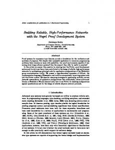
Since UDT uses delay as one of the congestion indications, it is loss free provided that the queue (DropTail) size is large enough for UDT to detect delay. In such a situation, the bandwidth utilization can reach at least 94.4% (= (1+1/ 1.125)/2, supposing that the sending rate changes between 1 and 1/1.125).
10
10
10 RTT (ms)
Figure 3: UDT bandwidth utilization with DropTail queue.
Bandwidth Utilization (%)
Decrease of sending rate can be triggered by either packet loss or packet delay, which are both used as indications of congestion in UDT.
-1
0
-1
10
2
10
1
10
-2
10 0 10 RTT (ms)
Figure 4: Bandwidth utilization and average queue size with RED queue. These 2 conditions are affected mainly by RTT. We use simulation to examine bandwidth utilization under different
Page 5 of 12
Manuscript submitted to Computer Communication Review
RTTs, link capacities, and queue management schemes. The results are shown in Figure 4 and 5. This simulation and all others in this paper were done on NS-2 [34]. In Figure 3, it shows that UDT’s performance increases as bandwidth increases and RTT decreases. Bandwidth utilization is above 98% at most of scenarios, except when the bandwidth is less than 1MB and RTT is greater than 10ms. Figure 4 shows similar trend with RED queue management scheme. The average queue size is also given in Figure 5, which increases as the bandwidth increases. With RED queue management, UDT can reach similar efficiency as that with DropTail queue, but the average queue size is much lower. The performance of UDT also owes to the immediate explicit loss feedback, which can notify loss faster than the 3-duplicate-ACK with timer out mechanism in TCP. It also allows the data sending side to resend only those lost packets. Finally, since UDT uses an increase parameter related to link capacity and a constant increase interval, its convergence time is almost independent of bandwidth and delay.
100ms RTT (below), respectively. DropTail queue is used in this simulation. By using a constant synchronization time instead of an interval based on RTT, UDT almost eliminates the fairness bias by network delay. The impact of RTT will be discussed later in this section (section 4.5). In Figure 6 we demonstrate the RTT independence feature of UDT by using 7 concurrent UDT flows sharing 100Mbps bottleneck link with RTT varying from 1 microsecond to 1 second, but the throughputs only varies between approximately 10 and 20 Mbps. DropTail queue is used in this simulation. Since UDT uses delay to indicate congestion as well as packet loss, when it coexists with TCP (Tohoe, Reno, NewReno, and SACK), TCP will obtain most of the bandwidth unless in high BDP environments where TCP is inefficient. There is one exception: if the link capacity is so small that UDT does not have enough packet samples to detect delay increasing trend before the queue is overflow, the relation between UDT and TCP flows depends on the RTT and queue size. The ratio between UDT and TCP bandwidth shares increases as bandwidth decreases and/or RTT increases. In addition, flow control also plays an important role for TCP friendliness (refer to section 4.3).
4.2 Fairness
For all UDT flows that share only 1 bottleneck link, they will detect the same link capacity. Under such a situation, UDT satisfies the fairness that AIMD satisfies, which has been thoroughly analyzed by [6].
50 Throughput (Mbps)
The rate control mainly decides the throughput of UDT flows since the window size is never less than the product of receiving rate and (RTT + SYN). It actually an AIMD (additive increase multiplicative decrease) algorithm, the increase parameter is related to the end-to-end link capacity and is constant for all flows sharing same bottleneck, and the decrease factor is 1/9 (= 1 – 1/1.125).
20 10
100
100
10 RTT (ms) 1 0.1
9 0
0.01 0.001
8 0 7 0 Throughput (Mbps)
30
0 1000
1 0 0
40
80 60 Time (s)
20 0
6 0 5 0
Figure 6: RTT Independence.
4 0 3 0
The relationship between coexisted UDT and TCP is also related to the synchronization time. Since TCP changes window size every RTT, whereas UDT uses constant SYN time. TCP has advantages over UDT in low RTT link (RTT < 10ms). On the other hand, UDT can probe available bandwidth faster in high RTT link.
2 0 1 0 0
0
1 0
2 0
3 0
4 0
5 0 T im e (s )
6 0
7 0
8 0
9 0
1 0 0
1 0 0 0 9 0 0 8 0 0 Throughput (Mbps)
40
7 0 0 6 0 0 5 0 0 4 0 0 3 0 0 2 0 0 1 0 0 0
0
1 0
2 0
3 0
4 0
5 0 T im e ( s )
6 0
7 0
8 0
9 0
1 0 0
Figure 5: 10 UDT flows share single bottleneck link, with 1 flow added every 5 seconds. Figure 5 demonstrates the fair share among UDT flows. In the simulation, 1 UDT flow is added every 5 seconds. All flows converge to fair share fast and stay at the stable status. The link properties are 100Mbps with 1ms RTT (above) and 1Gbps with
Figure 7 and 8 show the bandwidth share ratio between UDT and TCP under DropTail and RED queue managements, respectively. TCP version is SACK with buffer size set to at least BDP. Queue size in DropTail queue is set to max(2 * BDP, 10), whereas in RED queue it is 20000. When TCP and UDT coexist, the overall bandwidth utilization is similar as that of single UDT flow utilization, showing that UDT can utilize the bandwidth that TCP fails to obtain, but leave enough space for TCP to increase its window.
Page 6 of 12
Manuscript submitted to Computer Communication Review
Figure 9 shows how robust and convergent UDT is in a rapid changing available bandwidth link. In this simulation, a constant bit rate (CBR) UDP flow is set up as background in a 100 Mbps link with 10ms RTT and DropTail queue management. A single UDT flow is used to observe the convergence.
5
3 100 CBR flow rate (Mbps) UDT throughput (Mbps)
Ratio (UDT/TCP)
4
2 1 0
10
-1
10
0 1
1
10 Bandwidth (Mbps) 10 2 10
3
10
-2
10
-1
10
0
10
2
10 RTT (ms)
Figure 7: UDT/TCP share with DropTail queue.
80 60 40 20 0 20 40 60 80 100 0
50
100
6
Ratio (UDT/TCP)
200
250
Figure 9: UDT with rapid changing CBR background flow.
5
We also test UDT in a more complex topology with multiple bottlenecks. The topology and the result are shown in Figure 10. In this figure, the value above the line is the capacity of that link (in Mbps). All RTTs between any 2 adjacent nodes are 10ms.
4 3 2 1
†
0 10
150 Time (s)
100
-1
10
0 1
1
10 Bandwidth (Mbps) 10 2 10
3
10
-2
10
-1
10
0
10
100
10
50
‚
ƒ
„
100
2
10 RTT (ms)
•
Flow ID 1 2 3 4 5 6 Per flow performance (Mbps) with DropTail queue 89.1 5.17 41.7 50.8 4.78 89.2 Per flow performance (Mbps) with RED queue 90.6 90.7 4.54 43.3 50.0 5.16 Figure 10: UDT in multiple bottlenecks topology.
Figure 8: UDT/TCP share with RED queue.
4.3 Stability As is discussed previously, the flow window that limits the number of unacknowledged packets avoids unlimited number of packets to be sent out before the sending side receives any control information indicating congestion. Meanwhile, during high congestion the sender will either reduce the sending rate by 1/9 at least once every RTT or stop to send new packet until the congestion disappears - the sending is frozen for SYN time to clear the congested link. Recall that the interval of loss report for the same packet increase each time, the number of resent packets will not cause congestion collapse. On the other hand, the data sending side will not be blocked with too many control packets. The number of control packets is also limited to avoid congestion collapse from increased control traffic [12]. Meanwhile, UDT does not decrease for any packet loss event to avoid unnecessary drop in sending rate. Continuous sending window decrease is one of the common problems for TCP over long haul link, where large amount of packets have been sent out before the data sending side knows the existence of congestion.
…
4.4 Impact of Estimation Errors In real network environments, the end-to-end link capacity and the delay increasing trend can be misestimated. An underestimated or overestimated link capacity may lead to performance drop. On the other hand, if coexisted flows get different estimated values, unfairness can arise, depending on how the estimated values differ from each other (recall that in (2) only two values are in different scopes of 10’s powers may lead to unfairness). However, since UDT uses its own traffic as probing packets and the probing is across the flow lifetime, this receiver based packet pair method is robust and should converge to a steady status in the long run. The only limitation is that the method will not work well in multi-channel link [15]. Due to end system’s context switch, UDT can also fail to detect the delay increasing (type 1 error), or give a wrong warning but the queue is actually not filling up (type 2 error). Type 1 errors
Page 7 of 12
Manuscript submitted to Computer Communication Review
Type 2 error can only happen occasionally since a stable end system will not continuously cause increase of the RTT estimation in the long run (otherwise the CPU must be using up and the system is no longer proper for running any program). Moreover, UDT does not allow to send more than 1 delay warning in 2*RTT. The frequency of type 1 error may be higher since a small difference in RTTs can be disturbed by the system noise. The probability of type 2 error may depend on specific systems. Nevertheless, even in the worst case that UDT fails to detect all delay increasing trends, the fairness and efficiency will not be affected much. First of all, since UDT only decrease 1/9 for 1 loss event and not every loss events can cause a decrease, it can still reach high performance without delay warning. Second, the intraprotocol fairness will not be affected. Finally, the flow control helps to make UDT less aggressive and friendly to TCP. Figure 11 shows the simulation of UDT/TCP sharing ratio by closing the delay warning mechanism. The simulation uses RED queue.
packets of loss report brings little effect to performance (although it is better to learn congestion as early as possible).
4.7 Impact of Link Error UDT regards all loss as congestion, so it is not proper for links with high link error probability such as wireless networks without any modification. But it still alleviates the TCP problem caused by link error in high BDP environment, since UDT does not reduce its sending rate for any loss report, and it increases in proportional to link capacity and independent of RTT. Figure 12 shows the bandwidth utilization changes of single UDT flow as link error increases. Link capacity has significant effect added to the link error impact, whereas RTT has little effect. 100 B=10Mbps, RTT=100ms B=10Mbps, RTT=10ms B=10Mbps, RTT=1ms B=100Mbps, RTT=100ms B=100Mbps, RTT=10ms B=100Mbps, RTT=1ms
90 80 Bandwidth Utilization (%)
make UDT less TCP friendly, whereas type 2 errors can lead to performance drop.
12
70 60 50 40 30
Ratio (UDT/TCP)
10 20
8
10
6
0 -4 10
4
10
-3
-2
10 Loss Rate
2
-1
10
0
Figure 12: Bandwidth utilization at different link error.
0 10
10
-1 0
10 Bandwidth (Mbps)10 1
1
10
2
10
3
10
-2
10
-1
10
2
4.8 Impact of Queue Size and Management
10 0 10 RTT (ms)
Figure 11: UDT/TCP share with RED queue when UDT delay warning is closed.
Since UDT sends packets at every inter-packet interval, it does not need large queue size to support high throughput. The throughputs are similar under both DropTail and RED queue managements. However, using RED can help to reduce the average queue size, at little cost of performance drop. 100
4.5 Impact of RTT
80 60 10Mbps Link Capacity Bandwidth Utilization (%)
The effect of long RTT to the UDT performance is two folds. On one hand, the loss report or delay warning needs longer time to be fed back to the data sending side in longer RTT link. During this time, the data sending side will continue to send packets at high speed so it is more aggressive. On the other hand, as a consequence of this phenomenon, long-RTT flow intends to suffer more loss or delay and will drop sending rate more frequently than short-RTT link. The former feature dominates the balance and makes UDT favor long-RTT flow slightly. This is convinced in Figure 6.
40 20 0 0
4
6
8
10
12
14
18
20
80 60
RTT = 0.1ms RTT = 0.1ms RTT = 1ms RTT = 1ms RTT = 10ms RTT = 10ms RTT = 100ms RTT = 100ms
40
4.6 Impact of Out-of-Order Packet
16
100
20
Out of order packet is regarded as loss in UDT. If the probability is high, it can substantially affect the performance. A variation of loss detection to receiver’s algorithm is to wait N packets before sending back a loss report, where N is a small number so that most of the out-of-order packet can be corrected. The delay of N
2
0 0 10
1Gbps Link Capacity
10
1
Queue Size
10
2
10
3
Figure 13. Relationship between UDT performance and queue size (DropTail).
Page 8 of 12
Manuscript submitted to Computer Communication Review
In Figure 13 it shows the relationship between UDT performance and queue size. The link capacities are 10Mbps (above) and 1Gbps (below), respectively. In each sub-figure there are 4 curves showing single UDT flow performance with different RTTs from 0.1ms to 100ms. In both scenarios UDT need very small queue size to reach high bandwidth utilization.
In figure 14 it shows that single UDT flow can reach about 940Mbps over 1Gbps link with both 40us short RTT and 110ms long RTT. It can reach about 580Mbps over an OC-12 link with 15.9ms RTT between Canarie and StarLight. 1000
Meanwhile, queue management schemes have little effect on intra-protocol fairness and convergence.
900
4.9 Limitations
700
Another limitation is the intra-protocol fairness in multibottleneck links where the max-min fairness may be violated under some circumstances. This is also caused by the increase parameter, since different flows in multi-bottleneck links may have different end-to-end link capacity. This problem can also be solved if the available bandwidth estimation scheme is presented. Note that the available bandwidth changes from time to time, so the objective here is to find an estimated value that is consistent among all concurrent flows and approximately reflects the available bandwidth for the current piece of time.
5. IMPLEMENTATION RESULTS The UDT protocol and its predecessor SABUL protocol [11, 27] have been implemented on several platforms and used in some real applications. Demonstrations have been shown at conferences such as SuperComputing [18] and IGrid [11].
Throughput (Mbps)
500 400
OC-12, 15.9ms 1Gbps, 110ms 1Gbps, 0.04ms
200 100 0 0
10
20
30
40
50 60 Time (s)
70
80
90
100
Figure 14: UDT performance over real high speed testbeds. We start the 3 flows in Figure 14 at the same time in another experiment to examine the fairness and efficiency of parallel UDT flows. The 3 flows are all sent from StarLight, sharing 1 Gbps bottleneck, and go to Canarie, SARA, and StarLight (local), respectively. The result is shown in Figure 15. 600 Throughput (Mbps)
Although this negative effect can be alleviated by flow control, which presents an upper limit if data sending rate increases too fast, since the window size uses the packet arrival speed resulted from a previous sending rate. It is better to use available bandwidth instead of link capacity in formula (1), which can completely remove this limitation. However, we have not found a practically effective method that can only use the UDT’s own data traffic to estimate available bandwidth.
600
300
400
200
0 0 335 Throughput (Mbps)
Continuous sending rate decreases can happen often if very large amounts of flows share a high capacity link, where the increase can be too large comparing to the per flow throughput. For example, when 10000 flows share 1Gbps link, the average throughput per flow is about 100kbps, but the increase is 1 packet (supposing MTU is 1500 bytes) per SYN time according to formula (2), or 12kbps. This can cause large oscillations, high loss rate and hence performance drops.
800
20
40
60
80
100
60
80
100
to Canarie, 15.9ms to SARA, 110ms to StarLight, 40us
330
325
320 0
20
40 Time (s)
In this section we will explore some results in real networks as a supplement to the simulation in the previous section, since the NS-2 simulation environment does not consider the effects of end system computational abilities and external environments interruptions. Particularly, we want to use these implementation results to examine the impact of computation time to the packet processing and the impact of external disturbances to the calculation of packet arrival speed and delay increasing trend. The experiments are done over 3 high speed network testbeds: StarLight3, SARA4, and Canarie5. 3
http://www.startap.net. Located at Chicago, IL, USA.
4
http://www.netherlight.net. Located at Amsterdam, Holland.
5
http://www.canarie.ca. Located at Ottawa, Ontario, Canada.
Figure 15: Three concurrent UDT flows across different testbeds sharing single 1Gbps bottleneck. As is discussed in the previous section, estimation errors can affect TCP friendliness property. We set up a group of experiments to examine the TCP friendliness in real networks. The TCP version in the experiments is TCP SACK with buffer set to at least BDP. In Figure 16 it shows the result of 2 TCP flows and 2 UDT flows coexisting in StarLight local network, with 1Gbps link capacity and 40us RTT. TCP flows utilize slightly higher bandwidth than UDT flows. A similar experiment is set up between StarLight and SARA, with 1Gbps bandwidth and 110ms RTT. TCP is inefficient in this link. A single TCP flow can only utilize about 20Mbps even the buffer
Page 9 of 12
Manuscript submitted to Computer Communication Review
size is set to 12MB (approximately equal to BDP). Figure 17 shows the 2 parallel TCP flows’ performance with and without 2 concurrent parallel UDT flows. The coexisting UDT flows cause the TCP performance drop to about 1/3. In this figure the I-TCPs are TCP flows without concurrent UDT flows, whereas S-TCPs are with the UDT flows.
Throughput (Mbps)
1000
6. RELATED WORK Earlier idea of protocols using rate based congestion control can be found in NETBLT [24] and VMTP [25]. NETBLT is a bulk data transfer protocol that transfers data block by block. It updates data sending rate after each block according the packet loss of the last data block transfer. NETBLT motivated us to design and implement the early prototype of UDT – the SABUL protocol version 1.0 [27], which uses UDP to transfer data and TCP to transfer control information. VMTP is a message transaction protocol that also uses rate control. However, most recent rate based schemes are motivated by Internet streaming multimedia applications. Such kinds of schemes include TFRC [13], RAP [29], and SCP [16]. The main objective of them is to balance the smoothness requirement of streaming media and TCP friendliness. SCP is similar as UDT in that it employs both rate control and window control.
800 600 400 200
0 TCP-2 100
TCP-1
80
It has been proposed in [7] that window congestion control and rate congestion control can cooperate to form a better mechanism in practical network.
60
UDT-2 UDT-1
40 Time (s)
20 0
Figure 16: TCP and UDT coexist in local high speed network.
TCP Vegas [3] and FAST TCP [14] are protocols that use delay as congestion indication to improve throughput. FAST TCP also sends data packet in a manner of sleeping inter-packet time, or pacing [17], which is a feature to support high performance, like rate based protocols.
Throughput (Mbps)
100
TCP Westwood [5] uses bandwidth estimation to improve TCP performance, especially in lossy environments. Using bandwidth estimation in a transport protocol has also been proposed in [32].
80 60 40 20 100 80
0 S-TCP-2
60 40 Time (s)
S-TCP-1 20
I-TCP-2 I-TCP-1
0
Figure 17: TCP performance over high BDP network with and without concurrent UDT flows. We also set up 500 1MB TCP streams with different number of background UDT flows to examine how UDT can affect short life TCP flows in long haul networks (Between StarLight and SARA, 1Gbps bandwidth, 110ms RTT). The result is shown in Figure 18. Aggregate 500 TCP flows Throughput (Mbps)
120
100
Another related technique is selective acknowledgement, which has been widely used in a lot of protocols, such as NETBLT [24], VMTP [25], XTP [26], and TCP SACK [30]. At the application level, Parallel TCP is a common solution to improve TCP’s performance over high BDP networks, such as PSockets [21] and GridFTP [22]. However, the major difficulty in using parallel TCP is to decide the number of parallelism [23]. A special parallel TCP is HighSpeed TCP [35], which is a variant of TCP and virtually equals to parallel TCP connections. There is a TCP tuning daemon [28] that can help to choose optimal TCP parameters, especially the buffer size and number of parallelism. Using rate based UDP has also been proposed as a scheme for high performance data transfer to overcome TCP’s inefficiency [10]. There are some ongoing work including Tsunami [36], FOBS [38], and RBUDP [37]. These protocols also use TCP to transfer control information.
80
Meanwhile, the problem of bandwidth utilization over high BDP can be better solved at network layer with open loop control, such as ECN [8] and XCP [1], despite of the cost in the possible upgrade of network infrastructure.
60
40
20
0
7. CONCLUSION AND FUTURE WORK 0
1
2 3 4 5 6 7 N u m b e r o f c o e x is t i n g U D T f l o w s
8
9
Figure 18: 500 TCP 1M streams with different number of background UDT flow.
In this paper we presented an application level high performance data transfer protocol. The UDP based protocol combines both rate based and window based congestion to reach efficiency and fairness objectives. The protocol of UDT can utilize the abundant optical bandwidth independent of the link capacity and network
Page 10 of 12
Manuscript submitted to Computer Communication Review
delay. Using constant synchronization time enables the protocol to reach fairness independent of RTT. In addition, it is TCP friendly.
[8] Ramakrishnan, K.K., Floyd, S., and Black, D.: The Addition
The protocol has been implemented on several platforms and released as free software [33]. The application level library needs to be installed only on end hosts with lowest cost. Some data intensive applications have integrated UDT to reach good performance, including streaming join [18], DSTP [31], remote data replication, and high performance FTP. UDT has well satisfied the requirement from high performance computing area, where it is often the case that small numbers of sources share the abundant optical lambdas.
[9] Foster, C. Kesselman, S. Tuecke: The Anatomy of the Grid:
Although UDT is an application level protocol using UDP, the idea can be implemented above other packet switched network layer, e.g., it can use IP directly to become a transport layer protocol.
of Explicit Congestion Notification (ECN) to IP. RFC 3168, Proposed Standard, September 2001. Enabling Scalable Virtual Organizations. International J. Supercomputer Applications, 15(3), 2001.
[10] P. Varaiya, J. Walrand, High-Performance Communication Networks. Morgan Kaufmann, San Francisco, October 1996.
[11] R. L. Grossman, Y. Gu, D. Hanley, X. Hong, D. Lillethun, J. Levera, J. Mambretti, M. Mazzucco, and J. Weinberger, Experimental Studes Using Photonic Data Services at IGrid 2002, FGCS, 2003.
[12] Floyd, S., and Fall, K.: Promoting the Use of End-to-End Congestion Control in the Internet. IEEE/ACM Transactions on Networking, August 1999.
The major limitation of UDT is the calculation of increase parameter, which depends on the end-to-end link capacity estimated by receiver based packet pair. This limitation may make UDT less attractive for links with very large amounts of concurrent flow, such as Internet backbones. It also affects the intra-protocol fairness in multi-bottleneck scenarios.
[13] S. Floyd, M. Handley, J. Padhye, and J. Widmer: Equation-
We believe that by using a practically effective available bandwidth measurement scheme to replace the packet pair scheme, this limitation will be removed. This is our major work to improve UDT in future.
[15] V. Paxson: End-to-End Internet Packet Dynamics.
Based Congestion Control for Unicast Applications. SIGCOMM 2000, Stockholm, Sweden.
[14] F. Paganini, Z. Wang, S. H. Low and J. C. Doyle. A new TCP/AQM for Stable Operation In Fast Networks, Proceedings of IEEE Infocom, San Francisco, April 2003. IEEE/ACM Transactions on Networking, Vol.7, No.3, June 1999, pp. 277-292.
[16] S. Cen, C. Pu, and J. Walpole: Flow and congestion control for Internet streaming applications. In Proceedings Multimedia Computing and Networking 1998.
8. REFERENCES [1] D. Katabi, M. Hardley, and C. Rohrs: Internet Congestion Control for Future High Bandwidth-Delay Product Environments, ACM SIGCOMM 2002, Pittsburg, PA.
[17] A. Aggarwal, S. Savage, and T. Anderson: Understanding the Performance of TCP Pacing. Proc. of IEEE Infocom 2000, pp. 1157-1165.
[2] T. V. Lakshman and U. Madhow: The Performance of TCP/IP for Networks with High Bandwidth-Delay Products and Random Loss. IEEE/ACM Trans. on Networking, vol. 5 no 3, July 1997, pp. 336-350.
[3] L. Brakmo and L. Peterson: TCP Vegas: End-to-End Congestion Avoidance on a Global Internet. IEEE Journal on Selected Areas in Communication, Vol 13, No. 8, October 1995, pp. 1465-1480.
[4] M. Jain and C. Dovrolis: Pathload: A Measurement Tool for End-to-End Available Bandwidth, Proceedings of Passive and Active Measurements (PAM) 2002 workshop, Fort Collins, CO, pp. 14-25.
[18] M. Mazzucco, A. Ananthanarayan, R. Grossman, J. Levera, and G. Bhagavantha Rao: Merging Multiple Data Streams on Common Keys over High Performance Networks, Proc. of SuperComputing 2002.
[19] Y. Zhang, E. Yan, and S. K. Dao: A Measurement of TCP over Long-Delay Network, Proc. of 6th Intl. Conf. on Telecommunication Systems.
[20] W. Feng and P. Tinnakornsrisuphap: The Failure of TCP in High-Performance Computational Grids, Proc. of SuperComputing 2002.
[21] H. Sivakumar, S. Bailey, R. L. Grossman: PSockets: The Case for Application-level Network Striping for Data Intensive Applications using High Speed Wide Area Networks. Proc. of SuperComputing 2000.
[5] M. Gerla, M. Y. Sanadidi, R. Wang, A. Zanella, C. Casetti, and S. Mascolo: TCP Westwood: Congestion Window Control Using Bandwidth Estimation, In Proceedings of IEEE Globecom 2001, Volume: 3, pp 1698-1702.
[22] B. Allcock, J. Bester, J. Bresnahan, A. L. Chervenak, I. Foster, C. Kesselman, S. Meder, V. Nefedova, D. Quesnal, S. Tuecke: Data Management and Transfer in High Performance Computational Grid Environments. Parallel Computing Journal, Vol. 28 (5), May 2002.
[6] D. Chiu and R. Jain: Analysis of the Increase/Decrease Algorithms for Congestion Avoidance in Computer Networks, Journal of Computer Networks and ISDN, Vol. 17, No. 1, June 1989, pp. 1-14.
[7] S. Keshav: A Control-Theoretic Approach to Flow Control,
[23] Hacker, T., Athey, B., and Noble, B.: The End-to-End
Proceedings of ACM SIGCOMM'91, Zurich, Switzerland, September 1991, pp. 3-15.
Page 11 of 12
Performance Effects of Parallel TCP Sockets on a Lossy Wide-Area Network, Proceedings of the 16th IEEECS/ACM International Parallel and Distributed Processing Symposium (IPDPS) 2001.
Manuscript submitted to Computer Communication Review
Data, IEEE Computing in Science and Engineering, July/August, 2002, pp. 44-51.
[24] D. Clark, M. Lambert, and L. Zhang: NETBLT: A high throughput transport protocol, SIGCOMM '87, (Stowe, VT).
[32] M. Allman and V. Paxson: On Estimating End-to-End
[25] D. Cheriton: VMTP: A transport protocol for the next
Network Path Properties. Proc. of ACM SIGCOMM, September 1999, pp. 263-274.
generation of communication systems, SIGCOMM '87, (Stowe, VT)
[26] Strayer, T., Dempsey, B., and Weaver A.: XTP – the Xpress Transfer Protocol. Addison-Wesley Publishing Company, 1992.
[33] UDT source code. http://cvs.sourceforge.net/cgibin/viewcvs.cgi/dataspace/UDT/. [34] NS-2. http://www.isi.edu/nsnam/ns/.
[27] H. Sivakumar, R. L. Grossman, M. Mazzucco, Y. Pan, and Q. Zhang: Simple Available Bandwidth Utilization Library for High-Speed Wide Area Networks, Journal of Supercomputing, to appear.
[35] HighSpeed TCP. http://www.icir.org/floyd/hstcp.html. [36] Tsunami. http://www.anml.iu.edu/anmlresearch.html. [37] E. He, Leigh, J., Yu, O., and DeFanti T. A.: Reliable Blast
[28] T. Dunigan, M. Mathis and B. Tierney: A TCP Tuning
UDP: Predictable High Performance Bulk Data Transfer. IEEE Cluster Computing 2002, Chicago, IL, Sep. 2002.
Daemon, Proc. of IEEE SuperComputing 2002.
[29] R. Rejaie, M. Handely and D. Estrin: RAP: An End-to-end
[38] P. Dickens: FOBS: A Lightweight Communication Protocol for Grid Computing. To Appear on Europar 2003.
Rate-based Congestion Control Mechanism for Realtime Streams in the Internet, Proc. of IEEE Infocom 1999.
[30] Floyd, S., Mahdavi, J., Mathis, M., and Podolsky, M.: An Extension to the Selective Acknowledgement (SACK) Option for TCP. RFC 2883, Proposed Standard, July 2000.
[31] R. Grossman and M. Mazzucco: DataSpace - A Web Infrastructure for the Exploratory Analysis and Mining of
Page 12 of 12