35th International Symposium on Robotics, Paris-Nord Villepinte-France, 23-26 March, 2004
Using Walking Robots for Humanitarian De-mining Tasks P. Gonzalez de Santos, E. Garcia, J. A. Cobano and T. Guardabrazo Industrial Automation Institute – CSIC Crta. Campo Real Km 0.2, La Poveda 28500 Arganda del Rey, Madrid, Spain
[email protected]
human-machine collaboration in the control loop, which is being known as collaborative control. Any potential vehicle, in principle, can carry sensors over an infested field: wheeled, tracked and even legged vehicles can accomplish demining tasks with effectiveness. Wheeled robots are the simplest and cheapest; tracked robots are very good to move in almost all kinds of terrain; but legged robots also exhibit potential interesting advantages for this activity. For instance: • Legged robots only require a finite number of ground contact points decreasing the likelihood of stepping on an antipersonnel mine. • After detecting an antipersonnel mine, the likelihood of going further is higher for a legged robot than for wheeled or tracked rovers. • The inherent omnidirectionality of legged robots is also a great advantage for changing the steering without performing forward/backward manoeuvres. • Legged robots can walk over loose and sandy terrain, and legs endowed with the proper force sensors can identify the stepped terrain to prevent slippage. • A legged robot provides additional motions along the x, y and z components and even body rotations without changing its footprints. The IAI-CSIC legged-robot working team accredits a large experience in the development of walking robots (Gonzalez de Santos et. al. 1995, 2000, 2003, Grieco et al. 1998, Galvez et al. 2000). Since 1999 it has been working in the application of legged robots for detecting and locating unexploded ordnance (UXO) as a very important potential application for this kind of locomotion. Based on this previous experience, the IAICSIC has configured the DYLEMA system based on a legged robot for detection and location of landmines. DYLEMA is a Spanish acronym that means: Efficient Detection and Location of Antipersonnel Landmines. The main aim of this project is to develop a whole system to integrate relevant technologies in the fields of legged locomotion and sensor systems in order to identify the needs of this integration for humanitarian demining activities. This paper presents the on going
Abstract Detection and removal of antipersonnel landmines is an important world-wide concern. A huge number of landmines have been deployed during the last twenty years and demining will take several more decades, assuming the topic that no more mines are going to be deployed in the future. An adequate mine clearance rate requires the use of new technologies such as improved sensors, efficient manipulators and mobile robots. This paper presents some basic ideas about the configuration of a mobile system to detect and locate antipersonnel landmines in an efficient and effective way. This paper describes the main features of the global system that consists of: a sensor head able to detect some kind of landmines; a manipulator to move the sensor head over large areas; a locating system based on a global positioning system, a remote supervisor computer and a legged robot used as a carrier of the referred subsystems. The whole system has been configured to work on a semi-autonomous mode taking care on robot mobility and energy efficiency, as well.
1
Introduction
Detection and removal of antipersonnel landmines is, at the present time, a serious problem of political, economical, environmental and humanitarian dimension. There is a common interest in solving this problem and solutions are being sought in several engineering fields. The finest solution, but maybe not the quickest, is to apply fully automatic system to this relevant task. However, this solution seems to be still very far away from succeeding. Efficient sensors, detectors and positioning systems are, first of all, required to detect, locate and, if possible, identify different mines. Then, adequate vehicles will be of paramount importance to carry these sensors over the infested fields. In this case, arrays of simple sensors or manipulators to scan the terrain using just one simple sensor would be required. During these operations a human operator should be located as far as possible for safety. Fully automation normally produces complex systems and an intermediate and reasonable solution might be teleoperation and
1
results about: the robot configuration, sensor head, scanning manipulator, locators and control system.
2
System description requirements
and
mentioned in section 1. The following requirements are the starting point for configuring the walking robot: • The legged robot will be based on a hexapod configuration. Section 5 justifies this selection. • The legged robot should be lightweight enough to be handled by two grown persons. This requirement is important to rescue the robot from technical o logistics problems. • The robot should be autonomous from the energy point of view. Tethers should be avoided. • The robot should be semi autonomous from the control point of view. Thus, a remote operator should be in the loop to control the system through teleoperation and collaborative control. • The robot is being configured to optimise power consumption, mobility and stability. These are antagonist conditions that are being balanced by a detailed design. Controller. The global control system will be distributed in two main computers: on-board computer and operator station. The on-board computer is in charge of controlling and co-ordinating the manipulator and leg joints, communication with the DGPS and detector as well as communication with the operator station via radio Ethernet. The operator station is a remote computer in charge of defining the main task of the mobile robot and to manage the potential-alarm database. Power Supply. To configure an autonomous robot from the power supply point of view two main solutions are envisaged: A DC power supply using batteries or AC power supply using a fuel generator. In principle, the second solution can provide higher autonomy; however, its heavy weight is an inconvenient. DC batteries provide lower weight, but also less autonomy . Nevertheless, fuel cell technology is growing quickly and promises to be the best option in the near future. Then, the system will be based on DC actuators and systems. Hence, the walking robot is to be configured as a sixlegged-autonomous robot carrying a scanning manipulator, which handle the sensor head. The system will be controlled through teleoperation and collaborative techniques. Following sections give a global view to the system configuration. Section 3 presents the detecting and locating subsystems. Section 4 is focused on the scanning manipulator configuration. The walking robot is sketched in section 5. Section 6 introduces the controller and, finally, section 7 presents some preliminary conclusions.
main
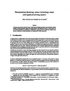
The DYLEMA project, as mentioned above, is thought around a walking robot to detect and locate antipersonnel landmines. For this purpose the overall system is broken down in the following subsystems illustrated in Figure 1: Sensor head. This subsystem contains the mine detector and additional elements to detect the ground and objects in the way. The sensor head is configured to detect potential alarms, but also to allow the controller to maintain the sensor head at a given height over the ground by using simple range sensors. Touch sensors are also provided to detect objects in the sensor head trajectory. Scanning manipulator. The sensor head is basically a local sensor. That means it is able to sense just a point. The efficiency of such a device can be improved by moving the sensor head through a large area. The simple way is by using a manipulator. Therefore, DYLEMA project uses a manipulator to move the sensor head and to adapt the sensor head to terrain irregularities. Section 4 justifies the use of a 5DOF manipulator for this purpose. Dimensions of the scanning manipulator depend on the dimension of the walking robot (leg spread and body height). Locator . After detecting a suspect object the system has to mark the exact location in a database for a posterior analysis and deactivation. We consider that an accuracy of about ±2 centimetres is adequate for locating landmines. This accuracy can be obtained with commercial systems such as DGPS (Differential Global Positioning Systems). Mobile robot. A mobile platform to carry the different subsystems across the infected field is of vital importance to de-mine entire fields. In our case, the platform is based on a legged robot for the advantages Radio Ethernet aerial DGPS Walking robot Operator station
Onboard computer Power supply
3
Scanner (manipulator)
Detection and location of landmines
This section describes two DYLEMA subsystems based on commercial devices: sensor head and locator. The sensor head is based on a commercial mine detector set. However, the whole sensor head consists in an
Detector Figure 1. DYLEMA Global system
2
innovative system integrating several range and touch sensors. Section 3.1 describes and justifies the sensor head design. The locator itself is a commercial DGPS system. Features are commented briefly in section 3.2 and a small justification of its selection is provided.
very small metallic objects, typically mines with a very small proportion of metal content. The full sensor head and the manipulator are shown in Figure 2. This sensor head consists of a support containing the metal detector plus additional range sensors (infrared sensors) to detect the ground and control both sensor-head height and attitude. These sensors are located in pairs defining the higher and lower limits of the band in which the sensor head works. This allows the controller to adapt the sensor head to terrain irregularities. A bumper based on switches with a flexible band is located around the sensor head as a shock absorber. This bumper reports to the controller the position of objects in the sensor head trajectory. This allows the controller to go around obstacle.
3.1 Sensor head There are different sensor technologies for detecting mines. The simplest one consists in a metal detector device. These sensors are simple, lightweight and easy of use. However, they only detect mines with some metallic parts and become inefficient with non-metallic mines (plastic mines). In such a case, other type of sensor such as those based on Ground Penetrating Radar (GPR) (Gader et al. 2000), chemical sensors (Albert et al. 1999) or artificial noses (Rouhi 1997) must be used. It is commonly accepted that an efficient detection system should merge different technologies altogether. Nevertheless, DYLEMA project is devoted with the development of mobile robotics techniques for identification and location of landmines. No sensor development is under the scope of the project. Therefore, a metal detector seems to be the simplest selection for a demining sensor, just to help in the detection and location of potential alarms . After detection of a suspect object, its location must be marked in the system database for further analysis and possible deactivation. For DYLEMA project purposes the commercial mine detecting set Schiebel AN-19/2 is used. This detector is in service in the US Army as well as in several NATO countries. It has been designed to detect
3.2 Locator Marking the position of any suspect object is mandatory in demining tasks. In an automated or semiautomated system a computer database seems to be the most efficient manner for keeping a record of alarms . But, first of all, it is necessary to locate accurately the potential alarms . GPS technique is a good candidate: simple to use and accurate enough. However, GPS technology exhibits some lacks: it is extremely expensive, prone to malfunctions in areas covered with natural objects (trees, large rocks, etc) and requires additional equipment (one more antenna) for getting accuracy. Thus, we have planned to study alternative solutions such as co-operating robots. Nevertheless, a DGPS system is going to be considered as the first solution. Then, this system will be used for calibration of oncoming new systems . DYLEMA project requirements state locating alarms with an accuracy of about ±2 centimetres. This accuracy can be accomplished with the Real Time Kinematics (RTK) technique. However, it requires an additional GPS antenna that will be placed at the operator station (see Figure 1). With these preliminary specifications the DGPS 5700, manufactured by TRIMBLE, seems to be an adequate candidate for our application.
Attachment to robot’s body Shoulder joint
Infra-red sensor
4
Elbow joint
Scanning manipulator
DYLEMA project will use a sensor head based on a metal detector, which is a device that senses just a point or very small areas. Thus, it is necessary a scanning device able to carry the sensor across big areas. The easiest system could be a manipulator developed on purpose. This manipulator requires 3 DOF for positioning the sensor in a 3D area: assuming that the system is scanning a non-flat area, motions in the x, y and z components are required. Also, it would be necessary to adapt the detector to small terrain inclinations; hence, two additional DOF to control detector attitude are needed in the wrist. The detector has radial symmetry, therefore it is not necessary any additional DOF for orientation control. Summarising,
Bumper Metal detector Figure 2. Scanning manipulator and sensor head
3
we got that it is required, at least, a 5-DOF manipulator to accomplish with the task. The manipulator is designed to carry the sensor head; therefore, the design is optimized for carrying just this load. First, the load is balanced to move the detector ±45º in its pitch and roll wrist axes with the lower torque. This is accomplished by placing the detector in a configuration in which no torque is required in the normal position (detector levelled at rest). Regarding the manipulator, a RRR arm configuration is good enough for this application. Mobility is adequate and, being the links in a vertical plane, collisions with the environment decrease (assuming the robot’s body is levelled). One more design clue is to locate the joint motors in the required position to balance the loads and decrease required torques . Figure 2 shows a detailed design of the scanning manipulator taking into account the aforementioned design requirements.
5
one leg design has many advantages in reference with design cost, replacements, modularity and so on. A satisfactory force distribution and homogenisation of the system can be accomplished by displacing the central leg a little bit from the longitudinal body axis . In this case the central legs support a lower weight and the corner legs increase their contribution in supporting the body. This effect is illustrated in Figure 3, which represents a legged robot supported on three legs. The equilibrium equations that balance forces and moments are given by (Klein 1990):
x1 y 1 1
x5 y5 1
x4 F1 0 y4 F5 = 0 1 F4 W
(0)
The condition for sharing homogeneously the weight of the robot among the supporting legs is:
X Y 1
Walking robot configuration
Walking robots are intrinsically slow machines and it is well known that, from the theoretical point of view, machine speed depends on the number of legs (Waldron et al. 1984). Therefore, a hexapod can achieve higher speed than a quadruped and a hexapod achieves its higher speed when using a wave gait with a duty factor β = 1/2, that is, using alternating tripods (Song and Waldron 1989). Although stability in not optimum when using alternating tripods, a hexapod configuration has been chosen just to try to increase the machine’s speed. The walking robot development is based on some subsystems developed for the SILO4 walking robot. This is a quadruped robot developed for basic research activities and educational purposes (Gonzalez de Santos et al. 2003). For this reason, this new walking robot is named SILO6, referring its six legs.
−X
0 W / 3 0 −Y4 W / 3 = 0 1 W / 3 W
Y 1
(2)
Rows 1 and 3 are always satisfied and row 2 is satisfied if: 2Y = Y4 (3) This last condition produces an unusual configuration that looks not very adequate for our application. In any case, the further the central foot is from the longitudinal body axis the more homogeneous force distribution results. The adopted solution has been to choose equal legs and locate the central legs in an advanced position with reference to the longitudinal body axis . The final leg location has been a compromise between body shape and leg positions. 5.2 Leg structure Walking robots need leg configurations that provide just contact points with the ground. Therefore, a 3-DOF device is enough to accomplish motion. Legs have to be
5.1 Body structure The body of a walking robot has the main tasks of supporting legs and accommodating subsystems . Therefore, is must be big enough to contain the required subsystems: on-board computer, electronics, drivers, DGPS, batteries, etc. Preliminary volumes of these subsystems define the volume of the body. Alternating tripods means that two non-adjacent legs of one side and the central leg of the opposite side alternate the support of the robot. That means that for a given position of feet the central leg in support phase is carrying about half the robot’s weight, while the two collateral legs in support phase are carrying about one fourth of the robot’s weight. This is especially significant in traditional hexapod configurations in which legs are placed at the same distance from the longitudinal axis of the body. If the robot has similar legs, then the non-central legs will be over dimensioned and to optimise the mechanism the central leg design should differ from the rest of legs. However, using just
Body Leg
(-X,Y)
(X,Y) F5
(0,-Y4 )
F1
F4 Figure 3. Force distribution for a tripod configuration
4
designed to be lightweight mechanisms and have to support the robot's weight. Therefore, the load carried by each leg is very high and can be supported with the leg in different configurations. A mammal configuration is the most efficient leg configuration from the energy point of view (lower torques are demanded). However, it is not very efficient if we analyse stability. Insect-like legs seem to be more efficient in this case; nevertheless, power consumption increase extraordinarily with this configuration. The idea is to provide a leg configuration able to accomplish with both stability and energy efficiency (very important in outdoor mobile robots); therefore, a leg able to get mammal and insect configuration is being developed. The starting point is to consider the torques the robot has to provide in an insect configuration (the worst case). It is quite evident that joint 2 must support the highest torque. An adequate way of decreasing motor size is by using actuators in parallel; that is, actuators are placed in such a way that two actuators work at the same time to accomplish motion in just one joint. Simultaneous motions in two joints are also allowed. This configuration gives the benefit of using small motors. Therefore, a differential driving mechanism will be used for joint 2 and 3. Figure 4 shows a preliminary design of the leg. Feet can be designed in two basic configurations: a ball fixed to the ankle or a flat sole with some articulated passive joints. The first one is the simplest and can be adequate for applications in loose terrain if the radius of the ball is big enough.
6
them are based on PC-based computers (see Figure 1). The operator station will run under Windows XP operating system and the on-board controller (robot's controller) will run under QNX, a UNIX-like real-time multitasking operating system. Communication between operator station and on-board computer will be performed by radio Ethernet. The operator station is based on a PC bus computer remotely located from the walking robot and is in charge of the robot/user communication. It consists of the following modules: 6.1.1 Man-Machine Interface This module is a Java-based program intended to accomplish three main requirements: (a) robot state monitoring, (b) robot teleoperation and (c) task definition. The user will have the ability to remotely govern the robot motion, having real-time visual information of what the robot is doing. The manmachine interface also allows the user to define the task. This implies the definition of mine-field features (field dimensions, roughness, etc), robot path and autonomous navigation strategies. Figure 5 shows how the manmachine interface looks like. 6.1.2 Alarm Database Manager Each time the robot detects an alarm the spatial position of the detection is stored in a relational database. The user is allowed to find every alarm location found in a given field of a given country. Field and mine features are also stored. This database enables the subsequent mine removing task.
Control system
6.1.3
The control system is distributed between the operator station and the on-board controller. Both of
Mobile robot communication
Communication between the operator computer and the on-board computer is achieved by means of a radio Ethernet card. The operator computer runs under Windows XP operating system, while the on-board controller runs under QNX operating system. The
Motor 1 Motors 2 and 3 Differential system
Joint 3 Joint 1
Joint 2
Body
Foot Figure 4. SILO6 leg configuration
Figure 5. Man-Machine Interface
5
different operating systems used require the election of a communication protocol compatible with any operating system. Such protocol is the TCP/IP (Transmission Control Protocol/Internet Protocol) used world-wide for internet connection. A client-server architecture has been chosen for inter process communication, where the operator computer is the server and the on-board computer is the client. The on-board controller is a distributed hierarchical system composed of a PC-based computer, a dataacquisition board and eight three-axis control boards based on the LM629 microcontrollers, interconnected through an ISA bus. The LM629 microcontrollers include digital PID filters provided with a trajectory generator used to execute closed-loop control for position and velocity in each joint. Every microcontroller commands a DC motor-joint driver based on the PWM technique. An analogue dataacquisition board is used to acquire sensorial data from the different external equipment (sensors, locators, etc.). A radio Ethernet card is provided for network communication with the operator station. Additional electronic cards for interfacing the detector are also provided as well as communication with the DGPS systems via RS232.
7
Acknowledgement This work has been funded by the Spanish Ministry of Science and Technology under Grant CICYT DPI2001-1595.
References Albert, K.J., Myrick, M.L., Brown, S.B., Milanovich, F.P., Walt, and D.R., 1999, High-Speed Fluorescence Detection of Explosives Vapor", SPIE, 3710, pp. 308-314. Gader, P. D., Nelson, B., Frigui, H., Vaillette, G., and Keller, J., 2000, Landmine Detection in Ground Penetrating Radar using Fuzzy Logic, Signal Processing, Special Issue on Fuzzy Logic in Signal Processing (Invited Paper) , Vol. 80, No. 6, pp. 10691084. Galvez, J.A., Estremera, J. and Gonzalez de Santos, P., 2000, SILO4: a versatile quadruped robot for research in force distribution, Proceedings of the 3 rd International Conference on Climbing and Walking Robots and the Support Technologies for Mobile Machines, Professional Engineering Publisher, U.K., pp. 371-383. Gonzalez de Santos, P. and Jimenez, M.A., 1995, Generation of discontinuous gaits for quadruped walking machines, Journal of Robotics Systems, Vol. 12, No. 9, pp. 599-611. Gonzalez de Santos, P., Armada, M.A. and Jimenez, M.A, 2000, Ship building with ROWER, IEEE Robotics and Automation Magazine, Vol. 7, No. 4, pp. 35-43. Gonzalez de Santos, P., Galvez, J.A., Estremera, J. and Garcia, E., 2003, Towards the use of common systems in walking machine research, IEEE Robotics and Automation Magazine, In Press. Grieco, J.C., Prieto, M., Armada, M.A. and Gonzalez de Santos, P., 1998, A six-legged climbing robot for high payloads, Proceedings of the IEEE International Conference on Control Applications, Trieste, Italy, pp. 446-450. Klein, C.A.; Kittivatcharapong, S., 1990, Optimal force dDistribution for the legs of a walking machine with friction cone constraints, IEEE Transactions on Robotics and Automation, Vol. 6, No. 1, pp. 73-85. Rouhi A.M., 1997, Land Mines: Horrors begging for solutions, chemical & Engineering news, Vol. 75, No. 10, pp. 14-22. Song, S.M. and Waldron, K.J, 1989, MACHINES THAT WALK: The Adaptive Suspension Vehicle. The MIT Press Series in AI. Waldron, K.J., Vohnout, V.J., Perry, A., and McGhee, R.B., 1984, Configuration design of the adaptive suspension vehicle, The international Journal of Robotic Research, Vol. 3, No. 2, pp.37-48.
Conclusions
Detection and location of antipersonnel landmines is being mainly carried out by a human operator handling manual equipment. Robotization of this activity can give so many benefits to the human community in many countries. There is a world-wide interest in eradicating laid landmines and solutions are coming from new emerging engineering fields. New sensors are being required to detect landmines efficiently, but current sensors can be carried by mobile robots . Legged locomotion provides some important advantages for moving in natural terrain and seems a good solution to carry mine sensors over infested fields in an efficient way. Some preliminary work has been developed in studying the potential possibilities of using walking robot for demining. This paper addresses the development of a walking robot endowed with a manipulator able to scan areas with a sensor head based on a metal detector. The potential advantages of walking robots and a new system for landmine detection are also presented. This paper introduces the main system and some details of the walking robot and manipulator configurations are provided. The system has to be completed with the required tools to form databases of the potential alarms as well as providing adequate images and graphs to the operator. The incorporation of new sensors, detectors, and software for signature analysis will be provided in a second project step.
6