Using Web-based laboratories for control engineering education Sebastián Dormido1, Héctor Vargas2, José Sánchez 3, Natividad Duro4, Raquel Dormido5, Sebastián DormidoCanto6, Francisco Esquembre7 Abstract - This paper describes the experience of the Department of Computer Sciences and Automatic Control of the Spanish University of Distance Learning (UNED) about the use of Web-based laboratories in a distance course on automatic control. To begin with, we present the approach followed to transform three conventional didactical setups (a three-tank system, a heat-flow apparatus and an electrical drive servo motor) into virtual/ remote control laboratories. This approach differentiates two layers in the construction of Webbased laboratories: the experimentation layer and the elearning layer. For the experimentation layer, LabVIEW and data acquisition boards from National Instruments are used to create the server-side applications, and Easy Java Simulations for the client-side interfaces. For the elearning layer, the eMersion environment is used to support the required flexible educational scheme. Index Terms - Remote laboratory, Distance learning, Control engineering education, Interactive systems, Web-based experimentation, Collaborative learning. INTRODUCTION Technological advances in communication networks are steadily being introduced to improve both the quality of service and the available bandwidth of Internet to accommodate the increasing world-wide demand of resources. The availability and capabilities of these new communication facilities, combined with the fast development of Web technologies and the generalization of off-the-self components for data acquisition and control of industrial processes, now enable students to avoid attendance to traditional laboratories. Students are encouraged to use tele-presence systems, transforming the remote experimentation from a subject of research into a reality accessible to everybody. Control Engineering is one of the technical areas in which the impact of new technologies to develop novel approaches to distance learning is most noticeable [1]. A great number of research groups, universities, and academic institutions all over the world are currently implementing virtual and remote control laboratories with one objective in common: to enhance traditional teaching
processes by taking advantage of modern technologies However, it would be very convenient for the control education community to establish a common approach to describe, implement, and link each of the parts that compose a Web-based laboratory. This approach should include a Web-based experimentation platform that supports both the student-teacher interaction and the collaborative processes among students in a way similar to how it takes place in the traditional classroom. This paper presents the approach currently used at UNED about how to create virtual and remote control laboratories. The paper is organized as follows. Section 2 describes the experimentation layer, which includes the fundamental aspects required to create virtual and remote control laboratories using LabVIEW and Easy Java Simulations. Section 3 presents the eMersion-based e-learning layer, which implements the complementary Web-resources that users need to make a correct use of the experimental application. Section 4 lists all the steps needed to develop a virtual and remote control laboratory completely integrated in eMersion by using a servo-motor as didactical setup. Section 5 provides two additional examples of remote experiments developed by the authors. Finally, some conclusions and considerations about further work are given. EXPERIMENTATION LAYER Excluding some specific efforts [2],[3], there is no unified methodology or procedure to design, develop, and publish virtual and remote laboratories on the Internet. However, analysing the growing number of publications (journals and conference proceedings) related to Web-based laboratories, it is possible to distinguish a set of basic features that are frequently used as methodological steps for designing an integral environment for remote, pedagogical-oriented experimentation. The first feature corresponds to the design of an experimentation layer. This layer includes the creation of the interactive client-side interfaces and the server-side applications that run the real-time control loop and the transmission components for exchanging information with the remote user interface. The second main feature is the design of an e-learning layer necessary to deploy the Webbased resources over the Internet.
1
Department of Computer Sciences and Automatic Control, UNED, C/. Juan del Rosal 16, 28040 Madrid (Spain),
[email protected] Department of Computer Sciences and Automatic Control, UNED, C/. Juan del Rosal 16, 28040 Madrid (Spain),
[email protected] 3 Department of Computer Sciences and Automatic Control, UNED, C/. Juan del Rosal 16, 28040 Madrid (Spain),
[email protected] 4 Department of Computer Sciences and Automatic Control, UNED, C/. Juan del Rosal 16, 28040 Madrid (Spain),
[email protected] 5 Department of Computer Sciences and Automatic Control, UNED, C/. Juan del Rosal 16, 28040 Madrid (Spain),
[email protected] 6 Department of Computer Sciences and Automatic Control, UNED, C/. Juan del Rosal 16, 28040 Madrid (Spain),
[email protected] 7 Department of Mathematics, University of Murcia, Campus de Espinardo, 30100 Murcia (Spain),
[email protected] 2
Coimbra, Portugal
September 3 – 7, 2007 International Conference on Engineering Education – ICEE 2007
In our approach, the experimentation layer has been developed following the usual client-server architecture. To illustrate the experimentation layer, the next two subsections describe some design considerations and programming techniques.
instrument (VI), and these threads can run at different sampling periods and with different priorities.
I. Building the Server-Side Figure 1 shows the standard structure of a feedback loop in control systems theory. The operations performed in a feedback loop follow a standard sequence and the sequence of operations is known as the control task that must be carried out at a fixed time-interval called the sampling period that is chosen in accordance with the dynamics of the physical process. This fixed sampling interval or cycle time defines implementation constraints when using traditional control analysis and design techniques where a constant sampling period is often assumed [4]. The notion of real-time control is based on the above implementation constraints where the computer operations rely on a deterministic time occurrence. The implementation of this type of applications in control engineering education and, especially, in virtual and remote experimentation across the Internet is commonly made using LabVIEW software [5], [6].
FIGURE 2 GENERAL ARCHITECTURE TO DISTRIBUTED CONTROL APPLICATIONS USING LABVIEW AND EJS
III. Building the client-side interfaces Easy Java Simulations (EJS) [7] has been chosen to develop the client interfaces. EJS is a free software tool designed to create scientific simulations in Java, which is being used successfully to develop virtual and remote control laboratories [8]-[13]. Simulations in EJS are structured in two parts: the model and the view (see Fig. 3). The model describes the behaviour of the system using variables, ordinary differential equations, and Java code. The view provides the visual and graphical aspects of the simulation. Both parts are closely interconnected since the evolution of the model state affects the view and the interaction of the user with the view affects the model.
FIGURE 1 FEEDBACK CONTROL SCHEME
II. Using LabVIEW for remote experimentation Because of the hard constraints in its sampling period, the execution of the control task must take place as regularly as possible. Using LabVIEW, such regularity is achieved by using threads and DAQ board interrupts. However, to run a local version of the control task through the Internet, some modifications are required. In particular, it is necessary to add the LabVIEW code that handles the communication with the remote client and with the video camera that provides the adequate visual feedback of the behaviour of the plant in the laboratory. Figure 2 shows a general scheme of this idea. The three boxes on the server-side represent each of the tasks required. Since the control task must keep the constraints in the cycle time, it is necessary to ensure its determinism in the execution by assigning to it the highest priority. The communication and video tasks are run in parallel to the control task on different threads with lower execution priorities. Finally, it is also necessary to perform the methods that share data among tasks respecting the determinism of the control task. LabVIEW shows very adequate here, since it provides simple multi-thread programming. Since LabVIEW 7.1, authors can program multiple threads in a single virtual
FIGURE 3 STRUCTURE OF A CLIENT-SIDE APPLICATION IN EJS.
Creating an application with EJS requires only a minimum knowledge of Java. EJS provides extensive scaffolding to create the model of the system by defining the variables that describe the system state and specifying the constitutive equations that govern how this state changes with time. In addition EJS includes a library of ready-to-use graphical elements that can be used to build sophisticated and
Coimbra, Portugal
September 3 – 7, 2007 International Conference on Engineering Education – ICEE 2007
interactive views by simple drag and drop (See View panel in Fig. 4). The graphical properties of the elements used in the view can be linked to the model variables, producing a bi-directional flow of information between view and model: any change of a model variable is automatically displayed in the view, and, reciprocally, any user interaction with the view produces an automatic modification of the value of the corresponding model variable. Once the developer has defined the model of the process (including the Java code to exchange information with the server-side in remote mode) and the view of the interactive user interface, EJS generates the complete Java source code, compiles it, packages the resulting object files into a compressed file, and generates HTML pages containing the narrative and the applet. The user can then directly run the applet and/or publish it over the Internet. The servo-motor example of Section 4 illustrates all the stages required for the creation of a client-side application using EJS. Complete information about Easy Java Simulation can be freely downloaded from http://www.um.es/fem/EJS/. USING EMERSION
AS THE E-LEARNING LAYER
This section describes eMersion, a collaborative environment developed at the Ecole Polytechnique Fédérale of Lausanne (EPFL) [14]. From a pedagogical perspective, eMersion is a very convenient environment for distance learning in engineering because it incorporates all the elements needed to complete experimental sessions emulating the work carried out in the traditional lab [15]. I. The eMersion environment The Department of Computer Sciences and Automatic Control at UNED is using the eMersion to support the experiments carried out by its control engineering students across Internet.
called fragments. The experimentation console module contains the Java applet developed with EJS. Using it, students can perform their laboratory assignments by accessing to the real laboratory resources through a local network (remote laboratory) or by simulating the process using a mathematical model (virtual laboratory). The on-line documentation module provides a portfolio with theory, assignments, task protocols plus the additional information needed to complete an experiment. The protocol describes the tasks to be performed during the laboratory session. These tasks are of two kinds: prelabs and labs. The first ones are assignments to carry out in simulation mode to gain knowledge about the real process. Only when the prelabs are mastered, will students obtain remote access to the plant located in the laboratory. Through the navigation bar the user can access the different modules described above. II. Integrating EJS applications in eMersion EJS offers several predefined Java built-in methods to ease the integration of client-side applications in eMersion. These methods allow EJS applications to exchange fragments of data and snapshots of the graphical scopes with the e-Journal. Figure 5 shows a part of the structure of the EJS view corresponding to the servo motor application discussed in the next section. The left part on the main window displays the tree-like structure of view elements that make the graphical interface. The right-hand side of this window contains the individual graphical elements that EJS offers to developers to elaborate the views: graphical containers, panels, buttons, text-fields, labels, menus, 2D and 3D drawing elements, control symbols, etc. These elements are selected by dragging and dropping them to the view tree. The Figure shows three auxiliary windows with the Java code executed when the user selects the menu options labeled SaveGraph, StartRecord, and StopRecord. This Java code uses some EJS built-methods that send information to eMersion.
FIGURE 4 COMPONENTS OF THE E-LEARNING LAYER FOR REMOTE EXPERIMENTATION
Figure 4 shows the functional structure of the collaborative environment. The system is composed of four parts: the eJournal, the experimentation console, the on-line documentation, and the navigation bar. The eJournal module provides a shared space to facilitate the communication and collaboration among students and instructors during the learning process. In this shared space students can store, retrieve, and exchange their experimental results and documents. Documents and files stored in the eJournal are
FIGURE 5 INTEGRATION OF EJS APPLICATIONS IN THE EMERSION ENVIRONMENT
All the data files produced with these predefined methods are automatically stored in the e-Journal, so the EJS
Coimbra, Portugal
September 3 – 7, 2007 International Conference on Engineering Education – ICEE 2007
developers do not need to include extra Java code to exchange information between both environments. A SERVO MOTOR PROTOTYPE As an illustration of these ideas, a brief description of the development of a virtual and remote control laboratory of an electrical drive servo motor (eElab for short) is presented in this section. The eELab equipment is located in the laboratory of the Department of Computer Sciences and Automatic Control at UNED. The prototype is part of a set of didactical setups specially selected to be used in remote experimentation environments. Other prototypes available are a three-tank system and a heat-flow apparatus. Currently all these prototypes can be manipulated via Internet by accessing on-line courses on control engineering available in the eMersion environment. I. The server-side application for the eElab
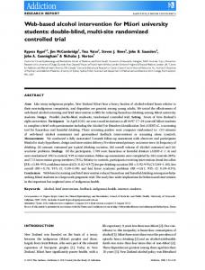
II. The client-side of the eElab Figure 6 presents the client-side interface (experimentation console) developed in EJS to operate in virtual mode (using a model of the motor) or in remote mode with the eELab. The window is divided into two parts. The left part contains an image of the motor and a control panel used to define different system parameters. The virtual representation has been developed copying the frontal view of the real motor. Hence, any variation of the system state during the simulation mode will be displayed as a rotational movement of the disk. However when the user works in remote mode, this virtual representation will be replaced by the video images sent from the server. When the application is working in remote mode, the Augmented option can be enabled. In this configuration a virtual representation of the motor is overlaid on top of the video image. When the available bandwidth is not large enough, the virtual representation can serve as a substitute of the video stream.
Table 1 contains a summary of the technical features of the hardware and software elements used to develop the eELab server application. TABLE 1 HARDWARE AND SOFTWARE TO DEVELOP THE EELAB SERVER SIDE eElab servo motor The eElab [16] is composed by a DC motor that drives a steel disk that acts as a load. Either the angular position or the speed can be controlled by adjusting the DC voltage. The eElab is equipped with a firewire video camera that films the rotating disk. Server computer Intel® Pentium® 4. 1 GB RAM. 3 GHz CPU. Windows 2000/XP Professional, SP 2. PCI-E Gigabit Ethernet Controller. Acquisition device A NI PCI-6025E board is used to connect the server computer and the eELab. The board has 12 bits resolution and a maximum sampling rate of 200 kHz. It has 16 analogue input channels, 2 analogue output channels and 8 digital input/output channels. Software LabVIEW 7.1 with NI-DAQ 7.4 drivers to interface with the NI PCI6025E card. The QTLIB 2583 LV70.llb library is used to communicate the LabVIEW application and the camera of the eELab.
Considering the time constant of the motor (0.253 sec), a sampling period of 20 ms was chosen to satisfy the sampling theorem. To guarantee the sampling period accuracy in the control task, a timer found in the DAQ board is used. This timer conveniently permits to synchronize the AD and the DA conversion. The control algorithm is a standard PID controller with set-point weighting, anti-windup mechanism, and filtering of the derivative action [4]. Within the video task, images are acquired using the builtin firewire camera. These images are read, compressed in JPEG format, and passed-on to the communication task at 10 frames per second, a value that provides the distant user with an acceptable visual feedback of the real process. These images are then decompressed and rendered within the client EJS application. The communication task performs the data exchange between the client and the server.
FIGURE 6 THE EELAB INTEGRATED IN THE EMERSION ENVIRONMENT
The control panel contains two subpanels accessible by tabs. The first tab, named Control (visible in Fig. 5), lets the user choose the type of experience (virtual or remote), switch between position or speed control, and change the system dynamics (for instance, modifying the set point or introducing disturbances by varying the brake). The four buttons located at the bottom of the control panel (Play, Pause, Reset, and Connect) allow specifying how the system must work. The Connect button starts the remote mode by connecting to the real process running at the university laboratory. By default, the application begins working in simulation mode. The second tab presents sliders and buttons to tune the PID controller. Finally, a status bar below the control panel displays messages related to the state of the connection between client- and server-sides. The right part of the main window contains two mixedsignal scopes and numerical fields that show the evolution of the process variables. The status bar located at the bottom indicates the time remaining for the remote session. In the upper part there are three menus labeled eJournal, Control, and Language. The eJournal menu provides commands to
Coimbra, Portugal
September 3 – 7, 2007 International Conference on Engineering Education – ICEE 2007
take a snapshot of the evolution of the system in GIF format and to save a record of the value of its variables in plain text format. The Control menu allows switching between manual (the voltage applied to the motor is driven by the user) and automatic control mode (the voltage to the motor is calculated automatically by the PID controller). III. The eELab control laboratory integrated in eMersion Figure 6 shows the general view of the eELab remote laboratory integrated in eMersion. The upper frame displays the navigation window, which allows users to access the different modules of the experimentation environment. The Objective area contains a textual description of the topic covered in the laboratory. The Navigation area contains a group of icons that grant users access to the different modules described in Section 3. The window on the right contains the eJournal. Data fragments produced from the user interface will automatically be stored in the eJournal. These fragments can later be used by students to generate reports.
console when running in virtual mode. To reduce the student learning curve the experimentation consoles in the proposed Web-based laboratories are always very similar. In the case of the heat-flow console, at the top of the window there is a 3D representation of the setup whose color varies according to the air temperature inside the duct. It can be considered as a kind of augmented reality technique to reinforce to the user the feeling of physical presence. At the bottom of the left panel, there are control elements that allows the user to choose the type of experience (virtual or remote), switch the control mode (open or closed loop), and a set of sliders and buttons to change the operating conditions (for instance, changing the set point or introducing some disturbance by varying the heater voltage Vh).
OTHER EXAMPLES OF REMOTE EXPERIMENTATION This section describes two other applications developed using the design considerations described in this paper. These Web-based applications have been developed to present specific PID control concepts, as the temperature control of a heat-flow system, and level control for a set of interactive tanks. These two laboratory experiments provides the same capabilities as the eELab and can both be remotely controlled or used in simulation mode. FIGURE 8 INTERFACE DEVELOPED WITH ELEMENTS OF THE EJS GRAPHICAL LIBRARY
FIGURE 7 THE HEAT-FLOW SETUP BY QUANSER
Figure 9 shows the experimentation console when users work with the didactical setup instead of with the heat-flow simulation. In this case, the 3D view of the heat-flow is replaced for a real-time video image of the apparatus. Since the air heating process can not be appreciated in the image, users can choose to overlap the video and the virtual 3D visualization in order to appreciate the change in air temperature.
I. The heat-flow web-based laboratory The temperature control system (Heat-Flow) has been developed by Quanser Consulting (Figure 7) [17]. This system presents features to study concepts of temperature flow control system with transport lag and identification techniques. The setup consists of a duct with the following components: a heating element and a blower located at both ends of the structure, and three temperature sensors S1, S2 and S3 along the duct. The power delivered to the heater and the fan speed can be controlled using the analogue signals Vh and Vb. Fan speed is measured using a tachometer that produces an analogue signal Vt which can be used to design speed controllers. A model was required to build the virtual laboratory simulation. Figure 8 shows the main window of the experimentation
FIGURE 9 EXPERIMENTATION CONSOLE WHEN THE REAL DIDACTICAL SETUP IS USED FOR EXPERIMENTATION INSTEAD OF THE MODEL
Coimbra, Portugal
September 3 – 7, 2007 International Conference on Engineering Education – ICEE 2007
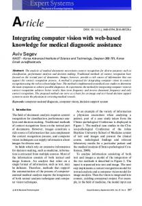
II. The three-tank laboratory The three-tank setup has been proposed as a benchmark system for different purposes, for instance, test system for fault detection, identification and multivariable control, and reconfigurable control. To develop this laboratory, the DTS200 three-tank system manufactured by Amira GmbH [18] was selected (Figure 10).
three tools: Easy Java Simulations, LabVIEW and eMersion. The proposed component approach eases the development of online experimentation environments. It also provides an effective scheme to switch between simulation and actual operation of real systems, which is a key feature for handson learning activities in engineering education. The proposed approach has been implemented at the UNED for deploying virtual and remote laboratory experiments that are throughout described in this paper. ACKNOWLEDGMENT This work has been supported by the Spanish CICYT under grant DPI2004-01804. REFERENCES
FIGURE 10 VIEW AND STRUCTURE OF THE THREE-TANK SYSTEM
As in previous cases, the experimentation console of this laboratory was first developed using EJS and the resulting simulation was then integrated into the eMersion environment. Figure 11 shows two views of the console. The design of the views is very similar to the laboratories for temperature control and for the electrical drive. In this laboratory, users have again the option to overlap to the video a 2D representation of the setup and compare and contrast the results of the simulation and of the real system.
[1] [2]
[3]
[4]
[5]
[6]
[7]
[8] FIGURE 11 VIEWS OF THE REMOTE LAB FOR LEVEL CONTROL OF A THREE-TANK SYSTEM
[9]
Students operate the system in a very intuitive way. For instance, they can interactively change the set points for tanks T1 and T2 by dragging two level arrows up and down to set the desired levels in the controlled tanks. The opening and closing of the different valves, leaks and pumps in the system can also be operated using different sliders. In this laboratory, the control objective is to regulate the level of the liquid in tanks T1 and T2. The control strategy implemented in this laboratory is a decentralized PID controller (one for each loop).
[13]
CONCLUSIONS
[14]
Virtual and remote experimentation for engineering education is a mature technology. However, the process of transforming a classical control experiment located in a conventional laboratory room into an interactive Web-based laboratory is not an easy task. This paper provides a approach for the development of remote laboratories using
[10]
[11]
[12]
[15]
[16] [17] [18]
S. Dormido, “Control learning: Present and future”, Annual Control Reviews, 28, 2004, pp. 115-136. R. Pastor, J. Sánchez, and S. Dormido, “A XML-based for the Development of Web-based Laboratories focused on Control Systems Education”, International Journal of Engineering Education, vol. 19, nº 3, 2003, pp. 445-454. M. Casini, A. Leva, F. Schiavo, "AIRES: a Standard for Web-based Remote Experiments", 16th IFAC World Congress, Prague, Czech Republic, 2005. K. Astrom and T. Hagglund, Advanced PID Control, Research Triangle Park, NC: ISA-The Instrumentation, Systems, and Automation Society, 2006. Ch. Salzmann, D. Gillet, and P. Huguenin, “Introduction to Real-time Control using LabVIEWTM with an Application to Distance Learning”, International Journal of Engineering Education, 2000, vol. 16, nº 3, pp. 255-272. Ch. Salzmann, D. Gillet, and Ph. Müllhaupt, “Real-Time Interaction over the Internet: Model for QoS Adaptation”, 16th IFAC World Congress, Prague, Czech Republic, July, 2005. F. Esquembre, “Easy Java Simulations: A software tool to create scientific simulations in Java”, Comp. Phys. Comm., vol. 156, pp. 199204, 2004. J. Sánchez, S. Dormido, F. Esquembre, “The learning of control concepts using interactive tools”, Computer Applications in Engineering Education, vol. 13, nº 1, April, 2004, pp 84-98. S. Dormido, C. Martín, R. Pastor, J. Sánchez, F. Esquembre, “Magnetic Levitation System: A Virtual Lab in Easy Java Simulation”, American Control Conference, Boston, EEUU, pp. 3215-3220. J. Sánchez, F. Esquembre, C. Martín, S. Dormido, S. Dormido-Canto, R.D. Canto, R. Pastor, “Easy Java Simulations: An Open-Source Tool to Develop Interactive Virtual Laboratories Using Matlab/Simulink”, International Journal of Engineering Education, vol. 21, nº 5, 2005, pp. 798-813. D. Buccieri, J. Sánchez, S. Dormido, P. Mullhaupt, D. Bonvin, “Interactive 3D Simulation of Flat Systems: The SpiderCrane as a Case Study”, 44th IEEE Conference on Decision and Control and European Control Conference, Sevilla, Spain, 2005. V. Nguyen, N. Cécile, S. Konrad “Simulator of an industrial wastewater treatment process in Easy Java”, 7th IFAC Symposium on Advances in Control Education, Madrid, Spain, 2006. A. Visioli, F. Pasini, “A virtual laboratory for the learning of process controllers design”, 7th IFAC Symposium on Advances in Control Education, Madrid, Spain, 2006. eMersion environment by EPFL home page. Available at http://emersion.epfl.ch D. Gillet, A.V. Nguyen Ngoc, Y. Rekik, “Collaborative Web-Based Experimentation in Flexible Engineering Education”, IEEE Transaction on Education, vol. 48, no. 4, November 2005. SCHORDERET Technics home page. Available at http://www.schorderet-technics.ch Quanser Consulting Inc home page. Available at http://www.quanser.com Amira GmbH home page. Available at http://www.amira.de
Coimbra, Portugal
September 3 – 7, 2007 International Conference on Engineering Education – ICEE 2007