DePaul University, Chicago, IL ... goals of software developers such as fast turnaround times and higher ... software development from coding to modeling.
Using ZOOM Approach to Support MDD Xiaoping Jia, Adam Steele Hongming Liu, Lizhang Qin, Chris Jones, DePaul University, Chicago, IL {xjia, asteele, jordan, lqin, cjones}@cs.depaul.edu Abstract Model-Driven Development (MDD) represents a positive step toward a general model-based approach to software engineering. The Object Management Group (OMG) offers a conceptual framework, called Model-Driven Architecture(MDA) that defines a set of standards in support of MDD. We present an approach based on ZOOM which provides a set of process ,notations and supporting tools that are application oriented, knowledge and rule based, and easy to adopt. We present the core components of ZOOM and discuss the set of supporting tools based on ZOOM. Keywords: MDA, MDD, Modeling Notations, UML-2 1.
Introduction The defining characteristic of MDD is the building of models rather than of programs [1,2,3]. MDD shifts the development focus from programming language code to models, such as those in UML [4] and its profiles. MDD has the potential to deliver greater cost savings to software developers by automating much of the most timeconsuming and error-prone aspects of software development including code-generation and testing. These savings are compounded when we consider that we might have a single application that we wish to be executed on many diverse platforms, each with their own constraints and display challenges. Similarly, MDD supports other major goals of software developers such as fast turnaround times and higher quality. By encapsulating the code generation process within an easy-to-change model, developers can quickly modify applications to include new functionality. Because of MDD's potential benefits, companies are already working to deliver supporting technology [5]. This paper describes the ZOOM approach, which consists of a set of notations and supporting tools that attempts to provide an infrastructure that delivers all of these capabilities. We begin by introducing some background on MDD. We then explore the details of ZOOM models and notation and finally discuss ZOOM supporting tools. 2.
Background of MDD Using models to design complex systems is common in software development. MDD aims to shift the focus of software development from coding to modeling. Instead of requiring developers to implement a system using a programming language, MDD lets them develop models of the desired system that can then be transformed into that system. The current modeling language of choice is UML-2[6], which allows software developers to design software systems from a number of different yet related views: the user view (functional requirements), structural view (static constructs such as classes and relationships), behavioral view (interactions between the structural elements), configuration view (components or subsystems), and environment view (deployment and installation). Each view represents a set of concerns within the overall software system. When combined, these views attempt to provide a 360° view of the software system. Because of MDD’s potential to dramatically change the way we develop applications, companies are already working to deliver supporting technology. However, there is no universally accepted definition of the requirements for an MDD infrastructure and many requirements for MDD support are still implicit [7]. We argue that the true benefits of MDD requires models that are abstract, understandable, formal, analyzable and complete. • Abstract Abstraction is a key to managing the complexity inherent in even the simplest applications. One desirable property of software models is to be able to express the models at a high level of abstraction and to be able navigate between different levels of abstraction, or views. • Understandable The models used to support MDD must facilitate the understanding and communication of the application domain without introducing unnecessary complexity. • Formal For models to be analyzed and evaluated and to generate complete applications from the models, it is necessary that all of the requirements are precisely and formally articulated, formulated and verified. • Analyzable Formal models are amenable to a variety of mathematical analysis and manipulation, including animation and formal verification.
•
3.
Complete To generation complete applications from models, the models must be complete. For a model to be complete, it must describe three sets of requirements: functional requirements, extra-functional requirements(XFRs) and environmental requirements.
ZOOM Models and Notation
3.1. Overview UML-2 is the de facto standard object modeling notation for software engineering. It allows modelers to capture a wealth of information about software system components, their behaviors, and their interactions. However, UML2 is insufficient for realizing the full benefits of MDD owing to several critical deficiencies such as incomplete, semi-formal and inconsistent. To overcome the obstacles associated with the existing modeling notations we have developed a new formal modeling notation is called Z-based Object-Oriented Modeling notation or ZOOM, which is based on the formal specification notation Z[8,9] , and several key components of UML-2. One of the deficiencies of Z is that it does not provide useful mechanisms to support object-oriented modeling such as classes or inheritance. ZOOM brings formal foundations to object-oriented notations by providing textual and graphical representations of models that are consistent with UML-2 and that can be checked formally for consistency. It allows constraints such as preconditions, postconditions and invariants to be specified formally. To make it easy for practitioners to use, ZOOM adopts a syntax that is similar to commonly used programming languages such as Java and C++. Unlike UML-2, which separates the system into several loosely related views, ZOOM provides a mechanism to integrate those views together along with their formal semantics[10]. This approach overcomes some of the problems with intra- and inter-model consistency within UML-2. ZOOM separates an application into three parts: structure, behavior and user interface. ZOOM provides three separate but related notations to describe each of these three key aspects: ZOOM-M for structural models, ZOOM-FSM for behavioral models, and a User Interface Description Language (ZOOM-UIDL) for user interface models. An event-based framework integrates the different parts of each ZOOM model[11,12,13].
Extra-Function Requirements Environmental Requirements ZOOM-M
Knowledge-based Model Compilation Tools Model Transformation And Code Generation
Structural Model
Transformation and Code Generation Rules Transformation and Code Generation Templates Architectural and Design Knowledge
Derive ZOOM-FSM
Functional Requirements
Derive
Behavioral Model
UI Generation
Desktop
UIDL
Derive
UI Model PDA
Device Profile User Preference Web Phone
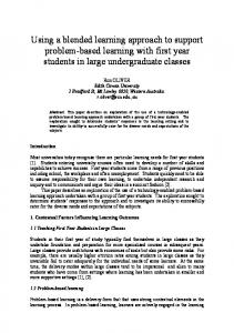
Figure 1: An overview of ZOOM approach Figure 1 shows the structure of a ZOOM model. As shown in the figure, the functional requirements derive the structural, behavioral and UI models. We will discuss notations of each model in following sections. Extra-Function Requirement(XFRs) and Environmental Requirements are two other dimensions that must be adequately addressed before an application can be successfully realized from a model[14]. The XFRs stipulate the minimum service levels that an application must provide while exercising its functional requirements and Environmental Requirements is concerned with the target runtime environment and its requirements. The middle bar of the figure show as the
Knowledge-Based Model Compilation Tools, which is the process of generating a completed application that based on knowledge like Transformation and Code Generations Rules, Transformation and Code Generation Templates, Architectural and Design Knowledge etc. We will present more details in Knowledge-based Model Compilation Tools in section 4. In the following sections, we introduce the structural, behavioral and UI model notations in ZOOM. An instantmessenger example is used to illustrate the notation of these models. Figure 2 shows the graphical view of simplified structural, behavioral and UI model for part of a instant messenger system. As shown in the part (a) and (b), the graphical representation of ZOOM Structure Model and Behavioral Model are consistent with UML-2 class diagram and state chart. In the following sections we will also present the textual representation of models shown in Figure 2.
(a) Graphical View of A Structural Model
1 1
FriendList +contacts 1
1Log +items 1
1
[evLoginSuccess]
*
LogItem +message +date +time +fromUser +toUser
Login
Idle
[evChangeInformation]
*
Contact +userID +firstName +lastName +email +chatLog
OK
Cancel
ChangeInformation
[evAddContact]
1
Password
[evExit]
[evLogin]
User +userID +userType +password +information +friends
UserID
NotLogin [evLoginFail]
*
Login
Final State
[evBeginChatting]
1
(c) Graphical View of A UI Model
Initial State
[evLogout]
1
PersonalInformation +firstName +lastName +street +city +state +zip +phone +email
[evFinishChatting]
Messenger +systemName +users
(b) Graphical View of A Behavioral Model
Add Contact
UserID FirstName LastName EMail
Add
Cancel
AddContact
Chatting
Figure 2: A ZOOM Model Example Graphic View 3.2. Structural Model The structural model defines the functional part of the system using object-oriented concepts. These models provide not only the class relations and hierarchies, but also a precise specification of the functionality of each entity. The main characteristics of ZOOM-M are formalism, object-oriented and side-effect free. ZOOM-M is also strongly typed with a semantically rich type system that supports inheritance and generic types. Comparing with the formal specification language Z, ZOOM-M provides the object-oriented concepts, which overcomes the deficiencies of Z that the representation capability limited to the mathematical logic. The textual specifications of the structural models are specified by ZOOM-M language. ZOOM-M is fully developed and implemented. It provides the formal specification capability to describe functionalities, while using a Java/C++ like syntax to make it easy to adopt by practitioners. For example, Figure 3 shows part of the textual representation of Structure Model:
typedef FriendList = List[Contact]; public struct User { invariant { userID != null } public:protected String userID; public UserType userType; protected String password; public boolean loggedIn = false; public User(String userID) requires { userID != null } ensures { this'.userID == userID }; public void login(String maskedPassword) ensures { this'.loggedIn == ( encrpt(this.password) == maskedPassword ) }; }
Figure 3: ZOOM-M example 3.3. Behavior Model The behavioral model is the central communication mechanism that links the structural models and UI models. It uses a formalized state diagram to specify the dynamic aspects of a system. This state diagram uses ZOOM-M to define the behavior of the system. Graphically, the representation of the behavioral model is consistent with a UML state chart[15,16]. This approach makes it easier for practitioners to understand and design the behavior models. In the behavior model, each action and its corresponding result is specified by pre- and post-conditions in a way that is similar to that used in the structural models. It supports both nested state and concurrent state change definitions. For example, Figure 4 shows part of the textual representation of Behavior Model: fsm Main() { state NotLogin; state Login { fsm LoginFSM() { … } }; state Idle { fsm IdleFSM() { … } }; transition initial to NotLogin; transition NotLogin to Login : evLogin; transition NotLogin to finalState: evExit; transition Login to NotLogin : evLoginFail; transition Login to Idle : evLoginSuccess; transition Idle to NotLogin : evLogout; }
Figure 4: ZOOM-FSM Example 3.4. User Interface Model Unlike UML-2 and MDA notations, ZOOM separates UI models from other aspects. This comes from the intrinsic characteristics of the UI aspect being separated from the structural and behavioral aspects. The UI typically has a tight association to a specific platform while other aspects are typically platform independent [17]. That in turn means it is better to decoupling the UI designs from the other aspects, ZOOM uses a specific UI modeling notation to achieve this other than mixing the UI design as part of programming. For example, Figure 5 shows part of the textual representation of UI Model:
Figure 5: ZOOM-UIDL Example
One advantage of this separation is that it is easy to change a UI view by only changing the UI models, while other aspects remain the same. This is even more important while developing multi-platform software system. Another advantage is that it is convenient for modeler to model the software system from the bottom to the top. While a UI model typically composite several nested sub UI models, and each of them can find the structural and behavior counterparts as a subset of the whole structural models and behavioral models. A second advantage of this separation of concerns is that we overcome the difficulties of specifying the UI together with the structural model; the UI typically has a tight association to a specific platform while the other models can be platform-independent. In its present form, UML-2 fails to enforce this separation of concerns. Such enforcement must be done by the modeler. 3.5. An Event-Based Framework for Model Integration To coordinate the activities between the structural, behavioral and UI models, ZOOM provides an event model that is processed by an event-driven framework. Events are used in the behavioral model to specify the dynamic nature of the system. Upon receiving specific types of events, the behavioral model’s finite state machine (FSM) will perform predefined operations. When users interact with the system through the user interface, UI events are generated and passed to the FSM. The FSM performs a series of state transitions based on the structural models. The FSM may trigger additional events, which include both predefined standard events and user-defined domain specific events. Those events are then sent back to the FSM, thereby driving the system. 4.
ZOOM Support Tools The most exciting benefit of the MDD approach is that designers use high levels of abstraction to build applications. This level of abstraction is closer to the customer’s view of the application instead of the technologist’s view. However, to achieve widespread support with software development practitioners, MDD must provide them the tools to help them perform their tasks. Figure 6 shows the overview of ZOOM support tools. There are three main tools set: basic language tools, model compilation as well as Validation and Verification tools. We will present more details in the following sections.
ZOOM Support Tools
Basic Language Tools
Knowledge-Based Model Compilation
Validation and Verification
Lexers and Parsers
Code Generator Type Checkers
UML Mapping Tool
Model Editor
Model Translation Tool
Knowledge Base
Animator
Automated Therem Prover
Static Analyser
Figure 6: ZOOM Support Tools Overview 4.1. Basic Language Tools These are a set of tools provide the basic language level support for ZOOM modeling including: lexers, parser, type checkers, UML mapping and model editor. These tools are the bases for more sophisticated tools like model compilation tools. We have successfully implemented the lexers, parser and type checkers. We are in the process of developing UML mapping tools and model editor. 4.2. Model Compilation Tools Model compilation, the process of generating a completed application that exposes the functional, extrafunctional, and environmental requirements described by its model, is a critical element of MDD. However, this compilation process is more complex than mere language compilation.
Not only must the generated code meet all of the functional requirements identified by its model, but the compilation process must also address issues such as the choice of architecture, data structures, and algorithms. To support such decisions, we believe that the model compilation process must be knowledge based. The key to our approach is attempting to capture the software architecture and design knowledge of human experts, codifying and representing these knowledge, and applying these knowledge in knowledge based tools to carry out fully automated model compilation. We believe that this approach offers the greatest advantages in terms of being able to a) build up and maintain the knowledge base gradually and incrementally, b) resolve often competing goals, especially in the areas of XFRs and UIs, and c) reach a solution that will satisfy all of the final application’s requirements across all three aspects (structural, behavioral, and UI). 4.2.1 Knowledge-Based Model Compilation We argue that a key to successful code generation and model compilation is that it requires a tremendous amount of knowledge in software architecture and design. A critical component of this proposal is to investigate and develop tools for knowledge-based model compilation. The amount of knowledge that goes into even the most basic architectural decision is staggering and encompasses many different areas including: available tools or frameworks, time and other resource constraints, target platform, perceived risks such as future enhancements, familiarity with trade-offs such as time-space and awareness of technical pitfalls. These issues can affect every decision during a software development effort from its inception to its delivery. The acquisition and representation of this knowledge is a complex process, particularly since there is no agreed upon solution or even criteria for any of these decisions. Each software architect will bring their own “baggage” to any software development effort that will often bias their decisions or at least their thought process. In order to make our approach a reality, and to make it more than just an improved code generation utility, we must address three critical problems: knowledge acquisition, knowledge representation, and knowledge utilization. Software architecture and design knowledge is acquired from human experts. The acquired knowledge will be codified and stored in a knowledge base. The purpose of this knowledge base is to guide the automated decision making process to derive and/or select a set of transformation rules and templates that are used to transform the models into complete applications. 4.2.2 Prototyped Model Compilation Tools Model compilation tools transform models from one level of abstraction to another. This includes model transformations as well as code generation. We have been working on developing a prototyped code generator based on ZOOM model. The code generator creates code based on the ZOOM model. Traditional code generation focused mainly on constructing the skeleton of an application based on some templates and leaving “hooks” for developers to fill in. In the MDD world, code generation is based solely on the model with some customized parameters. Because of its formal characteristics, ZOOM can derive the code from the models’ formal specifications without interactive guidance. What differentiates the ZOOM code generation process is that we intend for the process to also consider the architectural and environmental requirements in addition to the more common functional requirements. This allows “smart” code generation that can adapt its choice of implementation and algorithm to meet specified performance or security constraints and to ensure that it can execute in the appropriate target environment. 4.3. Model Validation and Verification Tools The goal of model validation and verification is to exhibit the behavior of both the structural and behavioral models at an early stage. Developers can use these tools to validate and verify their models during the design phase, when only partial models are available. The animator provides a way for designers to verify their models based on a set of formal specifications. The animator virtually “executes” models without an implementation by introducing a default model implementation that is consistent with the formal specification. Although the animator does not provide an optimized execution of the model, it does allow the designer to identify design deficiencies at an early stage. Most importantly, the animator can work equally well with either full or partial models, allowing the modeler to perform an analysis at all stages of the software development effort.
The automated theorem prover differentiates ZOOM from other software development environments. The ATP in ZOOM is optimized for the ZOOM modeling language and provides a powerful reasoning mechanism for static analysis. The static analyzer checks the consistency, validity and completeness of model components to ensure the model is both executable and reliable [18,19]. The static analyzer can check the partial implementations provided by the developer, and verify their conformance to the specification. 5.
Conclusion and future work Model-driven development is a positive step toward a general model-based approach to software engineering. ZOOM is the approach and notation we proposed for capturing formal and complete models of all aspects of applications. It provides a mechanism to integrate system views together along with their formal semantics. ZOOM supports many tools. These tools include an automated theorem prover, model animator, static analyzer, and interpreter. Other tools such as the unit test generator are either planned or currently in development. These tools serve to make MDD in general, and ZOOM in particular, more accessible to the software development community. Our future work will be focus on continuously developing the knowledge base and set of supporting tools to demonstrate the feasibility and practicality of this approach.
References [1] J. Mukerji and J. Miller, Model Driven Architecture www.omg.org/cgi-bin/doc?ormsc/2001-T 07-01 [2] D.S. Frankel, Model Driven Architecture: Applying MDA to Enterprise Computing, OMG Press, 2003 [3] B. Selic. The pragmatics of model-driven development. IEEE Software, 20(5):19–25, 2003. [4] J.Rumbaugh, I.Jacobson and G.Booch, The Unified Modeling Language reference manual , Addison-Wesley Longman Ltd, 1998. [5] J. Poole Model-Driven Architecture: Vision, Standards And Emerging Technologies ECOOP 2001 [6] Object Management Group, UML 2.0 Superstructure Specification [7] S. Mellor, A. Clark and T. Futagami Model-Driven Development IEEE Software No.5. Volume 20, 2003 [8] J. B. Wordsworth Software Development with Z Addison-Wesley 1992 [9] J. Woodcock, J. Davies, Using Z Specification, Refinement, and Proof, Prentice Hall Europe 1996 [10] C. Lopes, W. Hrsh, Separation of Concerns, technical report, Northeastern University, 1995 [11] X. Jia, The ZOOM Notation - A Reference Manual, Technical Report, DePaul University, 2004 [12] H. Liu, L. Qin, C. Jones, X. Jia, A Formal Foundation Supportinting MDD --- ZOOM Approach, CTIRS03 2003 [13] William E.McUmber and Betty H. C. Cheng, A general framework for formalizing UML with formal languages, Proceedings of the 23rd International Conference on Software engineering, 433 – 442, 2000 [14] Nelson S. Rosa, George R. R. Justo, and Paulo R. F. Cunha. A framework for building nonfunctional software architectures. In Proceedings of the 2001 ACM symposium on Applied computing, ACM Press, 2001. [15] Object Management Group, UML 2.0 Superstructure Specification [16] Mellor, Stephen and Balcer Marc, Executable UML: A foundation for model-driven architecture, Addison Wesley, Boston, MA, 2002 [17] Paulo Pinheiro da Silva and Norman W. Paton, User Interface Modeling in UMLi, IEEE SOFTWARE, 20[4]:62-69 2003 [18] X.Jia, L.Qin & H.Liu, Hypothesis-Based Approach To Detecting Runtime Violations In Java Program Using Automated Theorem Prover, 2003 Midwest Software Engineering Conference MSEC'03 Chicago, IL June, 2003 [19] J.Wang, L.Qin & X.jia A Tool Set for Design By Contract For Java, 2003 Midwest Software Engineering Conference MSEC'03 Chicago, IL June 2003