Laptop. Laptop. Laptop. Mobile Terminals. Access Network. Core Network. Under preparation ... This deals with the collection of statistics from the different RATs .... the terminal decides that the best solution is to switch back to. UMTS so as to ...
> FOR CONFERENCE-RELATED PAPERS, REPLACE THIS LINE WITH YOUR SESSION NUMBER, E.G., AB-02 (DOUBLE-CLICK HERE)
FOR CONFERENCE-RELATED PAPERS, REPLACE THIS LINE WITH YOUR SESSION NUMBER, E.G., AB-02 (DOUBLE-CLICK HERE) < architectural view of the whole validation process could be depicted as on Fig. 1.
2
Barcelona / Piraeus
MSBS Piraeus (at sites) WLAN
Laptop
Piraeus (at sites) Laptop
UMTS
Simulated Segments
PDA
Paris
Nokia 770
Internet
WiMax
Laptop Paris
HSDPA
DSP Board
Sophia and Paris Laptop Motorola Phone
WLAN Sophia Available today UMTS
H/W Components
Under preparation
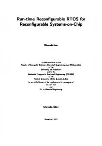
Fig. 1: Architectural view of validation approach Mobile Terminals
For the part of the work focused on the equipment (terminal) side, prototyping activities in [1] are related to the development of the requisite reconfigurable equipment management modules. The goal is to have some demonstration platforms for the reconfigurable terminal. The first one will be realized with a NOKIA 770 device (internet tablet) and a DSP board (two “versions” of DSP boards are proposed). The second reconfigurable terminal demo platform uses a Motorola mobile phone. The third one is related to a prototype for the reconfigurable base station. For the part of work focused on the network side, prototyping activities are related to the development of the algorithms for enhancing radio resource and spectrum usage. The corresponding software platforms will be integrated with network simulators on one hand and the RPE technologies on the other. C. The Reference Prototyping Environment (RPE) Finally, a global validation activity is the interconnection/ integration of the terminal and network type through the exploitation of the radio enablers. Specifically, the (so called) RPE validation will be performed through integrating validation activities performed in local demonstrations for each of the related working areas (network and terminal related), as presented in the previous section. For this purpose, the remaining of this section presents the proposed, overall demonstration target architecture, describes its availability, along with the predefined scenarios and validation criteria that are necessary for the evolution of the validation process. The RPE target architecture that is proposed herein comprises (1) a core network part, (2) a radio access network part that will comprise WLAN/WiMAX access points (APs), UMTS and GPRS/EDGE, and finally (3) several types of multi-Radio Access Technologies (multi-RAT) mobile terminals, capable of communicating in real time with the core network through the radio access network, and with Software Defined Radio (SDR) functionalities and spectrum flexibility. The radio access network comprises not only H/W components, but also simulated segments, for validating results. This target proposed validation architecture along with its timeavailability and physical location can be depicted as on Fig. 2.
Access Network
Core Network
Fig. 2: Target RPE Architecture III. TERMINAL MANAGEMENT PROTOTYPE: PLATFORM FOR DYNAMIC AND ROBUST RECONFIGURABLE CONNECTIVITY A. Reconfigurable Equipment Management System (REMS) In order to obtain some first proof of concept on the specified mechanisms for reconfigurability and validate their efficiency on operating on appropriate terminals controlled by the requisite management functionality, a prototype Reconfigurable Equipment Management System (REMS) has been implemented. Its capabilities are as follows: Discovering the available networks and determining whether a better alternative has become available. In other words, the capability of be able to identify possible entrance of a new RAT in the service area offering better opportunities (e.g. higher QoS provision, lower cost per QoS level and service). Monitoring. This deals with the collection of statistics from the different RATs in order to assess their status. Negotiating offers with the various available networks and selecting the most appropriate reconfiguration pattern for the equipment. The selection procedure may result into a switch from one network / RAT to another.
Fig. 3: REMS GUI
> FOR CONFERENCE-RELATED PAPERS, REPLACE THIS LINE WITH YOUR SESSION NUMBER, E.G., AB-02 (DOUBLE-CLICK HERE) < The REMS prototype comprises five major entities: two for the equipment side and three for the network side. The higher level on the terminal side corresponds to the CMM (Configuration Management Module) that is responsible for managing the whole reconfiguration procedure. The lower level corresponds to the CCM (Configuration Control Module) that manages the communication with the hardware. Fig. 3 shows indicatively the CMM_NS, the Negotiation & Selection module that is responsible for negotiating on offers with the available Networks and selecting the most appropriate reconfiguration pattern. Fig. 4 depicts in high-level terms the interactions between the modules of REMS prototype. In case the Monitoring and Discovery identifies a trigger for reconfiguration (service initiation, degradation of the perceived QoS level or the availability of an additional RAT/network - phase 1) it requests and acquires profile information by interacting with the Profiles module. All necessary information on the current user, application/service and equipment is obtained and information on the status of available networks is collected (phase 2). The Monitoring and Discovery module analyzes the acquired data and performs an estimation of reconfiguration costs and a filtering of the list of available networks. If a reconfiguration is necessary, the Negotiation and Selection module is triggered via a Reconfiguration Request, holding all information gathered in the previous. The Negotiation and Selection module starts the negotiation with the relative network management entities (phase 3) in order to acquire offers. Once all necessary information has been collected the optimum reconfiguration pattern is decided (phase 4). The actual reconfiguration process begins and the implementation of the selected reconfiguration pattern is carried out (phase 5). Reconfigurable Network Network Management Management Entities
CMM Reconfiguration Negotiation & Selection
Monitoring Monitoring & Discovery
Profiles & Agreements
1. Trigger ¾Service initiation ¾QoS degradation ¾Discovery of new RAT 2. Acquisition of status and profiles information, estimation of reconfiguration cost Reconfiguration Request (Available RATs information, profiles information)
3. Negotiation phase (Acquisition of network offers) 4. Selection phase 5. Reconfiguration Pattern Implementation
Fig. 4: High level view of REMS operation The most appropriate reconfiguration pattern is selected by addressing a short term optimization problem, targeted to the assignment of the user to a specific network, as well as to the assignment of the services the user is interested in, to QoS levels. The optimization problem relies on input data, such as (i) user and equipment profile information, and (ii) the offers acquired from available networks. The optimization should result to an allocation of the requested services to QoS levels and an allocation of the requested services to RATs. These allocations should optimize an objective function, associated
3
with the provided QoS levels, the utility deriving from the assignment of the user demand to high QoS levels and the pricing policies of available networks and the reconfiguration cost. Finally, the allocations should satisfy a set of constraints, such as the fact that each service should be assigned to an acceptable QoS level, the upper bound of the acceptable price should be respected and the use of the hardware resources of the equipment should be utilized. B. Draft Specification of Validation Scenarios Whereas out focus is on a Video Streaming service, the analysis is similar in the case of other services as well. For this service three reference QoS levels (high, medium, low) are considered. Furthermore, the results obtained are generic with respect to the technology considered as the “initial” network. Starting a service. In this scenario it is assumed that the terminal is connected to UMTS and the user wants to initiate a new Video Streaming service. By initiating the service the terminal will communicate with each of the available networks to acquire offers and decide on the best reconfiguration. The terminal decides that the best solution is to switch to the WLAN network because it offers the service at the highest possible level and at the lowest cost. QoS degradation. In this scenario a QoS degradation is forced in the WLAN network by means of the CMM Emulator module.Once the degradation is perceived by the terminal, the negotiation with the network support entities is triggered and the terminal decides that the best solution is to switch back to UMTS so as to obtain the service at the high QoS level. Change in profile. The Profiles module of the REMS holds information on application, user and equipment. The utility volume provides a measure of the importance to the user of a specific QoS level. In this scenario, the utility volume for the High QoS level of the Video Streaming Service is modified and (specifically) set to be equal to the utility volume of the Medium QoS level. This practically means that the only differentiation between the two QoS levels is the price offered for each. The result is that the terminal chooses to obtain the service at the Medium QoS level, since this is cheaper. Change in pricing policies. The generation of offers is based on an exponential function associated with the current load in a specific RAT. In this scenario the load in the WLAN network is increased. This leads to an increase in the pricing policies of the WLAN network. It is assumed that the user wants to initiate a Video Streaming service again. Once again by initiating the service the terminal will communicate with each of the available networks to acquire offers and decide on the best reconfiguration. This time the terminal decides that the best solution is to remain at the UMTS. Negotiation schemes. The prototype provides the possibility of using different negotiation protocols. The most straight forward negotiation scheme follows the first-price sealed bid auction, where all networks make their offers simultaneously, the best offer is selected and the offered service is taken as the agreed price. The second option is a reversed Dutch auction model, where the terminal continuously raises the price, until a network accepts it. Finally the third option is a reversed English auction model, where the prices offered by the networks are continuously lowered until the terminal accepts
> FOR CONFERENCE-RELATED PAPERS, REPLACE THIS LINE WITH YOUR SESSION NUMBER, E.G., AB-02 (DOUBLE-CLICK HERE) < one offer. In general results show that through the Dutch and English models the terminal may achieve better prices. IV. NETWORK MANAGEMENT PROTOTYPE: VALIDATION OF ENHANCED RADIO RESOURCE EFFICIENCY SCHEMES A. Draft Specification of Validation Scenarios In order to validate work related to the enhanced usage of radio resources in reconfigurable contexts, a basic draft scenario has been extracted, in the form of a general problem description, which aims at showcasing the need for reconfigurability in B3G environments, utilizing radio resources and spectrum in an efficient manner. We consider a NO disposing licenses for concurrently operating numerous RATs in a reconfigurable network segment. This segment consists of reconfigurable elements (i.e., elements that have reconfigurable transceivers, and serve numerous reconfigurable terminals). At the same time, this situation does not exclude the coexistence of other NOs in the same area, responsible for the deployment of the same or other RATs. Our target NO continuously monitors the environment in order to identify potential changes that will affect the segment’s smooth operation. Discovery is targeted to the identification of capabilities of alternate configurations. At some point, the NO identifies a reconfiguration trigger, which could be caused by several reasons (e.g., identification of possibility to provide desired quality or capacity levels more efficiently, introduction of new service, etc.). It should be noted that such triggers might be also terminal-initiated. The trigger may result in a reconfiguration of the network element/segment. The handling of the trigger may involve the consideration of offers from cooperating NOs. Concurrently, user, application and equipment profiles, as well as policies and goals that have been set by the NO, are taken into account. All these lead to the selection of the new appropriate reconfiguration. Finally, the reconfiguration is implemented (in the network segment and terminal). Reconfiguration may include the activation of RATs (potentially, after download of related software components), the configuration of resources so that to ensure their efficient usage, as well as the establishment of agreements with cooperating affiliated NOs. B. Draft Specification of Validation Criteria The scenario leads to certain questions with respect to the efficiency of reconfigurability, i.e. why reconfigurable transceivers should be deployed and how we can showcase the efficiency radio resources and spectrum utilization. We could claim in general that there are certain criteria that we should look for, when trying to examine the efficiency of reconfigurability. Specifically, one such criterion derives from the question whether users can exploit the available resources within a network segment in an optimum manner. Reconfigurability helps users to be provided seamless and ubiquitous connectivity, through offering the highest possible quality levels to the services requested. Roaming capabilities will also be extended, through the dynamic adaptation to regional contexts. Similarly, the ability to download and dynamically install software on terminals will lead to enhanced personalization features and more advanced services. Another criterion for the efficiency of resource usage
4
in a reconfigurable radio context is the required Capital of Expenditure (CAPEX) and Operational Expenses (OPEX) for the deployment of networks. Considering that a network segment disposes reconfigurable transceivers, if we assume collocation of transceivers on a base station, reconfigurability can prove itself to be significantly helpful towards an efficient use of spectrum and radio resources and reduce the necessary OPEX (less signalling) and CAPEX (less hardware). In addition, the deployment of networks with reduced CAPEX is a noteworthy advantage for NOs. C. Dynamic Network Planning and Management Prototype Reconfigurable elements dispose base stations (BS) that can (re)configure themselves, in order to be able to adapt to environmental requirements. This is achieved by having reconfigurable transceivers. These transceivers, depending on the demand requirements, may select the most appropriate RAT for operation and the most appropriate spectrum band for operation. The pertinent problem anticipated is thus called RAT-demand and QoS selection (RDQ). The overall context in which our Dynamic Network Planning and Management (DNPM) component operates and caters for the efficient management of reconfigurable network segments (MRNS), is shown on Fig. 5.
Fig. 5: Architecture of DNPM All the above raise certain issues with respect to the management of those reconfigurations. Management can be performed on a two-tier basis. In doing so, the overall reconfiguration process, through the solution of the RDQ problem can be applied to reconfigurable elements, part of a segment, controlled by a more centralized (at the segmentlevel) management entity. The generic RDQ problem [2] has as inputs monitoring and discovery information, as well as information related to profiles and policies. The RDQ optimization algorithm leads to a certain reconfiguration, i.e. allocation of RATs / spectrum to transceivers, demand to transceivers, as well as applications to QoS levels. The optimization algorithm is split into phases: (i) During the 1st phase, we assign the RATs to transceivers of the element. Configurations constitute sub-problems to be launched in parallel. (ii) During the 2nd phase, the transceivers are assigned the lowest acceptable QoS levels, for each sub-problem. (iii) In the 3rd phase, the QoS levels are augmented in a greedy manner, respecting capacity and coverage limits.
> FOR CONFERENCE-RELATED PAPERS, REPLACE THIS LINE WITH YOUR SESSION NUMBER, E.G., AB-02 (DOUBLE-CLICK HERE)