is conducted using commercial software Altair HyperWorks®. The virtual experiment of friction stir welding process is performed on the butt joint of Aluminium ...
International Journal of Engineering Research & Technology (IJERT) ISSN: 2278-0181 Vol. 4 Issue 04, April-2015
Validation of Maximum Temperature during Friction Stir Welding of Butt Joint of Aluminium Alloy by using HyperWorks Mohd Anees Siddiqui1, S. A. H. Jafri2, Shahnawaz Alam3 1,2,3
Department of Mechanical Engineering, Integral University Lucknow, INDIA
Abstract- During friction stir welding, the maximum temperature at tool workpiece interphase within acceptable limit is responsible for sound quality of FSW joint. The prediction of temperature distribution is an essential aspect in order to perform the process of friction stir welding successfully. The maximum temperature along the weldline is governed by several process parameters. In the present study, simulation of friction stir welding process is conducted using HyperWorks. The virtual experiment of friction stir welding process is performed for the butt joint of Aluminium alloy AA6061 material plates. The model predictions and results were validated with experimental data obtained from work of Zhili Feng et. al. The simulation results are in good agreement with that of experimental results. It is also observed that the temperature distribution in the FSW process is symmetrical along the welding line. Simulation performed on HyperWorks has opened new track of modeling and simulation of friction stir welding.
performed on the butt joint of Aluminium alloy AA6061 plates for the experimental data obtained by the study and experiment performed by Zhili Feng et. al. The three dimensional finite element model is developed in order to obtain maximum temperature and it is validated by comparison with the experiment.
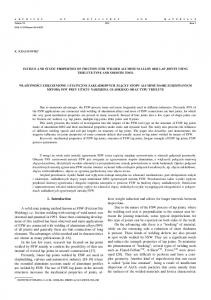
Keywords— Friction sir welding, AA6061, Simulation, Maximum Temperature, HyperWorks. Fig.1 The schematic model of friction stir welding
I. INTRODUCTION Friction stir welding is basically based on the phenomenon of generation of heat due to frictional effect. This welding technology comes within the category of solid state joining process because the maximum temperature reached in friction stir welding is less than the solidus temperature or the melting point of the parent metal. The process parameters in case of friction stir welding are rotational speed of tool, travel speed, axial load & tool geometry as they have direct impact on generation of heat at tool workpiece zone which effects the quality and strength of joint. Many research oriented experiments are conducted in this process for joining of similar and dissimilar aluminium alloys. Other than experiment based work for friction stir welding, there is a huge scope to work on simulation of friction stir welding process by finite element modelling . Several studies of friction stir welding by using commercially available softwares such as ANSYS®, ABAQUS, FORGE® and HyperWorks®. Basically this technique is adopted by scholars for the purpose of pre-experimental simulation in order to predict the response parameters. In the present study, simulation of friction stir welding process is conducted using commercial software Altair HyperWorks®. The virtual experiment of friction stir welding process is
IJERTV4IS041182
II. LITERATURE REVIEW A. Roth et. al. [1] worked on analytical approach on modelling of friction stir welding. They developed a model of friction stir welding based on the conditions of the experiment conducted by them. They calculated and analysed the coefficient of friction. Z. Zhang & H. W. Zhang [2] worked on a fully coupled thermo-mechanical model for friction stir welding. They reported that acceleration of material flow near the top surface depends upon the rotation of shoulder. They showed that temperature distribution in the friction stir welding process is symmetrical along the weld line. Hongjun Li and Di Liu [3] worked on simplified thermo-mechanical modeling of friction stir welding with a sequential FE method. They presented a methodology for modeling the transient thermal and mechanical responses without computing the heat generated by friction or plastic deformation. Through this thermal model, they showed temperature history and they found it good agreement with experimentally measured results. Mauricio & Pedro [4] worked on modeling temperature distribution in friction stir welding using the finite element method. They presented a finite element model to study the temperature distribution in plates welded by the FSW process. K. N. Salloomi et. al., [5] worked on three
www.ijert.org (This work is licensed under a Creative Commons Attribution 4.0 International License.)
817
International Journal of Engineering Research & Technology (IJERT) ISSN: 2278-0181 Vol. 4 Issue 04, April-2015
dimensional based nonlinear finite element analysis of both thermal and mechanical outputs of friction stir welded aluminium alloy-2024-T3. They used Ansys to predict thermal behaviour and thermal stresses. They found considered the effects of various heat transfer conditions at the bottom surface of the workpiece, thermal contact conductances at the work-piece and the backing plate interface on the thermal profile. Abdul Arif, et.al, [6] worked on FEM for validation of maximum temperature in friction stir welding of aluminium alloy. The developed finite element model and validated it by comparing the results with obtained by Feng et al. aluminium alloy. Armansyah et.al. [7] worked on temperature distribution in friction stir welding using finite element method by using hyperworks. They analysed heat affected zone and found that the peak temperature of friction stir welding appeared in rear of the advancing side. Binnur Gören Kiral et.al. [8] worked on finite element modeling of friction stir welding in aluminum alloys joint. They performed transient thermal finite element analyses are in order to obtain the temperature distribution in the welded aluminium plate during FSW. They analysed temperature distribution by using ansys and hyperworks. Zhang, Z., and H. W. Zhang [9] studied numerically the effect of transverse speed in friction stir welding. They analysed the effect of transverse speed on friction stir welding by using a fully coupled thermo-mechanical model. They observed that when the transverse speed was higher, the stirring effect of the welding tool became weaker which is also the reason for the occurrence of weld flaw. Prasanna et.al. [10] worked on finite element modeling for maximum temperature in friction stir welding and its validation. They studied maximum temperature developed in 304L stainless steel by using ansys
where, q0-Net power, ω-Angular Velocity, N-Rotational speed. In order to calculate the heat generation, Abdul Arif, et.al. [7] obtained the relation by dividing the net power q0 to the volume of shoulder Vsh:
Qin
q0 W ..................(3) Vsh m3
2 where Vsh Ash Rsh ts , where Ash is the area of shoulder,
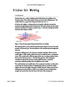
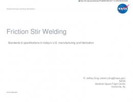
ts is the thickness. IV. EXPERIMENTAL PROCEDURE The experimental data was obtained by from the work of Zhili Feng et. al [11]. Aluminium alloy Al-6061-T6 plates with dimensions 305x152x6.35-mm were friction stir welded in the butt joint configuration. The welds were made with welding speed of 280 mm/min and the rotational speed was taken as 1250 rpm. The diameters of the shoulder and the pin were 19 mm, and 6.35 mm respectively. The welding starts at the distance of 15mm away from the edge of workpiece and the weld distance is 275mm. For this reason the length of plates are considered as 275 mm long for the present simulation work.
III. HEAT GENERATION The temperature distribution during welding is calculated by solving the governing equations for heat conduction with the application of proper boundary conditions. Frigaard et. al. [12] mentioned the following equations:
Fig.2 Friction stir welding of Al plates performed by Zhilli Feng et. al [11]
Torque Required is given as: M
MR
0
R
dM P 2 r dr 0
2 3 .....(1) PRsh 3
where, M-Interferential torque μ-co-efficient of friction R-Surface Radius P-Pressure distribution across the interface Average heat input per unit area and time
q0
MR
dM 2 N
0
IJERTV4IS041182
MR
4
dM 3 0
2
PNRsh3 .....(2) Fig.3 Dimensional details of AA-6061 plates and rigid tool for friction stir welding experiment performed by Zhilli Feng et. al
www.ijert.org (This work is licensed under a Creative Commons Attribution 4.0 International License.)
818
International Journal of Engineering Research & Technology (IJERT) ISSN: 2278-0181 Vol. 4 Issue 04, April-2015
The physical & thermal properties of Aluminium Alloy AA 6061 is shown in table 1.
TABLE 1. PHYSICAL & THERMAL PROPERTIES OF AA-6061 Property Density Melting Point Modulus of Elasticity
Values 2.7g/cm3 582-652ºC 68.9GPa
Poisons Ratio Thermal Conductivity Specific Heat Capacity
0.33 167 W/m-k 0.869J/g ºC
The finite element model was developed for simulation of friction stir welding. The model has 3200 hexahedral elements and 3907 active nodes. The FSW parameters considered by the simulation suit are pin diameter, pin height, pin rpm, pin tilt, translational speed, shoulder diameter and height. It is assumed that 90% of the work is converted into energy. The developed finite element model has several components with their defined name, no. of elements and ID range. HyperWorks provides an efficient interface for development of finite element model and analysing friction stir welding with the HyperXtrude Solver.
V. FINITE ELEMENT MODELING AND ANALYSIS OF FRICTION STIR WELDING PROCESS Altair® HyperWorks® simulation tool is used for simulation and finite element analysis of friction stir welding process. This software has a thermal conduction capability and can be used for a 3-dimensional, steady-state or transient thermal analysis. Transient finite element analysis are performed considering steady state heat source. The steps for finite element analysis of friction stir welding process are as below. 1. 2. 3. 4. 5. 6. 7.
Loading of FSW User profile Selection of Units Creation of butt weld model Loading of model to solver Inspection of materials and process parameters Running the analysis Post process results obtained in hyperview
Fig.6 Finite element model of friction stir welding process showing different displayed components such as tool, butt joint, HAZ, left plate and right plate.
The initial temperature of the workpiece is assumed equal to the ambient temperature (293K). Convection’s coefficient of 30 W/m2K is applied at the top and side surfaces of the workpiece. Since the value of conductive coefficient between the workpiece and the backing plate is unknown, convective coefficient of 300 W/m2K can be applied to the bottom surface of the work piece. The above conditions are adopted from Colegrove [13]. VI. RESULT & DISCUSSION
Fig.4 Tool & workpiece information input in HyperWeld.
In the present work, HyperWorks® is used for virtual experimentation of friction stir welding process in order to generate butt joint of Aluminium alloy AA6061 plates 305x152x6.35 (mm) as per the experimental data from the work of Zhili Feng et. al. [11]. In their work, welding length was 275 mm which is considered as length of plates in the present work. Figure 7 & 8 shows the simulated temperature contour plot showing the tool at mid position of the plates during friction stir welding of AA6061 plates. Transient finite element analysis is performed considering steady state heat source.
Fig.5 Isometric view of finite element model of friction stir welding process showing tool and workpiece along with meshing lines having 3200 hexahedral elements and 3907 active nodes.
IJERTV4IS041182
www.ijert.org (This work is licensed under a Creative Commons Attribution 4.0 International License.)
819
International Journal of Engineering Research & Technology (IJERT) ISSN: 2278-0181 Vol. 4 Issue 04, April-2015
Fig.7 Isometric view of simulated model of friction stir welding process showing temperature contours from minimum (blue) to maximum (red) values.
Fig.10 Temperature distribution for advancing side during Transient finite element analysis of friction stir welding an tool as a steady state heat source in mid of the plates.
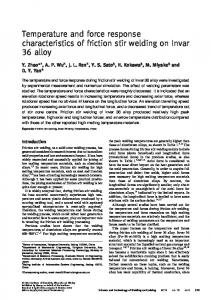
Fig. 8 Temperature distribution from top surface of the workpiece.
Figure 8 shows that the maximum temperature achieved 838K approx. at the tool workpiece interphase which is 17K below than the solidus temperature of workpiece i.e. 855K for AA6061 and it is within accepted range of maximum temperature required for friction stir welding. The peak temperature obtained by Zhilli Feng et al [11] was 845K.
Fig. 11 Comparison of Simulated temperature and experimental maximum temperature as a function of distance from weldline.
VII. CONCLUSION
Fig. 9 This figure shows different zone created during friction stir welding such as Weld Nugget Zone, Thermo-mechanical heat affected zone (TMHAZ) and Heat affected zone (HAZ)
IJERTV4IS041182
Transient finite element analysis of friction stir welding is performed by considering tool as steady state heat source in order to predict the temperature distribution during friction stir welding of Aluminium alloy AA-6061. The finite element modeling and simulation is performed by using HyperWorks. The simulation results are validated with the experimental results of Zhilli Feng et al. It is observed that the simulation results have good agreement with experimental values near the weld line. As we move away from the weldline there is variation in simulation and experimental values which may be due to different heat transfer co-efficient considered during the FSW process.
www.ijert.org (This work is licensed under a Creative Commons Attribution 4.0 International License.)
820
International Journal of Engineering Research & Technology (IJERT) ISSN: 2278-0181 Vol. 4 Issue 04, April-2015
REFERENCES (1)
(2)
(3)
(4)
(5)
(6)
(7)
(8)
(9)
(10)
(11)
(12)
(13)
A. Roth et. al., "Analytical approach on modelling of friction stir welding", Procedia CIRP 18 ( 2014 ) 197 – 202 International Conference on Manufacture of Lightweight Components – ManuLight 2014‖ Z. Zhang & H. W. Zhang, "A fully coupled thermo-mechanical model of friction stir welding", Int J Adv Manuf Technol (2008) 37:279–293 Hongjun Li and Di Liu, "Simplified Thermo-Mechanical Modeling of Friction Stir Welding with a Sequential FE Method" International Journal of Modeling and Optimization, Vol. 4, No. 5, October 2014. Mauricio & Pedro, "Modeling temperature distribution in friction stir welding using the finite element method", 20th International Congress of Mechanical Engineering, November 15-20, 2009. K. N. Salloomi et. al., "3-Dimensional Nonlinear Finite Element Analysis of both Thermal and Mechanical Response of Friction Stir Welded 2024-T3 Aluminium Plates" Journal of Information Engineering and Applications, Vol.3, No.9, 2013. Abdul Arif, et.al, ―Finite Element Modelling for Validation of Maximum Temperature in Friction Stir Welding of Aluminium Alloy‖, 3rd International Conference on Production and Industrial Engineering, CPIE- 2013, At NIT, Jalandhar, Punjab. Armansyah et.al, "Temperature Distribution in Friction Stir Welding Using Finite Element Method", World Academy of Science, Engineering and Technology, International Journal of Mechanical, Aerospace, Industrial and Mechatronics Engineering Vol:8 No:10, 2014. Binnur Gören Kıral et.al., " Finite element modeling of friction stir welding in aluminum alloys joint", Mathematical and Computational Applications, Vol. 18, No. 2, 2013. Zhang, Z., and H. W. Zhang. "Numerical studies on the effect of transverse speed in friction stir welding." Materials & Design 30.3 (2009): 900-907. P.Prasanna et. al., ―Finite element modeling for maximum temperature in friction stir welding and its validation‖ ; Int J Adv Manuf Technol; 2010. Zhili F Z. Feng, X. L. Wang, S. A. David, and P. Sklad, ―Modeling of residual stresses and property distributions in friction stir welding of aluminum alloy 6061-T6‖, 5thInternational Friction Stir Welding Symposium, Metz, France, 2004 Frigaard, Oyvind, Oystein Grong, and O. T. Midling. "A process model for friction stir welding of age hardening aluminum alloys." Metallurgical and materials transactions A 32.5 (2001): 11891200. P. Colegrove, ―3 Dimensional Flow and Thermal Modelling of the Friction Stir Welding Process, Thesis Master of Engineering Science, The University of Adelaide, January 2001
IJERTV4IS041182
www.ijert.org (This work is licensed under a Creative Commons Attribution 4.0 International License.)
821