Aug 25, 2017 - research Type 5 in the Design Research Methodology (DRM) framework .... the design space adopting a design-of-experiment (DOE) approach ...
NOTE: the following is a pre-print version of the article. For the published version of the article please reference: Panarotto, M., Wall, J., Bertoni, M., Larsson, T. C., and Jonsson, P.,2017. Value-driven simulation: thinking together through simulation in early engineering design. In: International Conference on Engineering Design ( ICED17), 21st-25th August, Vancouver, Canada.
Value-driven simulation: thinking together through simulation in early engineering design Abstract: The topic of ‘design for value’ has lately attracted a great deal of attention within the engineering design community. ‘Predicting’ the value of a future solution is however difficult, especially in early design phases. Modelling and simulation is believed to be able to support this challenging task. A simulation process for value-driven engineering design is presented. The performances of a design concept along the lifecycle are aggregated to a monetary system value function. The results of this multi-model simulation environment for value are displayed through a colour-coded CAD model for easier interaction. Verification activities indicate that enabling effective design space exploration and visualization of cause-effect relationships become important elements in order to ‘think together’ using a simulation driven design approach. Furthermore, the proposed multidisciplinary ‘value model’ fosters cross-functional knowledge sharing and collective deliberation about the value, forcing stakeholders to synthetize their perceptions about the value of a design and to discuss where conclusions differ. Keywords: Simulation, Conceptual design, Multi- / Cross- / Trans-disciplinary processes, Value-driven simulation, Design space exploration
ICED17
1
INTRODUCTION
A key need for engineering designers is to become more effective in decision-making during the early design phases, which means to be able to ‘predict’ the future impact of a design regarding a multitude of aspects. Often, engineers make extensive use of modelling and simulation, as it allows to test important characteristics long before a physical prototype is built (Bylund et al. 2004, Wall 2007). For example, Finite Element Analysis (Adams and Askenazi 2009) is used to predict how a product reacts to real-world forces, vibration, heat, and other physical effects. Literature (e.g. Isaksson et al. 2009) recognizes the importance of models as a means for verification, but stresses also the need for a broader view on how simulations are used to support new product development, i.e., utilizing simulation to guide on what to develop rather than focusing if the product does not fail regarding performance. This focus on innovation and models has resulted in a plethora of multi-domain simulations (Bertoni et al. 2016), which however still leaves designers with the challenge of making thoughtful trade-off decisions between conflicting attributes (Isaksson et al. 2013). A solution to this challenge has been explored by research in Systems Engineering (SE). Value-Driven Design (VDD) (Collopy and Hollingsworth 2011) for instance envisions the idea of aggregating all these multidisciplinary models in a ‘value model’. Such construct is intended to simulate how much customers ‘value’ certain capabilities against each other. In original formulations of VDD, the concept of optimization is pivotal, as it is appealing to think about simulating and optimizing such ‘value model’ in order to find the best design (Soban et al. 2012). However, optimization of a value model is challenging in the early design phases. The full set of data may not be available at these stages, making the results of the optimization exercise having little meaning. Still, firms that want to strengthen their value contribution focus based on simulations, to be able to identify promising designs without requiring the test of expensive physical prototypes. This study targets the need for an increased value focus by an effective use of multi-domain simulations, and has been organized around the following research question: How can simulation supports be defined to facilitate deliberation about value in early design? This question connects to one of the central concerns outlined in the VDD research agenda (Soban et al. 2012), which is related to the methodological enablers that foster a more value-oriented approach to engineering design. A set of simulation-based supports have been identified and outlined in a framework for value-driven engineering design. The deliverables of this study intend to provide insights for both research and practitioners who have the ambition to develop and test new or improved versions of such decision supports. 2
RESEARCH METHODOLOGY
The study, focused on developing a design support, can be described as a Prescriptive Study (PS) of a research Type 5 in the Design Research Methodology (DRM) framework (Blessing and Chakrabarti 2009, p.60). DRM suggest to develop a support in co-evolution mode (Blessing and Chakrabarti 2009, p.156): early, high-level requirements guide the generation of potential solutions, their evaluation leads to the generation of solution-specific requirements, which are then addressed by modifying the solution to add further detail, and so forth (Nidamarthi et al. 1997). Empirical data has been collected during meetings (held by-weekly, over a seven months period) within the frame a Swedish research project in collaboration with a road compaction equipment manufacturer. Participants were industrial experts who are working in different organization of the company (i.e. engineering, marketing, service, manufacturing) and have an active role in the selection of new product concepts. In these interactions, visual demonstrators of emerging concepts for modelling and simulation were presented, acting as a means for random stimulus (Cross 1994) to generate alternative proposals for design support. The data has been collected using field notes and reflections, which was then distributed to the participants for verification and their opportunity to change statements. The screening of the preferred support concepts was performed using a selection matrix (Ulrich and Eppinger 2011) adopting a set of evaluation criteria. The criteria were derived from the field notes by analysing the collected material using a noting patterns technique (Miles and Huberman 1994, p.245), which requires the fieldworker to generate unstructured “patterns” of statements and to add evidence to the same patterns with additional data in order to find “recurring regularities”. The following chapters
ICED17
discuss the criteria used for screening and present the preferred concepts for simulation supports, synthetized in a “simulation process for value driven engineering design”. 3
THE NEED FOR INTERACTION WITH SIMULATION MODELS AS A WAY TO ‘THINK TOGETHER’
The interactions with the industrial practitioners converged initially on the challenges related to the effective use of models to determine the value of an engineering system. A concern about the idea of running design optimization through the adoption of a ‘value model’ is related to the amount of data available in early design. To run optimization, designers would have to wait and focus the population of the value model by detailing a few design alternatives, and to optimize this value model only after a substantial set of data has been collected. In this way, decision could be based on reliable design optimization results, although to the cost of delayed decisions (i.e. increased lead time). Practitioners stressed instead the potential of cross-functional interaction to deliberate about value, using previous experience, gut feeling and a number of assumptions. In this context, professionals often show models and simulation results to express their reasoning and represent their opinion on the system under development. Models hence act as a means to ‘think together’ (Larsson 2003) to reach a shared understanding. A major concern in early decision-making is deliberating upon conflicting value attributes, especially regarding the case of trade-offs between customer requirements that are of a less tangible nature than technical system performances. A central question is whether or not simulations are able to represent conflicts in a way that allows team members to rapidly identify and solve them through discussion (Carlile 2002). The following anecdote, told by a service manager, exemplifies the challenge connected to this situation. In a previous development project, the design of the machine frame resulted in a shape that made it practically impossible for the customer to replace the water tank during the lifecycle. Earlier in the project, the service manager attempted to convince the design team regarding the negative consequence of the proposed frame design. The service manager was however unsuccessful as the engineering department was able to generate early models supporting the claim that the proposed frame design had positive impact on overall robustness as well as well as a reduced investment cost. The service manager expressed some frustration with this, as he had to wait until the design was more detailed to show that the customer would have had to lift the whole machine just for replacing the water tank. Hence, at that stage it was decided to change the whole frame design resulting in expensive and time-consuming rework. The abovementioned anecdote suggest that one group (engineering, project management) felt more ‘at home’ than the counterpart (service), because of what the models were able to represent (investment cost, structural strength). As a consequence, the service manager found it difficult to engage in the discussion, and to effectively provide arguments that shifted the balance of power towards other value contributions. This implies a high degree of risk, since designers may disregard more value-adding options in a competitive marketplace. To this regard, working with value models (or value functions) is seen as a way to exploit current models outside their specific discipline, by integration with other ‘ad hoc’ models able to represent more intangible properties of a system. The main effectiveness in the value model lies in the way that it allows cost and benefits to be ‘summed up’. Practitioners expressed a preference for a monetary value function to engage all the stakeholders with a practical, convenient measure targeting the whole system lifecycle. However, the team needs to rapidly screen from the overall value model result to influential design variables to enable collaboration and reach consensus about which parts of a large design space to focus on (Clarkson et al. 2004). A possible way to obtain these is to explore the design space adopting a design-of-experiment (DOE) approach (Giunta et al. 2003). DOE is a technique for choosing a limited set of data samples in the design space with the goal of maximizing the amount of information produced. DOE allows to predict the trends in the simulated response data, i.e. determine the relationship between design variables (factors) affecting a process and the output of the studied process. Practitioners expressed a major concern regarding the scenario of aggregating multi-domain models by means of a value model to foster cross-functional integration. Interaction and multidisciplinary collaboration through simulation is challenged by the fact that the multi-domain models are perceived by designers as ‘black-box functions’ (unknown function properties), data is vague and the exploration goals are often implicit (Salustri et al. 2008). Respondents in the case study stressed the importance of
ICED17
visualisation as a vital tool to allow users to describe the solution space. Among common examples of visualization techniques (such as scatter plots, parallel coordinates, and histogram plots), practitioners expressed an interest for the approach adopted by Bertoni and others (2013), who develop a lifecycle value representation approach connecting qualitative value scores (based on a 9-point scoring system) to the actual CAD representation of the product under analysis. Value scores are mapped to a colour scale to highlight areas that are negatively or positively affected by a new designs. This type of visualisation is based on analysis of "variation" among and between data samples to be visualised. A general method for this is analysis of variance (ANOVA), see for example (Obayashi et al. 2010, Shan and Wang 2008). 4
THE SIMULATION PROCESS FOR VALUE DRIVEN ENGINEERING DESIGN
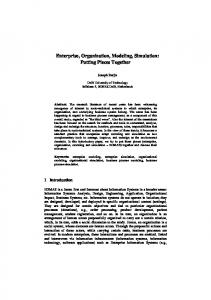
The findings from the case study led to the definition of a generic simulation process for value-driven engineering design, further detailed in the following chapter. Figure 1 depicts the simulation process. The input to the process are the results from a previous qualitative assessment loop and is composed of 6 simulation-driven areas, which are linked together to promote a stronger focus on the monetary quantification of all the aspects emerging from the qualitative analysis, even the most intangible ones. The proposed value function insists on a conceptual approach for lifecycle costing (see Gupta 1983), to emphasizes flexibility, learning and accommodate the volatility of hypothesized relationships. The Total Cost of Ownership (TCO) equation used in the case study builds on cost drivers derived from the work of Ferrin and Plank (2002).
Figure 1. The generic simulation process for value-driven engineering design
The simulation process populates this general TCO function by linking the calculated performances of a design (through CAD and functional/engineering models) to TCO items (by means of a factory model and lifecycle performance models). Each step of the process is described in the following sections, and exemplified in a case related to the redesign of a 1.7 tons asphalt compaction machine. The case focuses on the design of the front part of the machine and considered 7 main subsystems/components: drum, frame, forks, bearings, engine, engine hood, eccentric. Figure 2 shows a simplified representation indicating the position of the 7 sub-system in the design configuration.
Figure 2. Simplified representation indicating the 7 sub-systems in the case study
The process was implemented in a simulation environment where the software deploying the simulation areas (e.g. Autodesk Inventor©, Matlab©, Anylogic©) were linked together using
ICED17
MSExcel® as interface/server. Designers can define a system configuration, run the functional/engineering models and the lifecycle performance models from MS Excel©. The models take inputs from Excel, run calculations and output back to Excel. Design exploration and results visualization were implemented by means of DOE and ANOVA algorithms. The next sessions present each step in the process. Every session is introduced by the findings from the empirical study and ends explaining how the practitioners’ preferences were translated into a simulation support. 4.1 Create parameterized CAD model and run functional/engineering models In the early phases the team is interested to look at the cost and value provided by the major subsystems and components of the product under development. The objective here is to highlight which areas of the existing machine require a redesign effort. Another aspect of interest in this context is to understand how a change in one sub-system ‘propagates’ to other sub-systems and what is the overall effect on value and costs. For example, setting a bigger and more powerful diesel engine would increase the machine velocity and compaction energy provided to the ground. However, this change may require a bigger engine hood, increasing costs and negatively affecting value, as it worsen the visibility for the operator. In this context, working with functional models as a structured representation of the system under analysis is a preferred component that would facilitate such understanding process: “you want to have a systematic approach for working with functional models, with formulas (and data) that you can sum up […] you can systematically break down the requirements to components, from an overall system of the various sub-systems, in order to understand their relationships. And you can reuse the functional models, since they are very similar for almost all the machines.[…]At this stage you must also consider that the model should not be too advanced, you need to find a trade-off”. A simplified schematic description of the functional model developed in the case study is given in figure 3. For an asphalt compactor, the main functionality is the ability to compact soil. However, to be able to compact soil additional functionality such as a power supply, transmission, etcetera is needed.
Figure 3. Functional model
This functional model is populated by engineering models (for example in the form of differential equations, algebraic equations and mathematical logic) in order to estimate the performances of the system (listed on the right side of figure 3). In the case study, for a given system configuration, a compaction model (implemented in Matlab©) calculates the amount of energy per time unit which is transferred to the ground through the drum. An energy model (Matlab©) calculates required energy and associated fuel consumption for the suggested machine design and a finite element model (implemented in Abaqus©) of the frame verifies the structural strength to avoid structural failure during operation. For the population of such engineering models, geometric and technical descriptions of the major sub-systems and components under analysis is required. This information is supplied through a parametric CAD model (implemented in Autodesk Inventor©). Geometric information from the CAD model is also used to assess the visibility from the operator's position. 4.2 Calculate cost of major sub-systems and components The cost for the sub-systems of the design under analysis are estimated through the use of a factory model. The model follows an activity-based methodology (Langmaak et al. 2013), in which the cost rates of the manufacturing and assembly cells are multiplied by the operation times derived from
ICED17
scaling rules. Literature suggest to develop such models using a dynamic technique, as this allows the improvement of cost estimation by analysing queues, utilization and idle capacity costs. Furthermore, if such factory simulations are directly connected to the CAD geometry, feedback of cost estimation results can be given directly to a design team within their design environment (Jinks 2012). A major problem in traditional factory simulation models is that the logic is created on a specific case (Randell and Bolmsjo 2001), which means that the analysis of new design alternatives requires personnel and time investment to adapt the simulation model (Jinks 2012). The proposed simulation environment implements a flexible discrete-event factory simulation model (Hübl et al. 2011) developed in the Anylogic® software. The model imports input data from an MS Excel database: • Part geometries to be manufactured (e.g. frame) and purchased (e.g. engine) from CAD model • Machine groups: which machines and assembly stations are available in the factory layout • Routing: indicates the sequence for the parts across the machine groups • Manufacturing volumes, unit material costs, operation times, machine cost rates The advantage of this type of model is the ability to generate factory simulation models based on the input data for any kind of factory layout and system design. The design components enter in the simulation model and ‘route’ across their assigned machine groups and assembly stations using ‘enter’ and ‘exit’ port items available in Anylogic (Hübl et al. 2011). For example, the frame is constituted by five parts. Through the CAD geometries the weight can be calculated (via the functional model), and hence its material cost. The parts flow to a laser cutting machine, and its manufacturing cost is calculated through a scaling rule (between laser cutting time and the steel plate length and thickness). Finally, the frame moves to an assembly station, where it waits for the drum and the fork to be assembled together. The assembly cost is calculated by a scaling rule between the weight of the parts and the assembly time (finally multiplied by the assembly station cost rate). 4.3 Populate TCO function through lifecycle performance models Respondents in the case study highlight that the overall value of a system cannot be directly derived from its ‘endogenous’ performance attributes, value is very dependent of the systems impact on the customers operational process (Brathwaite 2011). For example, the value of a machine with lower fuel consumption is dependent on how much the product is used, and on the fuel price of the country where the customer is using the machine. Hence, the simulation support should enable the calculation of the system performances along the lifecycle in order to be ‘summed up’ to the overall TCO function. In the simulation process, this is done by means of ‘lifecycle performance’ models. Such models take as input the system performances calculated through the functional/engineering models and calculate their impacts on TCO. This requires the definition of a customer operational scenario (or use case), since compaction performances can differ between type of application (parking lots, large arterial roads, roundabouts and residential areas) and differ between countries (due to climate, asphalt type, support infrastructure etc). The case study implemented two lifecycle performance models based on a discrete-event simulation (DES) technique. The advantage of DES compared to static models (developed, for example, in MS Excel©) is that it allows to better model dynamic behaviours (such as queues, idle states, downtimes) as well as provides a more intuitive graphical representation. The two models were developed in the AnyLogic® software environment. The first is a ‘usage model’, which can output: • the net utilization time for the machine in a year • the net distance covered by the machine in a year • the net total fuel consumption in a year • the number of transport operations between compaction sites in a year The second module is a maintenance model which was used to understand the impact of the design on maintenance and repair operations. This model aims at calculating the increase or decrease of maintenance costs due to the introduction of new designs in comparison with a selected baseline. The model was developed to 1) calculate regular maintenance cost 2) calculate the expected repair cost and 3) estimate the average downtime, and hence the availability of the machine along its lifecycle. Figure 4 shows the graphical user interface (GUI) where the usage and maintenance models are linked to their input models (CAD and functional model) (figures are only meant to be demonstrative).
ICED17
Figure 4. Screenshot of the GUI interface linking functional and lifecycle performance models
Designers can run the linked models in sequence via the GUI and compare the selected configuration to another configuration selected as baseline, by means of TCO and its associated cost items. The GUI allows also to change the usage scenario, enabling what-if analysis (for example, a different application or an increase in fuel price during the time of ownership). Modelling relationships between systems performances and TCO items in the lifecycle performance models requires input from all the members of the cross-functional team. Additionally, it forces team members to quantify the most ‘intangible’ contributions of the design. For example, the impact of the operator's visibility on operation efficiency was modelled as reduced machine velocity, were attainable velocity is inversely proportional to the size of the blind area surrounding the machine (based on feedback from the industrial practitioners). This allows to quantify the impact of visibility on operational costs, and to make trade-off decisions with other performance attributes (such as compaction capacity). 4.4 Design space exploration through DOE Manually performed what-if analyses prohibits extensive exploration of a vast design space. To achieve the full gain of simulation-driven design, structured and automated approaches are needed. The proposed simulation process implements a semi-automated DOE tool for the exploration of the design space and presents it to the end-user through a GUI, see figure 5.
Figure 5. Screenshot of the GUI for DOE studies
Fundamental input to the GUI is a description of the studied design concept based on its parametric CAD representation. When the CAD model is created, design parameters intended to be selectable as design variables in the DOE are defined. After importing design data from the CAD model, a list
ICED17
containing all selectable variables are generated in the GUI and the user may define which of them to include in the DOE study. The next step is to define a usage scenario and choose which usage variable to vary in the study (none of the usage scenario variables are varied in the example of figure 5). After that all variables and their bounds are set an appropriate DOE method is selected. System performances and TCO items for each variable combination stated in the experimental design are then evaluated by running all the simulations (functional, factory, lifecycle) automatically in sequence. Result analysis is then performed either on a system or component level, i.e. on a higher level analysing how components effect TCO or its items or on a lower level how design variables effect component performance and visualized in a data plot. Simulation models need near to real-time performance regarding execution time to enable simulation of new scenarios during decision meeting. In most cases this is not attainable. If so, thorough design space exploration needs to be performed before hand, generating and saving design data that at a later point can be scrutinised in a collaborative manner. 4.5 Navigate through the simulation results and make decisions Linking multiple models to the final TCO equation allows the design team to explore the design space at high speed. However, the risk of using such a ‘pool of representations’ is that some models (and the associated simulation results) would be grasped by only the professionals working within the organizational function that developed them. This presents a hinder to the cross-functional knowledge sharing process. In this context, practitioners stress the importance to condense the results of simulation models in visual forms: “to be confident in this kind of a decision support, you need to understand. A way to make this easy is that you do this clearly and visually”. At the same time, the team does not only want to have the final TCO result visualized, but also to understand its main TCO items as well as the system performances that drives them: “you want an end result but still you want to keep track of why it is like that”. The proposed simulation process uses the CAD model of the design concept to visualize the value model results. In this way, the team does not need to know specific components terminology nor understand the output from a specific domain model, thus making it easier to interact. Simulation results and value scores are mapped to a colour scale to highlight components/variables that are negatively or positively affected by a new designs. A colour scale ranging from green through yellow to red is used. This colour scheme, where green is good and red is bad for the studied objective, is believed to be intuitive to the end-user making it approachable and understandable also for nonexperts. Presenting results this way enables the design team to identify trade-offs and follow cause and effect relations through the model hierarchy.
Figure 6. Screenshot, presenting results through colour coded CAD model
ICED17
A challenge here is to identify and quantify how sub-systems or components effect system performance. As multiple design variables (e.g. drum width, drum diameter, drum thickness) may be used to define a single component or sub-system (e.g. drum), the effect of these design variables must be aggregated. This is done using ANOVA. Figure 6, showing a conceptual implementation of the colour code functionality within the CAD environment, displays three levels of the model hierarchy. System performance models on the right feed the TCO item models (visible in the centre of Figure 6). These items are aggregated into the TCO measure on the left. In the example shown, the TCO model indicates that the selected engine hood has a negative impact as the engine (not visible in Figure 6) and associated engine hood are coloured bronze. Stepping down the model hierarchy shows that the main origin of the problem can be found in the operating cost model calculated from the usage scenario model (engine and hood coloured red). To understand the impact that engine selection has on operating cost, the user looks at contributions from the functional/engineering models. Selecting the operating cost in the hierarchy relevant system performance models are displayed (in the example compaction capacity, velocity and visibility). Where engine selection has a minor influence on compaction capacity and a significant positive impact on machine velocity (coloured bright green) which improves operational efficiency hence reducing operating cost. This positive effect is however counteracted by significantly reduced operator visibility (coloured dark red). Avoiding this trade-off demands finding a different engine concept, maybe looking at other technologies able to provide an engine that is both small and powerful. This type of trade-off between system performances is not always intuitive, certainly not for non-experts within the group of stakeholders. 5
DISCUSSION AND CONCLUSIONS
Verification activities point to the benefit of integrating simulations according to the process presented in this paper. In current development projects, where the system to be engineered is becoming increasingly complex, the integration of multidisciplinary simulations in a ‘value model’ becomes a ‘catalysts’ for knowledge generation and negotiation. By modelling and simulating, members are forced to synthetize their perceptions about the value of a design and to discuss where conclusions differ. Furthermore, the proposed simulation environment allows the team to ‘navigate’ through the multiple value contributions of a design alternative. A respondent takes the integration between the colour-coded CAD model and the value model as an example: “right now one thinks that CAD is a tool for drawing, but this is another concept. I think it is exiting to simulate and wander through this hierarchy of objectives”. The proposed demonstrator is considered by industrial practitioners as a step forward in making an approach that fits in the ecosystem of tools that companies have at present. In such a context, practitioners point to the need of introducing the role of a ‘value specialist’ able to understand relationships coming from the simulations that build the value model and facilitate discussion between the cross-functional members. Future work will concern to the further implementation and verification of the simulation support environment for value-driven engineering design. A major challenge is related to the population of the models, which require substantial amounts of data and expert knowledge. An interesting future research track is related on how to apply Data Mining techniques to support decision makers in populating the models part of this simulation environment. Nowadays technology makes it possible to continuously log data from a system during its entire lifecycle, and to apply data mining algorithms to discover patterns and make predictions. It is appealing to think about the ability to recognize such patterns to improve the reliability of the models integrated in the simulation scenario. REFERENCES Adams, A., and Askenazi, A. (1999). Building better products with finite element analysis. USA, On Word Press. Bertoni, A., Bertoni, M., and Isaksson, O. (2013). Value visualization in Product Service Systems preliminary design. Journal of Cleaner Production, 53, 103-117. Bertoni, M., Panarotto, M., and Larsson, T. C. (2016). Boundary objects for PSS design. Procedia CIRP, 47, 329-334. Blessing, L. T., and Chakrabarti, A. (2009). DRM: A Design Research Methodology. Springer London. Brathwaite, J. D. (2011). Value-informed space systems design and acquisition. Doctoral Dissertation, Georgia Institute of Technology.
ICED17
Bylund, N., Isaksson, O., Kalhori, V., and Larsson, T. (2004). Enhanced engineering design practice using knowledge enabled engineering with simulation methods. Proceedings of Design 2004, 8th International Design Conference. University of Zagreb. Carlile PR. A Pragmatic View of Knowledge and Boundaries: Boundary Objects in New Product Development. Organizational Science 2002;13(4):442-455. Collopy, P. D., and Hollingsworth, P. M. (2011). Value-driven design. Journal of Aircraft, 48(3), 749-759. Clarkson, P. J., Simons, C., Eckert, C. (2004). Predicting change propagation in complex design. Journal of Mechanical Design. 126(5), 788-797. Cross, N., Engineering Design Methods. Strategies for Product Design, ed. John Wiley and sons (1994). Ferrin, B. G., and Plank, R. E. (2002). Total cost of ownership models: An exploratory study. Journal of Supply chain management, 38(2), 18-29. Giunta, A.A., Wojtkiewicz, S.F. and Eldred, M.S., (2003), Overview of modern design of experiment methods for computational simulation, , 41st Aerospace Sciences Meeting and Exhibit, Reno, Nevada. Gupta, Y. P. (1983). Life cycle cost models and associated uncertainties. In Electronic Systems Effectiveness and Life Cycle Costing (pp. 535-549). Springer Berlin Heidelberg. Hübl, A., Altendorfer, K., Jodlbauer, H., Gansterer, M., and Hartl, R. F. (2011, December). Flexible model for analyzing production systems with discrete event simulation. In: Proceedings of the Winter Simulation Conference (pp. 1559-1570). Winter Simulation Conference. Isaksson O, Larsson TC, and Rönnbäck AÖ. (2009) Development of product-service systems: challenges and opportunities for the manufacturing firm. Journal of Engineering Design, 20(4), 329-348. Isaksson, O., Kossmann, M., Bertoni, M., Eres, H., Monceaux, A., Bertoni, A., Wiseall, S. and Zhang, X. (2013, June). Value- Driven Design–A methodology to Link Expectations to Technical Requirements in the Extended Enterprise. In INCOSE International Symposium (Vol. 23, No. 1, pp. 803-819). Jinks, S. (2012). Integrating supply chain simulation, component geometry, and unit cost estimation. Doctoral dissertation, University of Southampton. Langmaak, S., Wiseall, S., Bru, C., Adkins, R., Scanlan, J., and Sóbester, A., (2013). An activity-basedparametric hybrid cost model to estimate the unit cost of a novel gas turbine component. International Journal of Production Economics, 142(1), 74-88. Larsson, A., (2003). Making sense of collaboration: the challenge of thinking together in global design teams. In: Proceedings of the 2003 international ACM SIGGROUP conference on Supporting group work (pp. 153160). ACM. Miles, M. B., Huberman, A. M., (1994). Qualitative data analysis: An expanded sourcebook. London: SAGE Publications Ltd. Nidamarthi S., Chakrabarti, A., and Bligh, T. P., (1997). The significance of co-evolving requirements and solutions in the design process. In: International Conference on Engineering Design (ICED’97). Heurista, Zürich, Tampere, pp 227–230. Obayashi, S., Jeong, S., Shimoyama, K., Chiba, K., Morino, H., (2010), Multi-Objective Design Exploration and its Applications, International Journal of Aeronautical and Space Sciences, 11(4): 247-265. Randell, L.G., and G.S. Bolmsjo. (2001). Database Driven Factory Simulation: A Proof-Of-Concept Demonstrator. In: Proceedings of the 2001 Winter Simulation Conference, edited by B. A. Peters, J. S. Smith, D. J. Medeiros, M. W. Rohrer, 977-983. Piscataway, New Jersey. Rhodes, D. H., and Ross, A. M. (2016, July). A Vision for Human-Model Interaction in Interactive ModelCentric Systems Engineering. In: INCOSE International Symposium. Vol. 26, No. 1, pp. 788-802. Salustri, F.A., Eng, N.L. and Weerasinghe, J.S., (2008). Visualizing Information in the Early Stages of Engineering Design. Computer-Aided Design & Applications, 5 (1-4), 1-18. Shan, S. Wang, G.G., (2010), Survey of modelling and optimization strategies to solve high-dimensional design problems with computationally-expensive black-box functions, Structural and Multidisciplinary Optimization, 41:219–241. Soban, D. S., Price, M. A., and Hollingsworth, P. (2012). Defining a research agenda in Value Driven Design: Questions that need to be asked. Journal of Aerospace Operations, 1(4), 329-342. Ulrich, K., Eppinger, S. (2011). Product design and development (5th edition). New York: McGraw-Hill. Wall, J. (2007). Simulation-driven design of complex mechanical and mechatronic systems. Doctoral dissertation. Blekinge Institute of Technology, Karlskrona, Sweden.
ACKNOWLEDGMENTS Financial support to the Model Driven Development and Decision Support (MD3S) project from the Knowledge Foundation in Sweden is gratefully acknowledged along with the support of industrial partners.
ICED17