reflections are measured from the same location. In the literature .... adhesive in an elevated temperature cure under vacuum. For the proof-of-concept ...
Vector-based Damage Localization for Anisotropic Composite Laminates
Seth S. Kessler and Ajay Raghavan Metis Design Corporation
IWSHM-2009
ABSTRACT1 A fundamental limitation for current Structural Health Monitoring (SHM) systems is the need for distributed synchronous sensors to determine precise damage location using traditional triangulation methods. Accuracy is dictated by sensor density (quantity and proximity), which drives complexity, weight and cost to resolve reliable position. Furthermore, traditional algorithm predictions for builtup aerospace structures may be severely skewed by anisotropic laminates, integral stiffeners and/or tapers, all of which would translate to inhomogeneous timedomain behavior. This paper introduces a patented real-time method for predicting accurate damage location in complex structures using minimal SHM nodes and no information about the material or structural configuration. This vector-based localization method consists of novel sensors, algorithms and hardware to achieve a significantly more robust and efficient means of predicting damage position. Results are presented for a “blind” proof-of-concept experiment on a large composite plate using guided waves, as well as theoretical accuracy and limitations for the method. Finally, a prototype of an all-inclusive compact digital embodiment of this method is described. SHM technology will be critical to reducing the overall cost of ownership for air and spacecraft, and the present research could play an important role in implementing such a system feasibly, practically and efficiently. INTRODUCTION Structural Health Monitoring (SHM) implies the integration of a nondestructive evaluation method within a vehicle to enable the possibility of continuous remote monitoring for damage. SHM has the overall goal of improving vehicle safety and reliability while reducing maintenance and inspection-based lifeSeth S. Kessler, Metis Design Corporation, 10 Canal Park, Cambridge, MA 02141 Ajay Raghavan, Metis Design Corporation, 10 Canal Park, Cambridge, MA 02141
cycle costs [1-4]. During the course of recent research, Lamb wave methods have been proven a reliable technique to collect valuable information about the state of damage within a structure. Several investigators have successfully used Lamb waves to determine the presence and location of damage within both metallic and composite specimens [5-13]. Typically, Lamb wave methods are implemented using a distribution of piezoelectric elements propagating ultrasonic elastic waves in a “pitch-catch” mode. This results in measurements of delayed and attenuated signals along each possible actuator and sensor path, as well as scattered reflections from damage sites. This data can then be used to reconstruct damage location by using traditional triangulation calculations for affected paths if the wave velocity is known. While this methodology has shown promise, accuracy is dependent on the sensor network density. To resolve small damage precisely, a large array of sensors in close proximity must be employed, which increases the system complexity, weight and cost with additional wires, acquisition channels and volume of data. This tradeoff has presented a major obstacle to deploying a practical large-scale SHM system [14]. Furthermore, the majority of these systems typically assume that wave velocity is constant and omni-directional, which is often not the case in real aerospace composite structures. While quasi-isotropic laminates are simpler to analyze, optimized aerospace structures typically take advantage of the tailorability of composite fibers to offer superior stiffness/strength in principal bending or hoop directions along with torsional stiffness, with less emphasis on transverse properties. This creates a scenario where rather than a uniform velocity found in metallic and quasi-isotropic structures, elliptical (or even cruciform) velocity curves are produced with a strong dependence on angular orientation. In addition, built up aerospace structures can incorporate integral stiffeners or even produce ply drop-off tapered sections to achieve the desired structural configuration. These features typically accelerate or decelerate incident waves locally. All of these complications may make it difficult to use traditional time-of-flight based pitch-catch algorithms successfully to detail damage in real composite aerospace structures. To remedy these dilemmas, the present investigators have developed a patented method (US07533578) to predict and characterize accurate damage location from minimal discrete sensor node locations, without the use of any velocity information. This vector-based localization method uses a novel sensor design along with an innovative algorithm to greatly reduce the sensor density required to determine damage position. Using the described method, a vector can be drawn pointing to the damage location from a single SHM node position so long as wave velocity is known. This effectively reduces the quantity of nodes required for localization by a factor of 3 and is sufficient to determine damage coordinates for isotropic and quasi-isotropic specimens, as well as some more complex structures where velocity has been characterized as a function of orientation. By adding a second SHM node, a unique position can be identified at the intersection of the two rays, regardless of material properties or structural geometry. Furthermore, a third SHM node would provide triple redundancy by virtue of the 3 possible vector combinations. This method can be deployed actively with guided waves to determine damage location, or passively to determine position of an acoustic emission event. By increasing efficiency without sacrificing accuracy, this methodology provides a feasible path to deploy a Lamb wave-based SHM system in commercial applications.
THEORY Sensor Configuration The methodology draws much of its benefit from the fact that it is “pulse-echo” based rather than “pitch-catch.” In “pulse-echo” mode, an excitation pulse radiates from a source (omni-directional Lamb waves in the present case) and subsequent reflections are measured from the same location. In the literature, “pulse-echo” testing has been achieved using “self-sensing” circuits, which allow a single element to excite and sense simultaneously or in quick succession, as well as sideby-side sensor and actuator elements [15-18]. While both of these methods have merit, they present logistical and analytical challenges that limit their applicability to most implementations [15]. Therefore, the present investigators have patented the concept of co-located sensor and actuator elements for “pulse-echo” applications, where co-planar elements are positioned in close proximity to substantially surround each other (i.e. an actuator circumscribing a collection of sensors or the converse). These elements can be physically unique, or created virtually through selective plating or poling. The present research embodies this concept with an SHM node comprising of 4-sensor and 1-actuator elements fabricated in a deliberate pattern from a single piezoelectric wafer. Algorithms The damage site is assumed to be a guided wave scatter point described by its radial and angular position (r and φ) in a polar coordinate system, with the origin at the center of the SHM node. The time at which the peak of the wave packet originates from the damage site is ts and ti (i = 1 to 4) is the time the peak of the wave packet arrives at each of the ith sensor element positions at radius a. Distance to damage from each sensor can then be described by relating the group speed cg and the respective times of flight: (a − r cos φ ) 2 + r 2 sin 2 φ = c g2 (t1 − t s ) 2
(1)
r cos φ + (a − r sin φ ) = c (t 2 − t s )
2
(2)
(a + r cos φ ) + r sin φ = c (t 3 − t s )
2
(3)
r cos φ + (a + r sin φ ) = c (t 4 − t s )
2
(4)
2
2
2
2
2
2
2 g
2
2
2 g
2
2 g
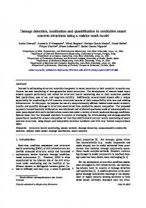
The orientation of the sensors for this derivation is shown in Figure 1. Damage
r 2 3
φ Actuator
1
a
4
Figure 1: SHM node orientation and coordinate system
Simplifying and consolidating equations (1) – (4) yields: ⎛ (t − t )( . t + t 2 − 2t s ) ⎞ ⎟ tan φ = ⎜⎜ 4 2 4 . t 3 + t1 − 2t s ) ⎟⎠ ⎝ (t 3 − t1 )(
(5)
Since the sensor pairs 1/3 and 2/4 are diagonally opposite and equidistant from the center, it is reasonable to assume that (t 4 + t 2 ) ≈ (t 3 + t1 ) . Therefore equation (5) can be simplified to: ⎛t −t ⎞ tan φ = ⎜ 4 2 ⎟ (6) ⎜ t −t ⎟ ⎝ 3 1⎠
Solving for φ yields the following pair of equations for the best error tolerance:
( (
) )
φ = atan2 t 4 − t 2 , t3 − t1 if t 4 − t 2 ≥ t3 − t1 = atan2 t3 − t1, t 2 − t 4 − π 2 otherwise
(7)
where atan2 is the four-quadrant inverse tangent function. Note that cg and ts totally drop out of equations (5) - (7), which only replies on relative time of arrival at the sensor elements. Finally, for if the wave velocity of the material is know, the radial distance would be calculated based on the average time of flight from the four sensors: ⎛t +t + t + t ⎞ r = 0.5c g ⎜ 1 2 3 4 − t a ⎟ (8) 4 ⎝ ⎠ where ta is the peak of the excitation pulse. Therefore, to solve for φ (and r for isotropic materials), each of these ti values must be mined from the sensor responses. Signals are detrended and filtered with zero-phase higher-order Butterworth filters to remove noise in the frequency bandwidth outside the excited range. The difference signal between the test and baseline signals are then produced, and convolved with the excitation signal to obtain the signal component at the central frequency. Applying the Hilbert transform to this signal component produces a signal envelope, and a peak extraction algorithm is applied to the envelope to yield the times corresponding to the peaks of the reflections. Method Limitations
The accuracies of all wave-based methods rely on several parameters that can be grouped into 3 interrelated categories: algorithm-dependant, specimen-dependant and hardware-dependant errors. While these sources of error can affect traditional wave-based methods, many of them have a more direct and significant impact on the presented method, however, due to the sensitivities of governing equations described above. The most independent of these potential sources of error are the algorithm-dependant parameters. The algorithm must be robust towards poor signal-to-noise ratios as typically seen in wave propagation. Next, the precision with which the reflection peaks can be identified by the algorithm is critical in
determining corresponding time-of-flight. Without reliable peak detection, the algorithm precision rapidly deteriorates. For specimen-dependant error, the first consideration is the ratios between size of the damage (d) to the wave mode wavelength (λ) and the distance (r). If d/λ or λ/r are too small, the damage causes weak reflection signals, leading to higher algorithm-based error. As this ratio approaches and exceeds unity, while the reflections are stronger, the “point source” assumption weakens. Consequently, sensors may detect reflections originating from different points about the damage site. The final consideration is hardware-dependant error. First, this is the main location for noise introduction, both from poor shielding and internal crosstalk. Care must be taken to guarantee good signal fidelity for the algorithm to be successful. The most fundamental limit is placed on this method by the data sampling rate, which determines how precisely the individual peaks of reflections can be resolved. For example, with a sampling rate of 10 MHz, the angular error caused by an inaccuracy in peak determination by a single sample point is ~2° for the S0 mode and ~1° for the slower A0 mode. VALIDATION SHM Node and Hardware Design
SHM nodes with 4-sensor elements and 1-actuator were fabricated to perform the prescribed tests. The node was shaped by laser from a single 20 mm diameter by 0.5 mm thick PZT-5A piezoceramic wafer, and selectively electroded so that the 5 elements could be accessed independently with a common ground. A flexible circuit was designed to make electrical connections to appropriate electrodes and suppress EMI and cross-talk, while not impeding wave propagation. Subsequently, the wafer and flex-circuit were assembled using electrically conductive filmadhesive in an elevated temperature cure under vacuum. For the proof-of-concept demonstration, an Agilent 33220 function generator and 2 Tektronix 3014B oscilloscopes were used to generate waves and measure the subsequent responses. The investigators have also developed an all-inclusive digital SHM node that incorporates all necessary sensors and hardware functionality into a miniature package, 4 cm in diameter by 6.5 mm tall, weighing ~5 g. The device will further improve the method by reducing noise sources and attenuation with local digitization [19]. This hardware is presently in testing, and was not available for the present experiments, however will be evaluated similarly in the near future. Initial Validation Experiment
An initial test matrix was completed to validate this method using a single node in an isotropic material [20]. The sensor was installed in the center of a 0.9 meter square, 3.2 mm thick Al plate, and magnets (3.2, 6.4 and 12.7 mm diameter) were separately placed 25 cm away from the node, and moved in 10° increments using shear couplant gel. Through the full range of tests, the average angular prediction error was