Abstract. We propose a vectorized Matlab implementation of the P 1-bubble/P1 finite element for the two-dimensional Stokes problem. Vectorization means that ...
Vectorized Matlab Codes for the Stokes Problem with P 1-Bubble/P 1 Finite Element Jonas Koko LIMOS, Universit´e Blaise Pascal – CNRS UMR 6158 ISIMA, Campus des C´ezeaux – BP 10125, 63173 Aubi`ere cedex, France
Abstract We propose a vectorized Matlab implementation of the P 1 -bubble/P 1 finite element for the two-dimensional Stokes problem. Vectorization means that there is no loop over triangles in the assembling operations. Numerical experiments show that our implementation is more efficient than the standard implementation with a loop over all triangles. Keywords: Finite element method, Stokes problem, Matlab. AMS subject classification: 65N30, 76D07, 65-04
1
Introduction
Matlab is an interactive environment and programming language for scientific computation. It is nowadays a widely used tool in education, engineering and research and becomes a standard tool in many areas. But Matlab is a matrix language and its distinguishing features is the use of matrices as the main data type. For best performance in large scale problems, one should take advantage of this by using vector and matrix operations. Many finite element Matlab codes are directly derived from compiled languages (Fortran, C, C++) implementations with the standard loop over triangles [1, 2, 10]. Since Matlab built-in solvers are optimized, the assembly operations are often the bottleneck in performance taking up to 99% of CPU time as we shown in [9] for linear elasticity finite element codes. We propose a vectorized Matlab implementation of the P 1 -Bubble/P 1 finite element (Mini element) for the generalized Stokes problem. Vectorization means that our code operates on array and does not use for loops for the assembling operations. Our implementation needs only Matlab basic distribution functions and can be easily modified and refined. The plan of the paper is as follows. The model problem is described in Section 2, followed by a finite element discretization in Section 3. The heart of the paper is the element matrices calculation in Section 4 and the assembling functions in Section 5. Numerical experiments are carried out in Section 6. The Matlab program used for numerical experiments are given in the appendix. 1
2
2
2
THE MODEL PROBLEM
The model problem
Let Ω be a two-dimensional domain with Lipschitz-continuous boundary Γ = ∂Ω. Consider in Ω the Stokes problem αu − ν∆u + ∇p = f ,
in Ω,
(2.1)
∇ · u = 0,
in Ω,
(2.2)
D
u = u ,
on Γ,
(2.3)
where u = (u1 , u2 ) is the velocity vector, p the pressure and f = (f 1 , f2 ) the field of external forces. In equation (2.1), α ≥ 0 is an arbitrary constant. If α = 0, then equations (2.1)-(2.3) turn to be the classic Stokes problem. If α > 0, then equations (2.1)-(2.3) turn to be a generalized Stokes problem encountered in time discretization of Navier-Stokes equations (see e.g. [7, 8]). The constant ν > 0 is the kinematic viscosity. We need functional spaces � ViD = v ∈ H 1 (Ω)2 : v = uD on Γ , V D = V1D × V2D , Vi = H01 (Ω)2 , V = V1 × V2 , � � Z 2 q dx = 0 , P = q ∈ L (Ω) : Ω
and bilinear forms ai (ui , vi ) = α(ui , vi )Ω + ν(∇ui , ∇vi )Ω , i = 1, 2 a(u, v) =
2 X
ai (ui , vi ).
i=1
The variational formulation of the Stokes problem (2.1)-(2.3) is as follows: Find (u, p) ∈ V D × P such that: a(u, v) − (p, ∇ · v)Ω = (f , v)Ω , −(q, ∇ · u)Ω = 0,
3
∀v ∈ V,
∀q ∈ P.
(2.4) (2.5)
Finite element discretization
For the finite element discretization of (2.4)-(2.5), we have to chose a finite element pair for the velocity field and the pressure. This choice cannot be arbitrary but must satisfy the inf-sup condition [4, 5]. In this paper we study the discretization of the Stokes problem (2.1)-(2.3) by the finite element pair P 1 -bubble/P 1 (the so-called mini-element), introduced by Arnold, Brezzi and Fortin [3]. This element leads to a relatively low number of degrees of freedom with a relatively good approximate solution.
3
3
FINITE ELEMENT DISCRETIZATION
Let Th be a triangulation of Ω and T a triangle of T h . We define the space associated to the bubble by n o ¯ ∀T ∈ Th , vh|T = xb(T ) . Bh = v h ∈ C 0 (Ω); We also defined the discrete function spaces � ¯ v h|T ∈ P 1 , ∀T ∈ Th ; v h|Γ = 0 , Vih = v h ∈ C 0 (Ω); � ¯ v h|T ∈ P 1 , ∀T ∈ Th ; v h|Γ = uD , VihD = v h ∈ C 0 (Ω); ih � � Z 0 ¯ 1 Ph = qh ∈ C (Ω); qh|T ∈ P , ∀T ∈ Th ; : qh dx = 0 , Ω
and we set Xih = Vih ⊕ Bh ,
D Xih = VihD ⊕ Bh D D XhD = X1h × X2h .
Xh = X1h × X2h ,
In XhD , the approximate Dirichlet boundary condition must satisfy the flux condition Z uD h · ndx = 0 Ω
where n is the unit outward normal to Ω. With the above preparations, the discrete variational problem reads as follows. Find (uh , ph ) ∈ XhD × Ph such that a(uh , v h ) − (ph , ∇ · v h )Ω = (f , v h )Ω −(qh , ∇ · uh )Ω = 0
∀vh ∈ Xh ,
∀qh ∈ Ph .
(3.1) (3.2)
For a given triangle T , the velocity field u h and the pressure ph are approximated by linear combinations of the basis functions in the form u(x) =
3 X
φi (x)ui + ub φb (x),
3 X
φi (x)pi ,
i=1
p(x) =
i=1
where ui and pi are nodal values of u and ph while ub is the bubble value. For the finite element pair P 1 -bubble/P 1 , the basis functions are defined by φ1 (x) = 1 − x − y,
φ2 (x) = x,
If we set u ¯i = f¯i =
φ3 (x) = y, �
�
ui uib fi fib
�
�
φb (x) = 27φ1 (x)φ2 (x)φ3 (x).
,
i = 1, 2
,
i = 1, 2
4
4
ELEMENT MATRICES
the system (3.1)-(3.2) can be rewritten in the following algebraic form ¯t A¯ 0 −B f¯1 u ¯1 1 ¯t A¯ −B ¯2 = f¯2 0 2 u ¯ 1 −B ¯2 0 −B 0 p
(3.3)
¯ + R, ¯ with M ¯ the mass matrix and R ¯ the stiffness matrix. The matrix B ¯i is where A¯ = M the divergence submatrix associated with the ith partial derivative, i.e. ¯i ≡ (qh , ∂i uih ), B
i = 1, 2.
To create the algebraic system (3.3), the discrete system (3.1)-(3.2) is evaluated over each triangle to obtain the element matrices Z (T ) ¯ αφi φj dx, Mij = ¯ (T ) = R ij ¯ (T ) = B ij (T ) f¯i =
Z
Z Z
T
ν∇φi · ∇φj dx, T
∂1 φi φj dx + T
Z
∂2 φi φj dx, T
f φi dx, T
Then assembling operations consist of direct-summing the element matrices over the do¯ = (M ¯ ij ), R ¯ = (R ¯ ij ), B ¯ = (B ¯ij ) and f¯ = (f¯i ) main Ω to obtain the global matrices M ¯ ij M
=
X
¯ (T ) , M ij
T ∈Th
¯ ij R
=
X
¯ (T ) , R ij
T ∈Th
¯ij B
=
X
¯ (T ) , B ij
T ∈Th
f¯i =
X
(T ) f¯i .
T ∈Th
¯ , R, ¯ B ¯ i and the right-hand In the next sections we detail the assembly of the matrices M ¯ side f.
4
Element matrices
In this section, we compute element matrices and vectors. To simplify, we drop the superscript (T ) on element matrices and vectors.
4
5
ELEMENT MATRICES
4.1
Element stiffness and mass matrices
For a triangle T , let {(xi , yi )}i=1,2,3 be the vertices and {φ}i=1,2,3 the corresponding basis functions. The gradient of φi are given by
−1 1 1 1 0 0 y2 − y 3 x3 − x 2 1 y3 − y 1 x1 − x 3 , ∇φt2 = x1 x2 x3 1 0 = 2|T | y1 − y 2 x2 − x 1 0 1 y1 y2 y3 ∇φt3 ∇φt1
(4.1)
where |T | is the area of T given by � � x2 − x 1 x3 − x 1 2|T | = det = (x2 − x1 )(y3 − y1 ) − (x3 − x1 )(y2 − y1 ). y2 − y 1 y3 − y 1 Let us introduce the following notations xij = xi − xj , and x(T )
yij = yi − yj ,
x32 = x13 , x21
y (T )
i, j = 1, 2, 3,
(4.2)
y23 = y31 . y12
(4.3)
The vectors x(T ) and y (T ) are the keystone of our Matlab vectorized codes. Indeed, all matrices and vectors involve x(T ) and y (T ) . The main advantage of using x(T ) and y (T ) is that they can be compute simultaneously on all triangle using vectorized operators. We easily verify, from (4.1) and (4.3), that (∂x φi ) =
1 (T ) y , 2|T |
(∂y φi ) =
1 (T ) x , 2|T |
(T ) (T )
|T | = (x3 y1
(T ) (T )
− x2 y3 )/2.
(4.4)
¯ for 1 ≤ i, j ≤ 3, is given by An entry of the element stiffness matrix R, Z � ν � (T ) (T ) (T ) (T ) ¯ . yi yj + x i xj Rij = ν∇φi · ∇φj dx = 4|T | T
¯ ij )i,j=1,...,3 , the nonbubble part of R, ¯ we deduce that If we set R = (R � ν � (T ) (T ) t R= y (y ) + x(T ) (x(T ) )t . 4|T |
(4.5)
¯ is symmetric, it remains to compute R ¯ bj , for j = 1, 2, 3, b. A straightforward Since R calculation yields 3 X 9 ¯ Rbj = |T | ∇φi = 0, j = 1, 2, 3. 4 i=1
4
6
ELEMENT MATRICES
For the diagonal entry corresponding to the bubble (i.e. i = j = b) we have Z ¯ 272 ∇(φ1 φ2 φ3 ) · ∇(φ1 φ2 φ3 )dx Rbb = ν T
= =
� 81 ν|T | |∇φ1 |2 + |∇φ2 |2 + |∇φ3 |2 + ∇φ1 ∇φ2 + ∇φ1 ∇φ3 + ∇φ2 ∇φ3 10 � 81 ν|T | |∇φ1 |2 + |∇φ2 |2 + ∇φ1 · ∇φ2 =: ωR . (4.6) 10
With the above results, the element stiffness matrix is then � � ¯= R 0 R . 0 ωR
¯ ij )i,j=1,...,3 the nonbubble part of the mass As for the stiffness matrix, we set M = ( M matrix. A direct calculation yields ( α if i = j, 6 |T | Mij = α elsewhere. 12 |T | The bubble part of the mass matrix is given by ¯ bj M
=
¯ bb = M
3α |T |, j = 1, 2, 3, 20 81α |T | =: ωM . 280
(4.7)
The element mass matrix is therefore ¯ = M where
�
M zt
z ωM
�
,
1 3 z = α|T | 1 . 20 1
Finally, the element stiffness/mass matrix A¯ is � � A z ¯ A= . zt ω
where we have set A = R + M and ω = ωR + ωM . From (4.1), (4.3) and (4.6)-(4.7) � 81α 81ν � (T ) 2 (T ) (T ) (T ) (T ) (T ) 2 (T ) 2 (T ) 2 + ω= |T |. (x1 ) + (y1 ) + (x2 ) + (y2 ) + x1 x2 + y1 y2 40|T | 280
4
7
ELEMENT MATRICES
4.2
Element divergence matrix
A direct integration yields the element divergence matrix −s∇φ1 −s∇φ2 −s∇φ3 t∇φ1 ¯ = [−B ¯1 − B ¯2 ] = |T | −(∇ · uh , qh ) ≡ −B −s∇φ1 −s∇φ2 −s∇φ3 t∇φ2 −s∇φ1 −s∇φ2 −s∇φ3 t∇φ3
where s = 1/3 and t = 9/20. We then set ∂i φ1 ∂i φ2 ∂i φ3 |T | Bi = ∂i φ1 ∂i φ2 ∂i φ3 , 3 ∂i φ1 ∂i φ2 ∂i φ3
and
Bib = so that
∂i φ1
9|T | ∂i φ2 , 20 ∂i φ3
¯ i = [Bi − Bib ], B
i = 1, 2,
(4.8)
i = 1, 2;
(4.9)
i = 1, 2.
From (4.8), the entries of the divergence submatrix B 1 are given by B1ij =
|T | ∂1 φi , 3
i, j = 1, . . . , 3.
Using (4.3) and (4.4), the element divergence submatrix B 1 becomes
B1 =
(y (T ) )t
(4.10)
B 2 is
(4.11)
1 (T ) t (y ) . 6 (y (T ) )t
In the same way, the element divergence submatrix (T ) t (x ) 1 (T ) t B2 = (x ) 6 (x(T ) )t
.
Similar calculations on the divergence submatrices associated with the bubble yield B1b =
9 (T ) y , 40
B2b =
9 (T ) x . 40
(4.12)
4
8
ELEMENT MATRICES
4.3
Element right-hand side
The contribution of the source term f i , in nonbubble terms, is given by 1 |T | (T ) fiT 1 , i = 1, 2, 3 fi = 3 1
(4.13)
where fiT is a mean value of fi on T , e.g.
fiT = (fi (x1 ) + fi (x2 ) + fi (x3 ))/3. The bubble terms of the right-hand side are Z 9 (T ) fi φb dx = |T |fiT , fib = 20 T
4.4
i = 1, 2.
(4.14)
Elimination of the bubble unknowns
With the element matrices and vectors obtained in the previous subsections, the 11 × 11 element system corresponding to (3.3) is A z 0 0 −B1t f1 u1 t ω 0 0 B1b u1b f1b zt 0 0 A z −B2t u2 = f2 . t t 0 z ω B2b u2b f2b 0 p 0 −B1 B1b −B2 B2b 0 To reveal diagonal blocks, this system can be rearranged as follows f1 u1 A 0 z 0 −B1t t A 0 z −B2 u2 f2 0 t u1b = f1b zt 0 ω 0 B1b t zt 0 ω B2b u2b f2b 0 0 p −B1 −B2 B1b B2b 0
.
(4.15)
We can now eliminate the bubble unknowns u 1b and u2b since they correspond to diagonal blocks (the ω blocks). From (4.15) 3 and (4.15) 4 , we deduce that t u1b = (f1b − B1b p − z t u1 )/ω,
u2b = (f2b −
t B2b p
t
− z u2 )/ω, .
(4.16) (4.17)
Substituting (4.16) and (4.17) into (4.15) 1 , (4.15) 2 and (4.15) 5 we obtain a linear system in (u1 u2 p)t whose matrix is t A − ω −1 zz t 0 −B1t − ω −1 zB1b t 0 A − ω −1 zz t −B2t − ω −1 zB2b (4.18) t + B Bt ) −B1 − ω −1 B1b z t −B2 − ω −1 B2b z t −ω −1 (B1b B1b 2b 2b
5
9
ASSEMBLY OF THE MATRICES
and the right-hand side
f1 − ω −1 zf1b f2 − ω −1 zf2b −ω −1 (B1b f1b + B2b f2b )
.
(4.19)
The subvectors and submatrices in (4.18)-(4.19) are computed using x (T ) and y (T ) . For example, if we set t t E = −ω −1 (B1b B1b + B2b B2b ), then, using (4.3) and (4.12), the element pressure matrix is � 81 � (T ) (T ) t E=− x (x ) + y (T ) (y (T ) )t . 1600ω
In the same way, if we set
e1 = B1 + ω −1 B1b z t , B
then, using (4.3) and (4.10), the element divergence submatrix are 1 e1 = 1 1 (y (T ) )t + 9 y (T ) z t . B 6 40ω 1
5
Assembly of the matrices
Before presenting the assembling functions, we have to present the data representation used for the triangulation. For the mesh, nodes coordinates and triangle vertices are stored in two arrays p(1:np,1:2) and t(1:nt,1:3), where np is the number of nodes and nt the number of triangles. The array t contains for each element the node numbers of the vertices numbered anti-clockwise. Dirichlet boundary conditions are provided by a list of nodes and a list of the corresponding prescribed boundary values. Neumann boundary nodes are provided by an array ibcneum(1:nbcn,1:2) containing the two node numbers which bound the corresponding edge on the boundary. Then, a sum over all edges E results in a loop over all entries of ibcneum. Note that Matlab supports reading data from files in ASCII format (Matlab function load) and there exists good mesh generators written in Matlab, see e.g. [11]. Matlab function 4.1 assembles the matrix (4.18) using the traditional looping approach. The optional argument nn is used to preallocate the storage array. This implementation, directly derived from compiled languages like Fortran or C/C++, produces a very slow code in Matlab for large size meshes due to the loop for. Our aim is to replace the loop over triangles by constant loops. Matlab function 4.2 assembles the matrix (4.18) using a vectorized code: 1. Area of triangles are computed in a fast way using the vectorized operator ”.*” 2. The element vectors x(T ) , y (T ) , z and the constant ω are computed for all triangles simultaneaously.
5
ASSEMBLY OF THE MATRICES
10
3. Mass and stiffness matrix are assembled. For the mass matrix, only the lower triangular part is assembled. The upper triangular part is obtained by transposition. 4. Divergence submatrices (B1 , B2 ), pressure matrix E and the additional velocity matrix zz t are assembled. 5. The final matrix (4.18) is created in a quite natural way. Remark 5.1. The pressure being defined up to a constant, the pressure matrix E must be made coercive. The easiest is to impose that p = 0 at an arbitrary node. An alternative way is to add a small (positive) diagonal matrix to the pressure matrix E. The Matlab function 5.1 assembles the right-hand side (4.19) with the traditional looping aproach while the function 5.2 assembles the right-hand side with vectorized Function 4.1 Assembly of the matrix: loop over triangles function A=stok2dp1bmat2(p,t,alpha,nu,nn) %STOK2DP1BMAT2 Stokes problem with P1-Bubble/P1 element % Assembly of the matrix np=size(p,1); nt=size(t,1); Z=zeros(3,3); Mel=(1/12)*[2 1 1; 1 2 1; 1 1 2]; % 1. loop over all triangles if (nargin==5), A=sparse(3*np,3*np,nn); else, A=sparse(3*np,3*np); end for ih=1:nt it=[t(ih,1:3), np+t(ih,1:3), 2*np+t(ih,1:3)]; % triangles area x21=p(t(ih,2),1)-p(t(ih,1),1); y12=p(t(ih,1),2)-p(t(ih,2),2); x32=p(t(ih,3),1)-p(t(ih,2),1); y23=p(t(ih,2),2)-p(t(ih,3),2); x13=p(t(ih,1),1)-p(t(ih,3),1); y31=p(t(ih,3),2)-p(t(ih,1),2); tarea=(x21*y31-x13*y12)/2; % x^(T), y^(T), z and omega xt=[x32; x13; x21]; yt=[y23; y31; y12]; zt=(3/20)*alpha*tarea*ones(3,1); omega=(81/40)*nu*(y23^2+x32^2+y31^2+x13^2+y23*y31+x32*x13)/tarea... +(81/280)*alpha*tarea; % element stiffness and mass matrices: A-zz^t Ah=alpha*tarea*Mel+nu*(0.25/tarea)*(xt*xt’+yt*yt’)-zt*zt’/omega; % element divergence/stabilization matrices B1=-(1/6)*[yt’; yt’; yt’]-(9/(40*omega))*zt*yt’; B2=-(1/6)*[xt’; xt’; xt’]-(9/(40*omega))*zt*xt’; E=-(81/(1600*omega))*(yt*yt’+xt*xt’); % element P1-bubble/P1 matrix and assembly Ael=[Ah Z B1’; Z Ah B2’; B1 B2 E ]; A(it,it)=A(it,it)+Ael; end
5
ASSEMBLY OF THE MATRICES
Function 4.2 Assembly of the matrix: vectorized code function A=stok2dp1bmat(p,t,alpha,nu) %STOK2DP1BMAT Stokes problem with P1-Bubble/P1 element % Assembly of the matrix np=size(p,1); % 1. triangles area x21=p(t(:,2),1)-p(t(:,1),1); y12=p(t(:,1),2)-p(t(:,2),2); x32=p(t(:,3),1)-p(t(:,2),1); y23=p(t(:,2),2)-p(t(:,3),2); x13=p(t(:,1),1)-p(t(:,3),1); y31=p(t(:,3),2)-p(t(:,1),2); tarea=(x21.*y31-x13.*y12)/2; % 2. x^(T), y^(T), z^(T) and omega xt=[x32 x13 x21]; yt=[y23 y31 y12]; zt=(3/20)*alpha*tarea; omega=(81/40)*nu*(y23.^2+x32.^2+y31.^2+x13.^2+y23.*y31+x32.*x13)./tarea... +(81/280)*alpha*tarea; % 3. assembly of stiffness and mass matrices Ah=sparse(np,np); for i=1:3 for j=1:i Ah=Ah+sparse(t(:,i),t(:,j),alpha*tarea/12,np,np); end end Ah=Ah+Ah.’; for i=1:3 for j=1:3 Ah=Ah+sparse(t(:,i),t(:,j),(nu/4)*xt(:,i).*xt(:,j)./tarea,np,np)... +sparse(t(:,i),t(:,j),(nu/4)*yt(:,i).*yt(:,j)./tarea,np,np); end end % 4. assembly of A-zz^t, divergence and pressure matrices B1=sparse(np,np); B2=sparse(np,np); E=sparse(np,np); for i=1:3 for j=1:3 Ah=Ah-sparse(t(:,i),t(:,j),zt.*zt./omega,np,np); B1=B1-sparse(t(:,i),t(:,j),yt(:,j)/6+(9/40)*yt(:,i).*zt./omega,np,np); B2=B2-sparse(t(:,i),t(:,j),xt(:,j)/6+(9/40)*xt(:,i).*zt./omega,np,np); E=E-sparse(t(:,i),t(:,j),(81/1600)*yt(:,i).*yt(:,j)./omega,np,np)... -sparse(t(:,i),t(:,j),(81/1600)*xt(:,i).*xt(:,j)./omega,np,np); end end % 5. Final matrix Z=sparse(np,np); A=[Ah Z B1’; Z Ah B2’; B1 B2 E ];
11
6
12
NUMERICAL EXPERIMENTS
code.
6
Numerical experiments
In two-dimensional incompressible fluid problems, it is usual to display the stream-lines. If the domain Ω is bounded and simply connected, in order to compute the stream-function ψ, we have to solve the Poisson-Neumann problem −∆ψ = ω, in Ω,
(6.1)
∂n ψ = −u · τ,
(6.2)
where ω = ∂1 u2 − ∂2 u1 is the vorticity and τ the counter-clockwise oriented unit tanget vector at Γ. Problem (6.1)-(6.2) has a unique solution in H 1 (Ω)/R and leads to the algebraic system Rψ = B2 u1 − B1 u2 where R is the Laplacian matrix (4.5), B 1 and B2 the divergence matrices (4.10)-(4.11). As for the pressure equations, we impose ψ = 0 at an arbitrary node to ensure the uniqueness. Function 5.1 Assembly of the right-hand side: loop over triangles function b=stok2dp1brhs2(p,t,alpha,nu,f1,f2) %STOK2DP1BRHS P1-Bubble/P1 element %Assembly of the right-hand side np=size(p,1); nt=size(t,1); % loop over all triangles b=zeros(3*np,1); for ih=1:nt it=[t(ih,1:3), np+t(ih,1:3), 2*np+t(ih,1:3)]; % triangles area x21=p(t(ih,2),1)-p(t(ih,1),1); y12=p(t(ih,1),2)-p(t(ih,2),2); x32=p(t(ih,3),1)-p(t(ih,2),1); y23=p(t(ih,2),2)-p(t(ih,3),2); x13=p(t(ih,1),1)-p(t(ih,3),1); y31=p(t(ih,3),2)-p(t(ih,1),2); tarea=(x21*y31-x13*y12)/2; % (f1,f2) at the center of triangles f1t=(f1(t(ih,1))+f1(t(ih,2))+f1(t(ih,3)))/3; f2t=(f2(t(ih,1))+f2(t(ih,2))+f2(t(ih,3)))/3; % x^(T), y^(T), z and omega xt=[x32; x13; x21]; yt=[y23; y31; y12]; zt=(3/20)*alpha*tarea*ones(3,1); omega=(81/40)*nu*(y23^2+x32^2+y31^2+x13^2+y23*y31+x32*x13)/tarea... +(81/280)*alpha*tarea; % element right-hand side f1b=(9/20)*tarea*f1t/omega; f2b=(9/20)*tarea*f2t/omega; b1=(1/3)*f1t*tarea*ones(3,1)-f1b*zt; b2=(1/3)*f2t*tarea*ones(3,1)-f2b*zt; bb=(9/40)*f1b*yt+(9/40)*f2b*xt; % assembly b(it)=b(it)+[b1; b2; bb]; end
6
13
NUMERICAL EXPERIMENTS
Function 5.2 Assembly of the right-hand side: vectorized code function b=stok2dp1brhs(p,t,alpha,nu,f1,f2) %STOK2DP1BRHS P1-Bubble/P1 element: %Assembly of the right-hand side np=size(p,1); % 1. (f1,f2) at the center of triangles if (length(f1)==np), f1t=(f1(t(:,1))+f1(t(:,2))+f1(t(:,3)))/3; else, f1t=f1; end if (length(f2)==np), f2t=(f2(t(:,1))+f2(t(:,2))+f2(t(:,3)))/3; else, f2t=f2; end % 2. triangles area x21=p(t(:,2),1)-p(t(:,1),1); y12=p(t(:,1),2)-p(t(:,2),2); x32=p(t(:,3),1)-p(t(:,2),1); y23=p(t(:,2),2)-p(t(:,3),2); x13=p(t(:,1),1)-p(t(:,3),1); y31=p(t(:,3),2)-p(t(:,1),2); tarea=(x21.*y31-x13.*y12)/2; % 3. x^(T), y^(T), z and omega xt=[x32 x13 x21]; yt=[y23 y31 y12]; zt=(3/20)*alpha*tarea; omega=(81/40)*nu*(y23.^2+x32.^2+y31.^2+x13.^2+y23.*y31+x32.*x13)./tarea... +(81/280)*alpha*tarea; % 4. assembly of the right-hand side f1b=(9/20)*tarea.*f1t./omega; f2b=(9/20)*tarea.*f2t./omega; b1=sparse(np,1); b2=sparse(np,1); bb=sparse(np,1); for i=1:3 b1=b1+sparse(t(:,i),1,(1/3)*f1t.*tarea-f1b.*zt,np,1); b2=b2+sparse(t(:,i),1,(1/3)*f2t.*tarea-f2b.*zt,np,1); bb=bb-sparse(t(:,i),1,(9/40)*f1b.*yt(:,i)+(9/40)*f2b.*xt(:,i),np,1); end b1=full(b1); b2=full(b2); bb=full(bb); % 5. right-hand side b=[b1; b2; bb];
6.1
Example 1: Test case with exact solution
We consider the domain Ω = (0, 1) × (0, 1) and we take α = 1 and ν = 1 in 2.1. The right-hand side in (2.1) is adjusted such that the exact solution is u1 (x, y) = − cos(2πx) sin(2πy) + sin(2πy), p(x, y) = 2π(cos(2πy) − cos(2πx)),
u 2 (x, y) = sin(2πx) cos(2πy) − sin(2πx), (6.3) (6.4)
with the boundary condition u = 0 on Γ. The domain Ω is first discretized by a uniform mesh of size h = 1/16 (289 nodes and 512 triangles in the fine mesh). This initial mesh is successively refined to produce meshes with sizes 1/32, 1/64, 1/128 and 1/256 (respectively 1089/2048, 4225/8192, 16641/32768 and 66049/131072 nodes/triangles). We report in Table 1 the distances ku − u h kL2 and ku − uh kH 1 + kp − ph kL2 between the exact solution (6.3)-(6.4) and the approximate solution using the vectorized assembling functions stok2dp1bmat and stok2dp1brhs. The distances are computed using a 13-point Gaussian quadrature. We use (4.16)-(4.17) to compute the value of the bubble. One can notice that ku − u h kL2 (Ω) → 0 and ku − uh kH 1 (Ω) +
6
14
NUMERICAL EXPERIMENTS
kp − ph kL2 (Ω) → 0 as the mesh size h goes to zero and the convergence rates are close to theoretical ones (2 and 1, respectively, see e.g. [3, 6, 12]). Mesh size 1/16
ku − uh kL2
Rate
4.8779 ×
10−2
1.2431 ×
10−2
ku − uh kH 1 + kp − ph kL2 1.3207 ×
1.97 1/32
1.17 5.8598 ×
10−1
2.7305 ×
10−1
1.3064 ×
10−1
6.3437 ×
10−2
1.99 1/64
3.1193 ×
10−3
7.8022 ×
10−4
1.10
1.99 1/128
1.06
1.99 1/256
1.9550 ×
Rate
100
1.00
10−4
Table 1: Errors and convergence rates To compare fairly both strategies (traditional looping and vectorized), we have used the assembling function 4.1 with its fifth optional argument to preallocate the array storing the matrix before the looping process. We have just used the number of nonzeros elements in the matrix assembled with the vectorized function 4.2 as the fifth optional argument. Preallocation prevents Matlab from having to resize an array each time we enlarge it. To know the percentage of computing effort the assembling functions take, we have run the Matlab program A.1 with the Matlab command profile which records informations about execution time, number of calls, parent functions, child functions, code line hit count, etc. We report in Tables 2-3 the performances of both assembling functions. In terms of computing effort taken by the assembling functions, it appears clearly that stok2dp1bmat2 is the bottleneck of the program with up to 99% of the computational time spent in the assembling process. In contrast, for large size meshes, percentage of computing effort taken by stok2dp1bmat is reasonable with major computational time spent in solving the linear system. Number of triangles
512
2048
8192
32768
131072
CPU time (Sec.)
0.47
3.57
47.45
1223.37
>15000
73.2%
87.8%
96.1%
99.2%
>99.7%
Assembly
Table 2: CPU time and percentage of computing effort taken by the standard assembling function stok2dp1bmat2.m
6
15
NUMERICAL EXPERIMENTS
Number of triangles
512
2048
8192
32768
131072
CPU time (Sec.)
0.08
0.220
0.710
3.31
75.88
50.0%
47.6%
38.8%
33.0%
16.8%
Assembly
Table 3: CPU time and percentage of computing effort taken by the vectorized assembling function stok2dp1bmat.m
6.2
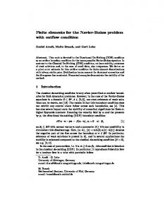
Example 2: flow around cylinder
This test problem is derived from a benchmark problem described in [13]. A mesh sample is shown in Figure 1. The inflow and outflow conditions (on left/right boundaries) is u1 = u1 =
0.3 × 4y(0.41 − y), u2 = 0 0.412 0.3 × 4y(0.41 − y), u2 = 0 0.412
on Γin = {0} × (0, 0.41), on Γout = {2.2} × (0, 0.41).
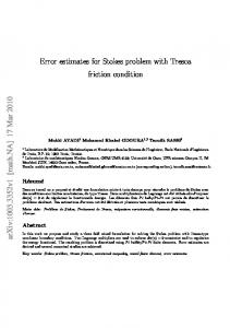
On the other parts of the boundary of Ω, homogeneous boundary conditions are precribed (i.e. u = 0). The parameter α in (2.1) is set to 0. The center of the cylinder is (0.25, 0.2) and the diameter is 0.1. The kinematic viscosity is ν = 10 −3 . This gives a Reynolds number of Re = 30 based on the diameter of the cylinder and the maximum of the inflow velocity. The domain is discretized by a non uniform mesh consisting of 1730 nodes and 3280 triangles, Figure 1. Isobar lines and streamlines are shown in Figures 2-3. The solution is obtained using the GMRES method (Matlab function gmres) after 2 iterations. The preconditioner is obtained by incomplete LU factorization. To reduce fill-in during factorization, we use the Matlab function symrcm to permute columns and rows. The complete program for this example is given in Annex A.2.
0.41
0
0
0.2
Figure 1: Geometry and boundary conditions of the flow around cylinder problem
2.2
7
CONCLUSION
16
Figure 2: Isobar lines for the flow around cylinder problem
Figure 3: Streamlines for the flow around cylinder problem
7
Conclusion
We have demonstrated that, for solving the Stokes problem in Matlab with the minielement, the vectorized code is much more efficient than a standard implementation with a loop over triangles. Further work is underway to derive vectorized codes, with the minielement, for solving 3D Stokes problems and more general fluid problems (Oseen equation, Navier-Stokes equations, etc).
References [1] Alberty J., Carstensen C. and Funken S.A. Remarks around 50 lines of matlab: short finite element implementation. Numer. Algorithms, 20:117–137, 1999. [2] Alberty J., Carstensen C., Funken S.A. and Klose R. Matlab implementation of the finite element method in elasticity. Computing, 69:239–263, 2002. [3] Arnold D., Brezzi F. and Fortin M. A stable finite element for the Stokes equations. Calcolo, 21:337–344, 1984. [4] Babuska I. Error bounds for finite element method. Numer. Math., 16:322–333, 1971. [5] Brezzi F. On the existence, uniqueness and approximation of saddle-point problems arising from Lagrange multipliers. RAIRO, 8:129–151, 1974. [6] Ern A. and Guermond J.-L. El´ements finis: th´eorie, applications, mise en œuvre, volume 36 of SMAI Math´ematiques et Applications. Springer, 2002.
A
17
APPENDIX
[7] Glowinski R. Numerical methods for fluids (part 3). In Ciarlet P.G. and Lions J.L., editors, Numerical Methods for Fluids (Part 3), volume IX of Handbook of Numerical Analysis, pages 3–1074. North-Holland, Amsterdam, 2003. [8] Glowinski R. and Le Tallec P. Augmented Lagrangian and Operator-splitting Methods in Nonlinear Mechanics. Studies in Applied Mathematics. SIAM, Philadelphia, 1989. [9] Koko J. Vectorized Matlab codes for two-dimensional linear elasticity. Scientific Programming, 2007. To appear. [10] Kwon Y.W. and Bang H. The Finite Element Method Using MATLAB. CRC Press, New York, 2000. [11] Persson P.-O. and Strang G. A simple mesh generator in Matlab. SIAM Rev., 42:329–345, 2004. [12] Pironneau O. Finite Elements for Fluids. Wiley, 1989. ¨ fer M. and Turek S. Benchmark computations of laminar flow around a [13] Scha cylinder. Notes Numer. Fluid Mech., 52:547–566, 1996.
A A.1
Appendix Main program for example 1
%-----------------------------------------------% Two-Dimensional Stokes Problem : P1-Bubble/P1 % Example 1 %------------------------------------------------% Constants alpha=1; nu=1; Pen=10^10; % Mesh load stkscarre289 %load stkscarre1089 %load stkscarre4225 %load stkscarre16641 %load stkscarre66049
xy xy xy xy xy
th th th th th
ibc1 ibc1 ibc1 ibc1 ibc1
ibc2 ibc2 ibc2 ibc2 ibc2
np=size(xy,1); nt=size(th,1); fprintf(’Mesh : np=%4d nt=%4d \n’,np,nt) % exact solution and source terms x=xy(:,1); y=xy(:,2); pi2=2*pi; pe=pi2*(cos(pi2*y)-cos(pi2*x)); u1e=-cos(pi2*x).*sin(pi2*y)+sin(pi2*y);
A
APPENDIX
u2e= sin(pi2*x).*cos(pi2*y)-sin(pi2*x); f1=alpha*u1e-nu*pi2*pi2*sin(pi2*y).*(2*cos(pi2*x)-1)+pi2*pi2*sin(pi2*x); f2=alpha*u2e+nu*pi2*pi2*sin(pi2*x).*(2*cos(pi2*y)-1)-pi2*pi2*sin(pi2*y); % Matrix and right-hand side A=stok2dp1bmat(xy,th,alpha,nu); b=stok2dp1brhs(xy,th,alpha,nu,f1,f2); % Boundary conditions A(ibc1,ibc1) =A(ibc1,ibc1)+Pen*speye(length(ibc1)); A(np+ibc2,np+ibc2)=A(np+ibc2,np+ibc2)+Pen*speye(length(ibc2)); b(ibc1)=0; b(np+ibc2)=0; A(2*np+1,2*np+1)=Pen; b(2*np+1)=0; % Solution by Gaussian elimination u=A\b; u1=u(1:np); u2=u(np+1:2*np); p=u(2*np+1:3*np); % Computing the bubble %[u1b,u2b]=stok2dp1bub(xy,th,alpha,nu,f1,f2,u1,u2,p);
A.2
Main program for example 2
%-----------------------------------------------% Two-Dimensional Stokes Problem : P1-Bubble/P1 % Example 2 %------------------------------------------------% Constants alpha=0; nu=10^-3; % Mesh load cylinder2d1730 xy th ibc1e ibc1i ibc2 np=size(xy,1); nt=size(th,1); ibc1=union(ibc1e,ibc1i); fprintf(’Mesh : np=%4d nt=%4d \n’,np,nt) % Matrix and right hand side A=stok2dp1bmat(xy,th,alpha,nu); A(2*np+1:3*np,2*np+1:3*np)=A(2*np+1:3*np,2*np+1:3*np)+10^-10*speye(np); b=zeros(3*np,1); % Boundary conditions A(ibc1,:)=0; A(ibc1,ibc1)=speye(length(ibc1)); A(np+ibc2,:)=0; A(np+ibc2,np+ibc2)=speye(length(ibc2)); b(ibc1)=0; b(ibc1e)=0.3*4*xy(ibc1e,2).*(0.41-xy(ibc1e,2))/(0.41^2); % columns and rows permutation k=symrcm(A);
18
A
APPENDIX
% Incomplete LU factorization [Li,Ui]=luinc(A(k,k),10^-4); % solve the linear system by GMRES method uu=rand(3*np,1); [uu(k),flag,res,iter]=gmres(A(k,k),b(k),8,10^-12,50,Li,Ui,uu(k)); if (flag ~= 0) fprintf(’GMRES:no convergence %15.8e \n’,norm(A*uu-b)) return else fprintf(’GMRES:convergence iter=%5d \n’,iter(1)) end uu=A\b; u1=uu(1:np); u2=uu(np+1:2*np); p=uu(2*np+1:3*np);
19