International Journal of Multimedia and Ubiquitous Engineering Vol.11, No.12 (2016), pp.383-400 http://dx.doi.org/10.14257/ijmue.2016.11.12.35
Vehicle License Plate Image Segmentation System Using Cellular Neural Network Optimized by Adaptive Fuzzy and Neuro-Fuzzy Algorithms Basuki Rahmat1,2, Endra Joelianto3, I Ketut Eddy Purnama1 and Mauridhi Hery Purnomo1 1
O m nl ad in e eV by e th rsio is n fil O e is nly IL . LE G
AL .
Department of Electrical Engineering, Faculty of Industrial Technology, Institut Teknologi Sepuluh Nopember, Surabaya 60111, Indonesia 2 Department of Informatics Engineering, Faculty of Industrial Technology, Universitas Pembangunan Nasional Veteran Jawa Timur, Surabaya 60294, Indonesia 3 Instrumentation and Control Research Group, Faculty of Industrial Technology, Institut Teknologi Bandung, Bandung 40132, Indonesia
[email protected],
[email protected],
[email protected],
[email protected],
[email protected] Abstract
ok
Vehicle License Plate Images Segmentation is a substantial stage for developing an Automatic License Plate Recognition (ALPR) system. In this paper, it is considered an efficient segmentation algorithm for extracting vehicle license plate images using Cellular Neural Networks (CNN). The learning CNN templates values are formulated as an optimization problem to achieve the desired performances which can be found by means of Adaptive Fuzzy (AF) algorithm and Neuro-Fuzzy (NF) algorithm techniques. The main objective of the paper is to compare the performances of standard CNN, Adaptive Fuzzy (AF), and Neuro-Fuzzy (NF) on real data of several vehicle license plate images of standard Indonesia License Plates. The results are then compared with ideal vehicle license plate images. Quantitative analysis between ideal vehicle license plate images and segmented vehicle license plate images is presented in terms of Peak signal-to-noise ratio (PSNR), Mean Squared Error (MSE) and Root Mean Squared Error (RMSE). From the performance analysis, the CNN template optimized by ANFIS algorithm is more recommended than the standard CNN edge detector or the CNN template optimized by Adaptive Fuzzy algorithm in vehicle license plate image segmentation. It is shown from the calculation that PSNR is 80% better than the standard CNN, and the resulted MSE and RMSE are 70% better than the standard CNN. Whereas the CNN template optimized by Adaptive Fuzzy algorithm achieves the PSNR 90% better than the standard CNN, but it yields the MSE and RMSE 40% worse than the standard CNN.
Bo
Keywords: ALPR; Cellular Neural Networks; Adaptive Fuzzy; Neuro-Fuzzy; ANFIS
1. Introduction
Vehicle license plate detection and recognition systems are widely known as Automatic License Plate Recognition (ALPR) [1], Automatic Vehicle Identification (AVI) [2], Car Plate Recognition (CPR) [3], Automatic Number Plate Recognition (ANPR) [4], and Optical Character Recognition (OCR) for car [5]. Many applications as well as related research have utilized the results of the vehicle's license plate detection and recognition system, such as automatic toll payment systems, intelligent transportation systems, intelligent parking system, intelligent traffic management system, vehicle security systems, vehicle accident prevention systems, automatic vehicle guidance
ISSN: 1975-0080 IJMUE Copyright ⓒ 2016 SERSC
International Journal of Multimedia and Ubiquitous Engineering Vol.11, No.12 (2016)
O m nl ad in e eV by e th rsio is n fil O e is nly IL . LE G
AL .
systems, traffic violations monitoring system, tracking systems and suspicious vehicle license plate recognition based on cameras reading installed in each intersection highway, and others. General approaches applied for vehicle license plate detection and recognition systems typically use vision-based techniques of image or video. In any cases, with respect to many issues of vehicle license plates include color, size, orientation, shape and pose vehicle license plates, the development of automatic, robust and effective vehicle license plate detection and recognition systems become a big challenge. The variety of license plate of various countries also causes the methods of vehicle license plate detection and recognition cannot be used universally. Generally, each country has a license plate with methods of license plate detection and recognition itself which is specific and distinctive. Plate detection and recognition systems of vehicle licenses consist of five stages: obtaining a vehicle license plate image (image acquisition), Extraction of License Plate, Segmentation of License Plate, Filtering of License Plate and Recognition of License Plate. The process of the stages is shown in Figure 1.
Image Acquisition
License Plate Extraction
License Plate Segmentation
License Plate Filtering
Character Recognition
L 1869 CI
Figure 1. Five Stages of an ALPR System
Bo
ok
The first stage is to obtain images using a camera. Camera parameters, such as type, resolution, shutter speed, orientation, and light should be considered as the influence to the quality of the images. The second stage is to extract the plate of the image based on some features, such as borders, color, or their characters. The third stage is the segmentation plate and extraction character by projecting their color information, labeling, or their position with the template matching. Further filtering is required for removing image noises. The final stage is to identify the extracted characters with the matching template or using the classification and the pattern recognition techniques. This paper only limits on the vehicle license plate segmentation process. The well-known method used in this vehicle license plate segmentation system is Cellular Neural Network (CNN). From several references, the CNN has been successfully used for image segmentation by using differential evolution algorithm [6] and by means of a genetic algorithm [7]. In [7], it has been shown that the genetic algorithm for template optimization of the CNN results in better performances compared to the simulated annealing algorithm [8]. Hence, for applications of the CNN, the selected algorithm influences the produced performance of the CNN. In computational intelligence, there are heuristic algorithms, such as in fuzzy systems, neural networks, and evolutionary computation, known as swarm intelligence, fractals and chaos theory, artificial immune systems, etc that might be used to optimize the CNN. To overcome the drawbacks of the previous research, we propose a new approach that utilize fuzzy algorithms for template CNN optimization, i.e. Adaptive Fuzzy algorithm and Neuro-Fuzzy algorithm [14],[15] in order to acquire a high-performance vehicle license plate segmentation system. Fuzzy logic has been widely utilized in identification, estimation, prediction and control, to illustrate [9]–[11]. Fuzzy logic is able to be added or modified for performance improvement [9]–[11]. On the other hand, Fuzzy logic is also
384
Copyright ⓒ 2016 SERSC
International Journal of Multimedia and Ubiquitous Engineering Vol.11, No.12 (2016)
easily mixed with other algorithms or methods in order to achieve better performances [12,13].
2. Proposed Methodology
Bo
ok
O m nl ad in e eV by e th rsio is n fil O e is nly IL . LE G
AL .
In this paper, the CNN will be implemented as a license plate image segmentation processor engine by detecting the edges of the letters and numbers shown in the vehicle number plate image. The block diagram of the proposed vehicle license plate segmentation is shown in Figure 2. Once the license plate image is given as an input to the network, the control template is directed to each pixel of the image and the adjusted image acts as an input to the CNN. The input image has the gray level value in the range [0 255]. The value is then scaled to a range [-1 1] as the CNN only works with a range of gray level values in the computation. The modified values in the image depend entirely in the neighborhood of each pixel, thus providing enhanced results. After the first iteration produces the output, the feedback template is utilized to the output and the resulted image is fed back to the CNN. This process is then repeated for several iterations until the network converges to a constant output. The segmented license plate cells are then attained as the output of the CNN. In order to result in better segmentation, the CNN template is then optimized by using Adaptive Fuzzy and Neuro-Fuzzy algorithms. Firstly, it is performed the CNN segmentation process by using a standard template. After that, the segmentation process is accomplished, in which, the CNN template is optimized by using Adaptive Fuzzy algorithm. The results of the segmentation process are compared to the standard CNN. Alternatively, the segmentation process of the CNN template is optimized by using the Neuro-Fuzzy algorithm. The results of the segmentation process are then compared to the standard CNN. Finally, the three results from the standard CNN, the CNN with Adaptive Fuzzy and the CNN with Neuro Fuzzy are compared in order to evaluate the performance of the presented methods applied to the segmentation of vehicle license plates. The algorithm steps depicting the proposed methodology are given below, (1) License Plate image and ideal license plate image are assigned as input images to the CNN. (2) The template values for the CNN are optimized by means of the standard CNN template. (3) The CNN is now carried out to run with input license plate images from step 1 and the template values from step 2. (4) The output of step 3 as the segmented vehicle license plate image is recorded. (5) Again new template values are optimized using Adaptive Fuzzy algorithm. (6) The CNN is carried out to run with the same input image as in step 1, but with new template values which are being obtained from step 5. (7) The output of step 6 as segmented vehicle license plate image is again recorded. (8) Again new template values are optimized with the Neuro-Fuzzy algorithm. (9) The CNN is carried out to run with the same input image as in step 1, but with new template values which are being obtained from step 8. (10) The output of step 9 as segmented vehicle license plate image is again recorded. (11) An evaluation is performed between the results obtained from steps 4, 7 and 10.
Copyright ⓒ 2016 SERSC
385
International Journal of Multimedia and Ubiquitous Engineering Vol.11, No.12 (2016)
Input Vehicle License Plate Images
Cellular Neural Networks
Standard CNN Template
CNN Template Optimization using Neuro-Fuzzy Algorithm
AL .
CNN Template Optimization using Adaptive Fuzzy Algorithm
Segmented Vehicle License Plate Images
O m nl ad in e eV by e th rsio is n fil O e is nly IL . LE G
Figure 2. Block Diagram of Proposed Methodology
The block diagram of the proposed methodology is shown in Figure 3. The CNN template optimized by the standard CNN template, the Adaptive Fuzzy, and the NeuroFuzzy algorithms to perform the vehicle license plate image segmentation process is shown in Figure 3. Original Input License Plate Image
Ideal Edge License Plate Image
Ideal Edge Detector
Standard
Adaptive Fuzzy Algorithm
Learning Error
+
Ʃ
-
Neuro-Fuzzy Algorithm
CNN
ok
Figure 3. The CNN Template Optimized by Standard CNN Template, Adaptive Fuzzy, and Neuro-Fuzzy Algorithms
Bo
3. Cellular Neural Network (CNN)
Cellular Neural Network (CNN) is a massive parallel computing paradigm defined in an n-dimensional regular array of elements, cells [16]. CNN can be defined as an array of 2D or 3D is locally connected to the nonlinear dynamic systems called cells, whose dynamics are functionally determined by a small group of parameters that controls cell interconnection strength [16]. The architecture of CNN, to illustrate [7], is depicted in the following block diagram as shown in Figure 4.
386
Copyright ⓒ 2016 SERSC
International Journal of Multimedia and Ubiquitous Engineering Vol.11, No.12 (2016)
Control Template
Bias + +
Local Input
Ʃ +
Internal State
-
f (.)
Output
d dt
Input from Neighborhood
AL .
Feedback Template
O m nl ad in e eV by e th rsio is n fil O e is nly IL . LE G
Feedback from Neighborhood
Figure 4. CNN Block Diagram
A class 1 MxN standard CNN is defined by a MxN rectangular array of cells C (i, j )
located at the site (i, j ) , i 1,2,, M , j 1,2,, N . Each cell C (i, j ) is defined mathematically, by following [17], in state equation as follows:
xij xij
where
xij R
,
A i, j; k , l y
C k ,l S r i , j
ykl R u kl R ,
, and
kl
B i, j; k , l u
C k ,l S r i , j
zij R
kl
zij
(1)
are called state, output, input, and
threshold of cell C (i, j ) , respectively. A(i, j; k , l ) and B(i, j; k , l ) are called the feedback and the input synaptic operators (or feedback template and control template). The index pair (i, j; k , l ) denotes the signal direction from the cell C (i, j ) to the cell
C (k , l ) . The output equation is given by the equation yij f xij
1 1 xij 1 xij 1 2 2
(2) From the block diagram CNN in Figure 4, there are two (2) important matrices. There
Bo
ok
are the matrix A(i, j; k , l ) and B(i, j; k , l ) called feedback template and control template respectively. Sometimes, the values of the elements of the matrix are chosen as an arbitrary value [18]. For example, if the matrix is selected to the size of 3x3 matrix, then the values of the elements of the two matrices are:
a1 a 2 a3 b1 b2 b3 A a 4 a5 a6, B b4 b5 b6 a7 a8 a9 b7 b8 b9 where the value of the elements a1,, a9 , and b1,, b9 is an arbitrary value.
(3)
In other references, the values of the elements of the matrix A(i, j; k , l ) and
B(i, j; k , l ) are arranged in the form of cloning template [6]-[7]. The brief explanation is as follows. To illustrate for a 3x3 matrix, the value of each element of the matrix corresponds to the following equations according to [6]:
Copyright ⓒ 2016 SERSC
387
International Journal of Multimedia and Ubiquitous Engineering Vol.11, No.12 (2016)
A i, j; k , l A k , l; i, B i, j; k , l B k , l; i,
j , j
xij 0 1, uij 1 (4)
A fully stable CNN can be formed by selecting the following cloning template [6]:
a1 a9 , a2 a8 , a3 a7 , a4 a6 , b1 b9 , b2 b8 , b3 b7 , b4 b6 .
(5)
And the feedback template and control template matrix are as follow:
a1 a 2 a3 a1 a 2 a3 A a 4 a5 a6 a 4 a5 a 4 a7 a8 a9 a3 a 2 a1
AL .
O m nl ad in e eV by e th rsio is n fil O e is nly IL . LE G
b1 b2 b3 b1 b2 b3 B b4 b5 b6 b4 b5 b4 b7 b8 b9 b3 b2 b1
(6)
(7) For the standard CNN template, in this paper, the values are selected by trial and random, repeated such that the selected values lead to the best results.
4. Adaptive Fuzzy (AF) Based Template Optimization
In this part, the CNN is combined with Adaptive Fuzzy. Adaptive Fuzzy usually expressed in the form of changes in the Fuzzy Membership Function. Examples of changes Gaussian-type Membership Function can be found at [19]. The Adaptive Fuzzy (AF) algorithm is used to process template tuning CNN in order to obtain the parameter values of A and B as the feedback template and the control template. To get the CNN template values, the matrix A and B are in the standard form as follow:
a1 a 2 a3 A a 4 a5 a6 , a7 a8 a9
b1 b2 b3 B b4 b5 b6 b7 b8 b9
Bo
ok
(8) where the values of the feedback template and the control template are optimized by means of Adaptive Fuzzy Membership Functions (MF) as shown in Figure 5.
388
Copyright ⓒ 2016 SERSC
International Journal of Multimedia and Ubiquitous Engineering Vol.11, No.12 (2016)
µ 1
SE
BE
ME
error (a) SDE
BDE
MDE
O m nl ad in e eV by e th rsio is n fil O e is nly IL . LE G
AL .
µ 1
delta error (b)
Figure 5. (a) Membership Function of Error. (b) Membership Function of Delta Error By using the following terms: small error (SE), medium error (ME), big error (BE), small delta error (SDE), medium delta error (MDE) and big delta error (BDE), the wellknown bell function is used as the membership function. The bell functions are given by the following equations:
SDE bell (delta error; b1, b2, b3) MDE bell (delta error; b4, b5, b6) BDE bell (delta error; b7, b8, b9) (9) a ,b ,c The formulation of Bell with the membership function parameters i i i and x as SE bell (error; a1, a2, a3) ME bell (error; a4, a5, a6) BE bell (error; a7, a8, a9)
error or delta error is given by the following equation:
bell ( x; ai , bi , ci )
1
2bi x ci 1 a i
Bo
ok
(10) To get a wide variety of Fuzzy MF which means a variation of CNN template, the process is carried out by using the following iterative procedure as shown in Figure 6.
Copyright ⓒ 2016 SERSC
389
International Journal of Multimedia and Ubiquitous Engineering Vol.11, No.12 (2016)
New Fuzzy MF as n Templates Template selection process for i, i=1 to n Input Image
AL .
Template i
O m nl ad in e eV by e th rsio is n fil O e is nly IL . LE G
CNN
Resulting Image
-
Target Image
Ʃ
+
Error and Delta Error
Figure 6. CNN Template Creation Process Using Adaptive Fuzzy MF
Bo
ok
The CNN output is compared with the target image which is regarded as a desired ideal plate. From this comparison, it is obtained the difference (error). Error and delta error are then used as the adaptive fuzzy membership function defined as New CNN Template variance. Furthermore, the CNN output is compared to the target image and gives the difference (error) again. The process is repeated continuously until the RMSE achieves the accepted level or the iteration is terminated. The variations of Fuzzy MF parameters as the new CNN template of A and B as feedback template and control template variances are defined by using the following equations.
390
Copyright ⓒ 2016 SERSC
International Journal of Multimedia and Ubiquitous Engineering Vol.11, No.12 (2016)
a1(i) error (i ) A(i 1) a 4(i ) error (i ) a7(i ) error (i )
a 2(i ) a5(i ) a8(i )
b1(i ) delta error (i ) B(i 1) b4(i ) delta error (i ) b7(i ) delta error (i )
a3(i ) error (i ) a 6(i ) error (i ) a9(i ) error (i ) b3(i ) delta error (i ) b6(i ) delta error (i ) b9(i ) delta error (i )
b2(i ) b5(i ) b8(i )
(11)
O m nl ad in e eV by e th rsio is n fil O e is nly IL . LE G
AL .
where error and delta error denote the average error and the average delta error respectively and i as the iteration step. To get the best MF parameters which are the best CNN template, it can be done by repeating the experiment several times. After that, the best parameters that meet the criteria are selected. Alternatively, during the process, it is observed the alteration of the parameters by using rules of convergence error defined as the root mean square error (RMSE). The convergence of error is defined by the equation:
P , Pi 1 new Pold ,
where
if RMSE ( Pi 1 ) RMSE ( Pi ), otherwise.
(12)
Pi represents the MF parameters of Bell, i.e. ai , bi , ci and ( i denotes iteration). Pi 1 Pold Pi 1 Pi
Pnew as the new variance of
and
as
.
5. Neuro-Fuzzy (NF) Based Template Optimization
ok
In this part, the CNN is mixed together with Neuro-Fuzzy. The Neuro-Fuzzy (NF) algorithm is utilized to process template tuning CNN. The Neuro-Fuzzy used to optimize the CNN template is Adaptive-Network-Based Fuzzy Inference System or Adaptive Neuro-Fuzzy Inference System (ANFIS) described in [14]-[15]. In this process, ANFIS is implemented in order to find the value of A and B defined as the feedback template and the control template. The CNN template values are acquired by using the standard matrix A and B as described in the equation (8) similar to the representation used in the Adaptive Fuzzy algorithm:
a1 a 2 a3 A a 4 a5 a6 , a7 a8 a9
b1 b2 b3 B b4 b5 b6 b7 b8 b9
Bo
To get a wide variety of ANFIS MF which means a variation of CNN template, the process is shown in Figure 7. The process is similar to the Adaptive Fuzzy optimization with an addition in the Forward Pass process of ANFIS.
Copyright ⓒ 2016 SERSC
391
International Journal of Multimedia and Ubiquitous Engineering Vol.11, No.12 (2016)
Error and Delta Error
New ANFIS MF as n Templates Template selection process for i, i=1 to n
+ Template i
Input Image
Ʃ
O m nl ad in e eV by e th rsio is n fil O e is nly IL . LE G
CNN
Forward Pass ANFIS
AL .
-
Resulting Image
-
Target Image
Ʃ
+
Error and Delta Error
Figure 7. CNN Template Creation Process Using ANFIS MF
A1 bell ( x; a1, a2, a3) A2 bell ( x; a4, a5, a6) A3 bell ( x; a7, a8, a9)
B1 bell ( y; b1, b2, b3) B2 bell ( y; b4, b5, b6) B3 bell ( y; b7, b8, b9)
(13)
Bo
ok
Error and delta error are defined as inputs to Forward Pass of the ANFIS structure as shown in Figure 8. The steps of the Neuro-Fuzzy algorithm to process template tuning of the CNN by using Forward Pass of ANFIS are described as follow. Layer 1: In this layer, the bell function is utilized as the membership functions which are given by the following equations:
392
Copyright ⓒ 2016 SERSC
International Journal of Multimedia and Ubiquitous Engineering Vol.11, No.12 (2016)
Layer 1 Layer 4
A1 Layer 3
Layer 2
x y
Target Image
x (Error)
w1
π +
N
Layer 5
w1
w1 f1 +
A3
w2
N
w2
B1
-
x π
y (Delta Error)
w2 f2
w3
N
f
Ʃ
(Output)
y
w3
Ʃ
error and delta error
w3 f3
B2 x y
O m nl ad in e eV by e th rsio is n fil O e is nly IL . LE G
B3
New ANFIS MF as n Templates
AL .
π
Ʃ
Resulting Image of CNN
Target Image
A2
Figure 8. Neuro-Fuzzy Structure
Layer 2: In this layer, fuzzy logic AND is used in the node function. The outputs of this layer follow the equations:
w1 min ( A1 , B1 )
w2 min ( A2 , B2 ) w3 min ( A3 , B3 )
(14)
Layer 3: The input signals of this layer are normalized, the normalization is given by:
w1 w1 w2 w3 w2 w2 w1 w2 w3 w3 w3 w1 w2 w3 w1
(15)
Layer 4: Arranging the incoming signals, it is obtained a matrix M which is of the form:
M [(w1 x) (w1 y) w1 ( w2 x) (w2 y) w2 (w3 x) (w3 y) w3 ]
ok
(16) By means of the Least Square Estimate (LSE) method, the consequent parameters
Bo
[1 ...9 ] are found by using the following equation: [M T M ]1 M T D
(17)
where D is the desired output of the neuro-fuzzy (ANFIS). The consequent parameters [1 ...9 ] f3 f1 f 2 are then used to compute
,
and
by using the following equations:
f1 1 x 2 y 3
f 2 4 x 5 y 6 f 3 7 x 8 y 9
Copyright ⓒ 2016 SERSC
(18)
393
International Journal of Multimedia and Ubiquitous Engineering Vol.11, No.12 (2016)
After that, the outputs of nodes in layer 4 are obtained by computing w1 f1 , w2 f 2 and
w3 f 3 . Layer 5: Finally, the outputs of this layer become the ANFIS output which is the summation of the input signals given by
f w1 f1 w2 f 2 w3 f 3
O m nl ad in e eV by e th rsio is n fil O e is nly IL . LE G
AL .
(19) The next process is to compare the output of the ANFIS with the target image regarded as a desired ideal plate. From this comparison, it is obtained the difference (error). The error and the delta error are then used as ANFIS MF performed as New CNN Template variance. Furthermore, the CNN output is then compared to the target image and produced the difference (error) again. Error and Delta Error act as ANFIS inputs and then are processed by using Forward Pass of ANFIS to produce the ANFIS output. The ANFIS output is then compared with the target image to get the Error and Delta Error that are used as ANFIS MF as New CNN Template variance. The process is repeated continuously until the RMSE value is accepted or the iteration is terminated. The equation of ANFIS MF parameters variation as new CNN template is updated by using the same definition as Fuzzy MF parameters in equation (11). To get the best ANFIS MF parameter which is the best CNN template, it is carried out by repeating the experiment several times and the best parameters that meet the criteria are then selected. Alternatively, during the iteration process, it is observed the change of the parameters by using rules convergence error (RMSE) as given in equation (12) where error and delta error are the average error and the average delta error respectively obtained after the Forward Pass process of ANFIS compared to the target image.
6. Results and Discussion
The proposed methods are tested to the Indonesia Standard license plate images segmentation. The results of the segmentation process are close to the ideal target vehicle license plate images. The ideal vehicle license plate images which are targeted as shown in Figure 11, are the result of the license plate images which have been cleaned from the noise or unwanted information manually. Trials have been performed several times to process Indonesia vehicle license plate images. The optimized template values, A and B templates as feedback and control templates and bias ( I ) are given in Table 1.: Table 1. The Optimized Template Values
Bo
ok
Fuzzy based optimized template
394
ANFIS based optimized template
8.11 2.50 42.25 A 8.11 2.50 3.53 8.11 2.50 121.47
50.00 2.50 0.01 A 50.00 2.50 125.00 50.00 2.50 250.00
118.54 2.50 84.41 B 118.54 2.50 43.54 118.54 2.50 5.18 I0
229.90 2.50 232.64 B 229.90 2.50 249.12 229.90 2.50 251.26 I0
Copyright ⓒ 2016 SERSC
International Journal of Multimedia and Ubiquitous Engineering Vol.11, No.12 (2016)
O m nl ad in e eV by e th rsio is n fil O e is nly IL . LE G
AL .
The initial and the final Fuzzy MF obtained by using Adaptive Fuzzy algorithm as the function of error and delta error before and after the optimization process are shown in Figure 9. For ANFIS, the initial and the final ANFIS MF changes are shown in Figure 10.
Figure 9. Initial Membership Function and Final membership Function of Error and Delta Error for Adaptive Fuzzy
Figure 10. Initial Membership Function and Final Membership Function of Error and Delta Error for ANFIS
Bo
ok
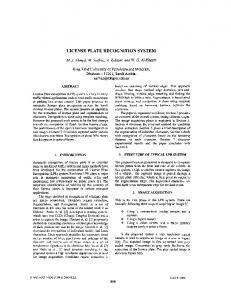
The results of several experiments using different license plate images are shown in Figure 11. Three image quality measurements, such as Peak signal-to-noise ratio (PSNR), Mean Squared Error (MSE) and Root Mean Squared Error (RMSE) are utilized to measure the difference between two images. The calculation results using PSNR, MSE, and RMSE image quality measurements are shown in Table 2. To calculate the MSE and PSNR, the following equations are used [20].
1 M N MSE X ij X ij MN i 1 j 1 PSNR 10 . log10
J2 dB MSE
2
(20)
where:
X ij
th th is the i row and the j column pixel in the target image,
Copyright ⓒ 2016 SERSC
395
International Journal of Multimedia and Ubiquitous Engineering Vol.11, No.12 (2016)
X ij
th
is the i row and the j column pixel in the segmented image, M and N are the height and the width of the image, J is the dynamic range of pixel values, or the maximum value that a pixel can take (equals to (255) for 8-bit images). In the experiment, the expected results are small values for MSE and RMSE and big value for PSNR. This means the difference between pixels in the target area is close to zero. As can be seen from Table 2, the CNN template optimized by Adaptive Fuzzy algorithm results in the PSNR values are better than the standard CNN as indicated by the value of PSNR higher than the standard CNN on the license plates of vehicles to 1, 2, 3, 4, 5, 6, 7, 8, 10 (nine of ten or 90%). However, the MSE and RMSE values are smaller than the standard CNN on the license plates of vehicles to 2, 4, 6, 9 (four of ten or 40%). For the CNN template optimized by ANFIS algorithm, the PSNR values are better than the standard CNN as indicated by the value of PSNR higher than the standard CNN on the license plates of vehicles to 1, 2, 3, 4, 6, 7, 8, 10 (eight of ten or 80%). Moreover, the MSE and RMSE values are smaller than the standard CNN on the license plates of vehicles to 1, 3, 4, 5, 6, 9, 10 (seven of ten or 70%). Comparison with the standard CNN, the CNN template optimized by Adaptive Fuzzy algorithm or the CNN template optimized by ANFIS algorithm produced better performances than the standard CNN. Both CNN templates optimized by Adaptive Fuzzy or ANFIS algorithm had the advantages of each. The CNN template optimized by Adaptive Fuzzy algorithm contributed to the PSNR values better than optimized by ANFIS. While the CNN template optimized by ANFIS algorithm contributed to the MSE and the RMSE values better than optimized by Adaptive Fuzzy. To sum up, the CNN template optimized by ANFIS algorithm produced better image quality than the standard CNN and the CNN template optimized with Adaptive Fuzzy algorithm.
O m nl ad in e eV by e th rsio is n fil O e is nly IL . LE G
AL .
th
Input Image
Target Image
CNN
CNN+Fuzzy CNN+ANFIS
1.
2. 3. 4.
ok
5.
Bo
6.
7.
8. 8. 10. Figure 11. Segmentation Results
396
Copyright ⓒ 2016 SERSC
International Journal of Multimedia and Ubiquitous Engineering Vol.11, No.12 (2016)
Table 2. Image Quality Measurement
L 1869 CI L 1866 BK W 1270 XM W 500 NH B 1406 BZK B 1400 NLQ P 1034 QO N 1986 VH AG 5140 UE DK 1946 ET
PSNR 10.01 10.07 11.25 11.61 12.26 9.99 10.33 12.34 5.77 7.69
7. Conclusions
CNN MSE 191.25 186.48 207.34 215.87 208.94 200.54 189.97 221.06 111.27 153.15
RMSE 13.83 13.66 14.40 14.69 14.45 14.16 13.78 14.87 10.55 12.38
PSNR 10.13 10.25 11.74 11.72 12.39 10.07 10.67 12.45 5.77 7.86
CNN+Fuzzy MSE RMSE 193.01 13.89 186.16 13.64 207.91 14.42 214.59 14.65 210.82 14.52 199.36 14.12 193.42 13.91 223.08 14.94 110.21 10.50 153.87 12.40
CNN+ANFIS PSNR MSE RMSE 10.05 190.61 13.81 10.39 190.85 13.81 11.34 205.76 14.34 11.68 214.56 14.65 12.26 207.31 14.40 10.01 199.01 14.11 10.55 190.50 13.80 12.47 223.17 14.94 5.73 108.65 10.42 7.94 152.18 12.34
AL .
License Plate
O m nl ad in e eV by e th rsio is n fil O e is nly IL . LE G
The paper proposed Adaptive Fuzzy and Neuro-Fuzzy algorithms as a learning method in the CNN template for the vehicle license plate image segmentation. The quality of the vehicle license plate image segmentation was determined by using the calculation of PSNR, MSE, and RMSE respectively. Experiment results indicated that the CNN template optimized by Adaptive Fuzzy and ANFIS algorithm proposed in this paper are better than the standard CNN edge detector in vehicle license plate image segmentation. But the CNN template optimized by ANFIS algorithm is recommended. It is shown from the calculation of PSNR, the CNN template optimized by ANFIS algorithm is 80% better than the standard CNN, and the resulted MSE and RMSE are 70% better than the standard CNN. Whereas the CNN template optimized by Adaptive Fuzzy algorithm achieves the PSNR 90% better than the standard CNN, but it yields the MSE and RMSE 40% worse than the standard CNN. The results show that our new approach is able to acquire highperformance vehicle license plate image segmentation system.
Acknowledgements
The first author is grateful to the doctoral fellowship program funded by the Directorate General of Higher Education, Ministry of Research and Education, Indonesia.
References [1]
[2]
ok
[3]
S. Du, M. Ibrahim, M. Shehata, and W. Badawy, “Automatic License Plate Recognition (ALPR): A State-of-the-Art Review”, IEEE Trans. on Circuits Syst. Video Technol., vol. 23, no. 2, (2013), pp. 311– 325. J. J. V. Díaz, A. B. R. González, and M. R. Wilby, “Bluetooth Traffic Monitoring Systems for Travel Time Estimation on Freeways”, IEEE Trans. Intell. Transp. Syst., vol. 17, no. 1, (2016), pp. 123-132. D. Jiang, T. M. Mekonnen, T. E. Merkebu, and A. Gebrehiwot, “Car Plate Recognition System”, 2012 Fifth International Conference on Intelligent Networks and Intelligent Systems (ICINIS), (2012), pp. 912. S. Shaikh, B. Lahiri, G. Bhatt, and N. Raja, “A novel approach for automatic number plate recognition”, 2013 International Conference on Intelligent Systems and Signal Processing (ISSP), (2013), pp. 375– 380. V. Lukic, A. Makarov, and M. Spanovic, “An application of image point operators for OCR improvement in ALPR algorithm”, 2012 20th IEEE Telecommunications Forum (TELFOR), (2012), pp. 697–700. A. Baştürk and E. Günay, “Efficient edge detection in digital images using a cellular neural network optimized by differential evolution algorithm”, Expert Syst. Appl., vol. 36, no. 2, Part 2, (2009), pp. 2645 – 2650. D. Selvathi, H. Selvaraj, and S. T. Selvi, “Hybrid Approach For Brain Tumor Segmentation In Magnetic Resonance Images Using Cellular Neural Networks And Optimization Techniques”, Int. J. Comput. Intell. Appl., vol. 09, no. 01, (2010), pp. 17–31. B. Chandler, C. Rekeczky, and Y. Nishio, "Adaptive Simulated Annealing in CNN Template Learning", IEICE TRANS. on Fund. of Elect. Communications and Computer Sciences, vol. 82, no. 2, (1999), pp. 398-402.
Bo
[4]
[5]
[6]
[7]
[8]
Copyright ⓒ 2016 SERSC
397
International Journal of Multimedia and Ubiquitous Engineering Vol.11, No.12 (2016)
[11]
[12]
[13] [14] [15]
[16] [17] [18]
[19]
[20]
AL .
[10]
E. Joelianto and B. Rahmat, “Adaptive Neuro Fuzzy Inference System (ANFIS) with Error Backpropagation Algorithm using Mapping Function”, Int. J. Artif. Intell., vol. 1, no. A08, (2008), pp. 3–22. E. Joelianto, S. Widiyantoro, and M. Ichsan, “Time series estimation on earthquake events using ANFIS with mapping function”, Int. J. Artif. Intell., vol. 3, no. A09, (2008), pp. 37–63. E. Joelianto, D. C. Anura, and M. P. Priyanto, “ANFIS–hybrid reference control for improving transient response of controlled systems using PID controller”, Int. J. Artif. Intell., vol. 10, no. A13, (2013), pp. 88–111. R. E. Precup, M. C. Sabau, and E. M. Petriu, “Nature-inspired optimal tuning of input membership functions of Takagi-Sugeno-Kang fuzzy models for Anti-lock Braking Systems”, Appl. Soft Computing, vol. 27, (2015), pp. 575-589. S. Park, S. J. Lee, E. Weiss, and Y. Motai, “Intra- and Inter-Fractional Variation Prediction of Lung Tumors Using Fuzzy Deep Learning”, IEEE J. Transl. Eng. Health Med., vol. 4, (2016), pp. 1–12. J.-S. R. Jang, “ANFIS: adaptive-network-based fuzzy inference system”, IEEE Trans. On Syst. Man Cybern., vol. 23, no. 3, (1993), pp. 665 –685. A. Tjahjono, A. Priyadi, M. H. Purnomo, and M. Pujiantara, “Overcurrent relay curve modeling using adaptive neuro fuzzy inference system”, 2014 Int. Conference on Electrical Engineering and Informatics (MICEEI), Makassar, Indonesia, (2014), pp. 103–108. L. O. Chua and L. Yang, “Cellular neural networks: theory”, IEEE Trans. on Circuits Syst., vol. 35, no. 10, (1988), pp. 1257 –1272. L. O. Chua and T. Roska, “Cellular Neural Networks and Visual Computing: Foundations and Applications”, Cambridge University Press., (2004). A. Fasih, J. Chamberlain Chedjou, and K. Kyamakya, “Cellular Neural Networks-Based Genetic Algorithm for Optimizing the Behavior of an Unstructured Robot”, Int. J. Comput. Intell. Syst., vol. 2, no. 2, (2009), pp. 124–131. L. Xia and Y. Xiuju, “The Application of Adaptive Fuzzy Inference Model in the Nonlinear Dynamic System Identification”, Second International Conference on Intelligent Computation Technology and Automation (ICICTA’09), vol. 2, (2009), pp. 814–817. A. Almohammad and G. Ghinea, “Stego image quality and the reliability of PSNR”, 2010 2nd International Conference on Image Processing Theory Tools and Applications (IPTA), (2010), pp. 215– 220.
O m nl ad in e eV by e th rsio is n fil O e is nly IL . LE G
[9]
Authors
Bo
ok
Basuki Rahmat, He is a lecturer at bachelor degree in Universitas Pembangunan Nasional Veteran Jawa Timur. He received the bachelor degree in Instrumentation Physics from Institut Teknologi Sepuluh Nopember Surabaya in 1995. He received a master degree in Instrumentation and Control from Institut Teknologi Bandung, in 2000. Currently, he is a Ph.D. candidate in Electrical Engineering at Institut Teknologi Sepuluh Nopember, Surabaya. His research interests are an intelligent system, soft computing, image and video processing, intelligent control, MATLAB, PHP, Python and Delphi Programming.
398
Endra Joelianto, received the bachelor degree in Engineering Physics from Institut Teknologi Bandung (ITB), Indonesia in 1990. He received Ph.D. in Engineering, from The Australian National University (ANU), Australia in 2002. Currently, he is the staff of Instrumentation and Control Research Group, Faculty of Industrial Technology, Institut Teknologi Bandung (ITB), Indonesia and Research Professor at Centre for UnManned System Studies (CentrUMS), ITB, Indonesia. His research interests are Hybrid/Discrete Event Control Systems, Advanced Control, Embedded Control Systems and Intelligent Systems.
Copyright ⓒ 2016 SERSC
International Journal of Multimedia and Ubiquitous Engineering Vol.11, No.12 (2016)
I Ketut Eddy Purnama, received the bachelor degree in Electrical Engineering from Institut Teknologi Sepuluh Nopember (ITS), Surabaya, Indonesia in 1994. He received his Master of Technology from Institut Teknologi Bandung, Bandung, Indonesia in 1999. He received a Ph.D degree from University of Groningen, Netherlands in 2007. Currently, he is the staff of Electrical Engineering Department of Institut Teknologi Sepuluh Nopember, Surabaya, Indonesia. His research interests are Data Mining, Medical Image Processing, and Intelligent System.
Bo
ok
O m nl ad in e eV by e th rsio is n fil O e is nly IL . LE G
AL .
Mauridhi Hery Purnomo, received the bachelor degree from Institut Teknologi Sepuluh Nopember (ITS), Surabaya, Indonesia in 1985. He received his M.Eng., and Ph.D. degrees from Osaka City University, Osaka, Japan in 1995, and 1997, respectively. He has joined ITS in 1985 and has been a Professor since 2003. His current interests include intelligent system applications, image processing, medical imaging, control, and management. He is a Member of IEEE and INNS.
Copyright ⓒ 2016 SERSC
399
Bo
ok
O m nl ad in e eV by e th rsio is n fil O e is nly IL . LE G
AL .
International Journal of Multimedia and Ubiquitous Engineering Vol.11, No.12 (2016)
400
Copyright ⓒ 2016 SERSC