Verification of Architectural Refactoring Rules
D´enes Bisztray, Reiko Heckel, Hartmut Ehrig
Department of Computer Science, University of Leicester,
[email protected]
October 27, 2008
Abstract With the success of model-driven development as well as component-based and service-oriented systems, models of software architecture are key artefacts in the development process. To adapt to changing requirements and improve internal software quality such models have to evolve while preserving aspects of their behaviour. To avoid the costly verification of refactoring steps on large systems we present a method which allows us to extract a (usually much smaller) rule from the transformation performed and verify this rule instead. The main result of the paper shows that the verification of rules is indeed sufficient to guarantee the desired semantic relation between source and target models. We apply the approach to the refactoring of architectural models based on UML component, structure, and activity diagrams, with using CSP as a semantic domain.
Contents 1 Introduction
3
2 Related Work
6
3 Architectural Models 3.1 Type-Level . . . . 3.2 Instance-Level . . . 3.3 Behaviour . . . . . 3.4 Metamodel . . . .
. . . .
. . . .
. . . .
. . . .
. . . .
. . . .
. . . .
. . . .
. . . .
. . . .
. . . .
. . . .
. . . .
. . . .
. . . .
. . . .
. . . .
. . . .
. . . .
. . . .
. . . .
. . . .
. . . .
. . . .
8 8 9 10 11
4 Model Refactoring 13 4.1 Description of the Refactoring . . . . . . . . . . . . . . . . . . 13 4.2 Rule Extraction . . . . . . . . . . . . . . . . . . . . . . . . . . 14 5 Semantic Domain 5.1 Communicating Sequential 5.2 Representation in FDR2 . 5.3 Abstract Syntax . . . . . . 5.3.1 Concurrency . . . . 5.3.2 Renaming . . . . .
. . . . .
. . . . .
. . . . .
. . . . .
. . . . .
. . . . .
. . . . .
. . . . .
. . . . .
. . . . .
. . . . .
17 17 19 20 21 22
6 Semantic Mapping 6.1 Type-Level Mapping. . . . . . . . . . . . . . 6.1.1 Components . . . . . . . . . . . . . . 6.1.2 Ports . . . . . . . . . . . . . . . . . . 6.1.3 Interfaces . . . . . . . . . . . . . . . 6.2 Behavioural Mapping . . . . . . . . . . . . . 6.2.1 Initial Node, Action and Final Node 6.2.2 Communication Events . . . . . . . . 6.2.3 Decision Node and Merge Node . . . 6.2.4 Fork Node and Join Node . . . . . .
. . . . . . . . .
. . . . . . . . .
. . . . . . . . .
. . . . . . . . .
. . . . . . . . .
. . . . . . . . .
. . . . . . . . .
. . . . . . . . .
. . . . . . . . .
. . . . . . . . .
23 24 25 26 27 29 29 30 31 32
Processes. . . . . . . . . . . . . . . . . . . . . . . . .
1
. . . . .
. . . . .
. . . . .
6.3 Instance-Level Mapping. . . 6.3.1 Component Objects . 6.3.2 Channels . . . . . . . 6.4 Renaming Rules . . . . . . . 6.5 Application to the Rule . . .
. . . . .
. . . . .
. . . . .
. . . . .
. . . . .
. . . . .
. . . . .
. . . . .
. . . . .
. . . . .
. . . . .
. . . . .
. . . . .
. . . . .
. . . . .
. . . . .
. . . . .
. . . . .
. . . . .
34 34 34 35 37
7 Correctness of Rule-level Verification 38 7.1 Correctness . . . . . . . . . . . . . . . . . . . . . . . . . . . . 38 8 Compositionality. 42 8.1 Simple Graph Transformations . . . . . . . . . . . . . . . . . . 42 8.2 Graph Transformations with NACs . . . . . . . . . . . . . . . 44 9 Conclusion and Future Work
51
2
Chapter 1 Introduction Nothing endures but change, as the philosopher says [10]. As much as anywhere else, this applies to the world of software. In order to improve the internal structure, performance, or scalability of software systems, changes may be required that preserve the observable behaviour of systems. In OO programming, such behaviour-preserving transformations are known as refactorings [7]. Today, where applications tend to be distributed and serviceoriented, the most interesting changes take place at the architectural level. Even if these changes are structural, they have to take into account the behaviour encapsulated inside the components that are being replaced or reconnected. In analogy to the programming level we speak of architectural refactorings if preservation of observable behaviour is intended. In this paper, refactoring is addressed at the level of models. Given a transformation from a source to a target model we would like to be able to verify their relation. In order to make this precise we have to fix three ingredients: the modelling language used, its semantics, and the relation capturing our idea of behaviour preservation. Notice however that in the mathematical formulation of our approach, these parameters can be replaced by others, subject to certain requirements. For modelling language we use the UML, which provides the means to describe both structure (by component and static structure diagrams) and behaviour (by activity diagrams) of service-oriented systems [17]. The semantics of the relevant fragment of the UML is expressed
3
in a denotational style, using CSP [9] as semantic domain and defining the mapping from UML diagrams to CSP processes by means of graph transformation rules. As different UML diagrams are semantically overlapping, the mapping has to produce one single consistent semantic model [5]. The semantic relation of behaviour preservation can conveniently be expressed using one of the refinement and equivalence relations on CSP processes. Based on these (or analogue) ingredients, we can formalise the question by saying that a model transformation M1 → M2 is behaviour-preserving if sem(M1 ) R sem(M2 ) where sem represents the semantic mapping and R the desired relation on the semantic domain. However, the verification of relation R over sufficiently large M1 and M2 can be very costly, while the actual refactoring might only affect a relatively small fragment of the overall model. Hence, it would be advantageous if we could focus our verification on those parts of the model that have been changed, that is, verify the refactoring rules rather than the actual steps. This is indeed possible, as we show in this paper, if both semantic mapping sem and semantic relation R satisfy suitable compositionality properties. We satisfy these requirements by specifying the mapping sem by graph transformation rules of a certain format and choosing CSP refinements as semantic relations. However, model-level architectural refactorings are unlikely to be created directly from semantics-preserving rules. Such rule catalogues as exist focus on object-oriented systems and are effectively liftings to the model level of refactoring rules for OO programs. Rather, an engineer using a modelling tool performs a manual model transformation M1 → M2 from which a verifiable refactoring rule has to be extracted first. In this we follow the idea of model transformation by example [23] where model transformation rules expressed as graph transformations are derived from sample transformations. The paper is structured as follows. In Sect. 3 we present our architectural models along with an example, on which a refactoring step is performed in Sect. 4. Section 6 introduces CSP as the semantic domain and describes the mapping and the semantic relation. The formal justification for rule-level verification is discussed in Sect. 7. It is demonstrated that the method is sound if the semantic mapping is compositional, which is true based on a 4
general result which derives this property from the format of the mapping rules. Section 9 concludes the paper.
5
Chapter 2 Related Work After refactorings for Java were made popular by Fowler [7], several proposals for formalisation and verification based on first-order logics and invariants have been made [20, 13, 15]. The first formal approach to refactoring based on graph transformations is due to Mens [16], focusing on the analysis of conflicts and dependencies between rules. Refactoring of architectural models has been studied formally in architectural description languages (ADLs) like Wright [1] or Darwin [14], using process calculi like CSP or π-calculus for expressing formal semantics. Our semantic mapping to CSP follows that of [5] for UML-RT [19], an earlier component-based extension to the UML, but distinguishes type and instance level architectural models in UML 2. A number of authors have studied instance level architectural transformations, or reconfigurations. For example, Taentzer [21] introduces the notion of distributed graph transformation systems to allow architectural reconfiguration by means of two-level rules to express system-level and local transformations. The approach of [24] uses an algebraic framework to represent reconfigurations based on the coordination language Community. In [8] the architecture is represented by hypergraphs, where the hyperedges are the components, and the nodes are the communication ports. Architectural reconfigurations are represented by synchronised hyperedge replacement rules. Our approach combines the type level, typical of source code refactor-
6
ing, which happens at the level of classes, with the instance level typical of architectural transformations.
7
Chapter 3 Architectural Models This chapter presents our choice of architectural modelling language by means of an example based on the Car Accident Scenario from the SENSORIA Automotive Case Study [25]. We use UML component and composite structure diagrams for representing the type and instance-level architecture of our system in conjunction with activity diagrams specifying the workflows executed by component instances [17]. Briefly, the scenario is as follows. A car company is offering a service by which, in case one of the sensors in their car detects an accident, customers are contacted via their mobile phones to check if they require assistance. If they do, a nearby ambulance is dispatched. The system consists of three main parts: the agent in the car, the accident server, and the interface to the local emergency services. We present the architecture and behaviour of the accident server in detail.
3.1
Type-Level
Component diagrams specify the components, ports, interfaces that make up the building blocks of the system. Figure 3.1(a) shows the component diagram of the accident server. The AccidentManager is the core component, responsible for receiving
8
(a) Component Diagram
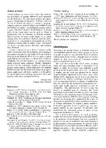
(b) faces
Inter-
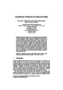
Figure 3.1: Architectural model of the accident server incoming alerts from cars through the AlertRecv port. In order to initiate a phone call it acquires the number of the driver from the PersistentDatabase, and passes it to the PhoneService, which calls the driver. In case the driver replies saying that assistance is not required, the alert is cancelled. Otherwise, the call is returned to the AccidentManager, which assesses the available data (including sensorial and location data from the car) and decides if the situation is a real emergency. In this case it passes the necessary data to the ServiceManager, which matches the GPS location of the car using the MapHandler, creates a service description, and contacts the serviceConnector interface that provides access to local emergency services. In the diagram, components are represented by rectangles with a component icon and classifier name. Smaller squares on the components represent the ports, provided interfaces are represented by circles and required interfaces by a socket shape [17]. Dashed arrows represent dependencies between the provided and required interfaces.
3.2
Instance-Level
The composite structure diagram specifying the configuration of the accident server is shown in Figure 3.2. Boxes named instance : type represent component instances. Ports are typed by interfaces defining the possible actions
9
that can happen through that port. For instance, the possible actions of the PhoneQuery port are defined by the phone interface. Links between port instances represent connectors, enabling communication between component instances [17].
Figure 3.2: Static Structure Diagram of the Accident Server
3.3
Behaviour
Figure 3.3: Activity Diagram of the AccidentManager component The behaviours of components are described by activity diagrams, like the one depicted in Figure 3.3 associated with the AccidentManager component. 10
Apart from the obvious control flow constructs they feature accept event actions, denoted by concave pentagons, that wait for the occurrence of specific events triggered by send signal actions, shown as convex pentagons [17]. They fit into the communication framework by representing functions calls from the corresponding interface through the relevant port. For instance, the phoneData send signal action in Fig. 3.3 represents the function call from phone interface through PhoneQuery port.
3.4
Metamodel
Formally, the UML models are instances of metamodels represented by attributed typed-graphs. The combined metamodel of the three diagrams is shown in Figure 3.4.
Figure 3.4: Metamodel for the Structure Model The reason for including the activity diagram and component diagram is the interconnection between the different nodes. Not only the component 11
is the container of activity nodes and edges, but also the ports are engaged with communication nodes. The component diagram is the metamodel of a composit structure diagram, thus it should be an abstraction level higher. However both are included in the same metamodel. Unfortunately there is no tool (and theoretical) support for graph transformations that spans more than two abstraction levels. Aside from the elements that have a self interpreting name, the component container contains all elements corresponding to one particular side of the refactoring rule. In the activity diagram part, the event node is a common parent for all nodes that represents an event. Communication node represents the special nodes that engage in communication through a port. On instance level, component object is the instance of a component, while the interaction point is the instance of a port. Connectable object is a similar base class on instance level as the connectable element. Channels are semantically not instances of owned interfaces, they are rather a realisation of them.
12
Chapter 4 Model Refactoring Continuing the description of the case study, a refactoring is presented in this chapter.
4.1
Description of the Refactoring
With the current architecture scalability issues may arise. Assuming that 70% of the incoming alerts are not real emergencies, the analysis of ’false alerts’ consumes considerable resources. The AccidentManager may thus turn out to be a bottleneck in the system. To address this scalability problem we extract the initial handling of alerts from the AccidentManager into an AlertListener component. The solution is depicted in Figure 4.1. The AlertListener receives alerts from cars, forwards them to the AccidentManager for processing while querying the database for the phone number and invoking the telephone service, which sends the results of its calls to the AccidentManager. The behaviour of the new AlertListener component is given in Figure 4.3(a), while the updated behaviour of the AccidentManager is shown in Figure 4.3(b).
13
(a) Component Diagram
(b) faces
Inter-
Figure 4.1: Architectural model of the refactored Accident Server
Figure 4.2: Configuration after the refactoring
4.2
Rule Extraction
However, rather than comparing the semantics of the entire system model before and after the change, we focus on the affected parts and their immediate context. More precisely, we are proposing to extract a model transformation rule which, (1) when applied to the source model produces the target model of the refactoring and (2) is semantics preserving in the sense that its lefthand side is in the desired semantic relation with its right-hand side. We will demonstrate in Sect. 7 that this is indeed sufficient to guarantee the corresponding relation between source and target model. In the example present, such a rule is shown in Fig. 4.4 for the structural part only. The behaviour transformation is given by the new and updated activity diagrams associated with the components in the rule. 14
(a) AlertListener
(b) AccidentManager
Figure 4.3: Owned behaviour after the refactoring
Figure 4.4: Refactoring rule The rule is applied by selecting in the source model an occurrence isomorphic to the left-hand side of the rule at both type and instance level. Thus, component C is matched by AccidentManager from Fig. 3.1(a), interface N corresponds to phone, M to processAlert, and J to phoneData. At instance level a similar correspondence is established. A rule is extracted as follows: G denotes the original model while H denotes the refactored one. The smallest consistent submodel of G containing G\H would form the left-hand side L of the rule, while the smallest submodel of H containing H \ G would form the right hand side R. In the algebraic approach to graph transformation, which provides the formal background of 15
this work, this is known as Initial Pushout Construction [4]. Recently a similar construction has been used as part of the model transformation by example approach, where a transformation specification is derived inductively from a set of sample transformation rules [23]. Notice that while the rule thus obtained is known to achieve the desired transformational effect, it is not in general guaranteed that the semantic relation between L and R can indeed be verified, even if it holds between G and H. The reason is that additional context information present in G and H may be required to ensure semantic compatibility. It is the responsibility of the modeller to include this additional context into the rule. However, as in the example presented, a minimal rule might not be enough because some additional context may have to be taken into account in order to guarantee the preservation of the semantics. In the example this has led to the introduction into the rule of generic component instances a and b (the PhoneHandler and Database in the concrete model). The example illustrates the potential complexity of the problem at hand, with changes in all three diagrams types to be coordinated in order to lead to an equivalent behaviour. In the following section we will see how the combined effect of these three models is reflected in the semantic mapping to CSP.
16
Chapter 5 Semantic Domain In this section the introduction of CSP, the chosen semantic domain is presented. As the theoretical results proposed in Chapter 7 and 8 are generic with respect to semantic domain, we propose its formal definition. Moving from the abstract to the concrete, after the formal definitions and introductions, the implementation details are provided Definition 5.0.1 (semantic domain) A semantic domain is a triple (D, v , C) where D is a set, v is a partial order on D, C is a set of total functions C[ ] ∈ C : D → D, called contexts, such that d v e =⇒ C[d] v C[e] (v is closed under contexts). The equivalence relation ≡ is the symmetric closure of v. Contexts C, D are equivalent if ∀d ∈ D, C[d] ≡ D[d].
5.1
Communicating Sequential Processes.
Communicating Sequential Processes [9] is a process algebra providing for concurrent systems and supported by tools [6]. A process is the behaviour pattern of a component with an alphabet of events. Processes are defined using recursive equations based on the following syntax.
P ::= event → P | P u Q | P ¤ Q | P || Q | P \ a | SKIP | ST OP 17
The prefix a → P performs action a and then behaves like P . The processes P u Q and P ¤ Q represent internal and external choice between processes P and Q, respectively. The process P || Q behaves as P and Q engaged in a lock-step synchronisation. Hiding P \ a behaves like P except that all occurrences of event a are hidden. SKIP represents successful termination, ST OP is a deadlock. Due to the distinction of type and instance level, in our application it is important to define groups of processes with similar behaviour. To this end, we use renaming: Each process within a structural group is renamed to a different name, which is also used to distinguish its events. Renaming is an injective function r : αP → A that maps the alphabet of process P to a set of symbols A. The renamed process r(P ) engages in the event r(e) whenever P would have engaged in e [9]. For clarity, we use the terminology as shown in the expression below. A CSP expression that defines the behaviour of a process is called a process assignment. The definition is the behaviour assigned to the particular process, while the declaration is the name of the process itself. z
assignment
}| { P = (a → Q)||(b → R) |{z} | {z }
declaration
def inition
The semantics of CSP is defined in terms of traces, failures, and divergences [9]. A trace of a process behaviour is a finite sequence of events in which the process has engaged up to some moment in time. The complete set of all possible traces of process P is denoted by traces(P ). For the three semantics domains, corresponding equivalence and refinement relations can be deducted. Two processes are trace equivalent, i.e. P ≡T Q if the traces of P and Q are the same, i.e. traces(P ) = traces(Q). Trace refinement means that P vT Q if traces(Q) ⊆ traces(P ). Hence, every trace of Q is also a trace of P . Analogously the equivalence and refinement relations based on failures and divergences can be defined. These relations shall be used to express behaviour preservation of refactoring rules and compatibility of system components. CSP is a semantic domain in the sense of Definition 5.0.1. D is the set 18
of CSP expressions and v can be trace, failure or divergence refinement as they are closed under context [9]. A context is a process expression E(X) with a single occurrence of a distinguished process variable X. Despite the existence of more expressive mathematical models, the compositional property and tool support are most important to our aim. FDR2 [6] enables the automatic verification of the above mentioned equivalence and refinement relations.
5.2
Representation in FDR2
FDR2 is a refinement checker for establishing properties of models expressed in CSP [6]. As FDR2 is used for refinement checking, we introduce its CSP representation and use it for presenting CSP expressions in the followings. As FDR2 is implementation level, its file format is introduced with the differences to official CSP. An FDR2 compliant CSP file consists of three major parts: channel definitions, system specifications and system equations. The channel definition is a kind of collective alphabet of the described systems: it lists all possible events. The system specification is the actual set of CSP expressions that define the behaviour of a system. A file may contain multiple systems. The system equation is the root process of a system. FDR2 treats the process alphabets and their parallel composition in a significantly different way than the official CSP. According to [9], every process has its own, intrinsic alphabet αP . A single parallel composition operator (P || Q) is used. The synchronised events are not defined explicitly, they are the intersection of the respective alphabets, i.e. αP ∩ αQ. An interleaving process P ||| Q is the truly concurrent process, with no synchronisation even if the intersection is not empty. In FDR2 the processes lack the intrinsic alphabet definition. As mentioned, the channel definition contains the list of all possible events, but they are not explicitly bound to a particular process. Thus, a parameterised concurrency operator P[|X|]Q is used where X is the set of synchronised events. All events outside the set are interleaved. 19
Except renaming, most of the other operators are represented according to CSP. Renaming has a different notation. Assuming the renaming r(event1 ) = renamed1 , r(event2 ) = renamed2 and r(P ) = R in CSP. The respective FDR2 representation is: R = P [[renamed1